Page is loading ...

Programming and
Operations Guide
The Sargent & Greenleaf Models 6128 and 6129 are designed to provide a high level of security combined with flexible
features that allow multiple levels of control over normal operations and service access. Follow these instructions carefully
to get the best possible use from your lock.
Document 630-600
Revised 5/23/2013
Copyright 2005, 2013 Sargent & Greenleaf, Inc.
IntroductIon
•
Aseries
electronic safe locks
incorporate sophisticated
electronic circuitry. These locks
are suitable for indoor use only.
• The keypad should only be
cleaned with a soft, dry cloth.
Avoid the use of solvents or
liquids.
• Never attempt to lubricate the
lock or keypad components.
Service should only be performed by a qualified technician.
• Anytime the keypad is removed from its mounting base, either disconnect the lock cable or support the keypad so that
it does not hang by the cable. This could adversely affect the cable connector or the keypad receptacle.
• Each time a button is pressed and the lock accepts the input, it emits a “beep,” and the LED on the keypad lights
momentarily.
• All the letters of the English alphabet are displayed on the keypad. This allows you to devise numeric, alphanumeric, or
word-based codes. Use whatever approach works best for you.
• All codes end with
#
. This signals the lock that you have finished entering all digits of the code.
• Personal data which can be directly related to a code holder, such as a birthdate, should not be used in making up a
lock code. Avoid codes which can be easily guessed.
• After the lock is changed to a new code, the lock function must checked by locking and unlocking it several times with
the container door open. Make sure it functions correctly before closing the door.
Note: This lock has been Listed by Underwriters Laboratories for use with the following S&G keypad(s):
6120-0XX, 61KP-1XX, 61KP-2XX
Aseries
™
ACCess MANAGeMeNT sYsTeM
Models 6128 ANd 6129
Sargent & Greenleaf, Inc.
PO Box 930
Nicholasville, KY 40356
Phone: (800)-826-7652 Fax: (800)-634-4843
Phone: (859)-885-9411 Fax: (859)-887-2057
Sargent & Greenleaf S.A.
9, Chemin du Croset
1024 Ecublens, Switzerland
Phone: +41-21 694 34 00
Fax: +41-21 694 34 09

1
630-600
MODEL 6128/6129 PROGRAMMING & OPERATIONS GUIDE
MODEL 6128/6129
ELECTRONIC LOCK
Programming and Operations Guide
TABLE OF CONTENTS
1. GENERAL INFORMATION ............................ 3
1.1 Security Hierarchy ...........................................3
1.2 About Your Locking System .....................................3
1.3 Factory Default Settings .......................................4
2. OPERATING THE LOCK .............................. 5
2 .1 Bank User Group, PIN Positions, and User Codes ......................5
2 .1.1 Bank User Group ............................................5
2.2 PIN Positions and Access Responsibilities ...........................6
2.3 Beep Patterns..............................................8
2 . 3 .1 Beep Patterns..............................................8
2.3.2 Additional Actions/Conditions for Bank Mode with Keypad Extension .........8
2.3.3 Additional Actions/Conditions for Service Mode .......................9
2.4 User Access Modes and Opening the Lock ...........................9
2.5 Keypad Input Errors and Clearing the Lock .......................... 10
2.6 Penalty Time (Bank Mode) ..................................... 10
2.7 Lockout ................................................. 10
2.8 Bolt Extension Indicator....................................... 10
2.9 Low Battery Indicator ........................................ 11
2 .1 0 Changing Batteries ......................................... 11
2 .11 iButton Touch Key .......................................... 11
3. PROGRAMMING THE LOCK IN BANK MODE .............. 12
3 .1 Command 22: Changing a PIN Code . . . . . . . . . . . . . . . . . . . . . . . . . . . . . . 12
3.2 Command 28: Audit Download .................................. 13
3.3 Command 32: Setting the Access Mode ........................... 13
Enable the Manager/Employee Mode ............................. 14
Enable the Dual Control Mode .................................. 14
Enable Multiple User Mode .................................... 14
3.4 Command 38: Setting the Duress Alarm Feature ..................... 14
Using the Duress Alarm Feature ................................ 15
Enable the Duress Alarm Feature ................................ 15
Disabling the Duress Alarm Feature .............................. 15
3.5 Command 43: Identifying the Type of Lock .......................... 16
3.6 Commands 45 and 54: Lock Initialization for Service Mode Use ............ 16

2
630-600
MODEL 6128/6129 PROGRAMMING & OPERATIONS GUIDE
TABLE OF CONTENTS
3.7 Command 57: Microcontroller Reset .......................... 16
3.8 Command 73: Set Date - Bank Mode Only ....................... 16
3.9 Command 74: Add or Delete User Positions ..................... 17
Add a New User Position................................... 17
Delete a User .......................................... 18
3 .10 Command 74: Setting Up the Time Delay ........................ 19
Time Delay Feature - Bank Mode only .......................... 19
Set time delay duration .................................... 19
Changing the opening window duration .........................20
3 .11 Command 77: PIN Position Verification ......................... 21
3 .12 Command 78: Set Time - Bank Mode Only .......................22
3 .13 Command 82: Status Check ................................23
Pin Code Position Verification Worksheet ........................ 23
4. SERVICE MODE OPERATION ...................... 24
4 .1 Service Mode Initialization .................................. 24
4.2 Service Mode Operation ...................................25
4.3 Service Mode Operation Codes ..............................26
4 . 3 .1 Access Lock:...........................................26
4.3.2 Program Bank Features: ...................................26
4.3.3 Download Audit Log:...................................... 27
4.3.4 Reset User Touch Key: .................................... 27
4.3.5 Using the Duress Alarm Feature ............................. 27
4.3.6 Set Clock Calendar: ......................................28
4.3.7 Reset Lockout: .........................................28
4.3.8 Revoke Dispatcher: ......................................29
4.3.9 Add Dispatcher:.........................................29
4 . 3 .1 0 Un-install Lock: .........................................29
Appendix A Specifications .........................................30
Warranty ............................................30

3
630-600
MODEL 6128/6129 PROGRAMMING & OPERATIONS GUIDE
GENERAL INFORMATION
1.
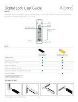
6128 /6129 Motorized lock —
housed within the safe. Provides for
Bank and Service modes of operation.
Keypad Extension Base — Installed
under the keypad. This is required
when using the lock’s Service Mode
operation or audit trail function. The
extension base provides a green LED
to indicate “Status 1”, and a red LED to
indicate “Status 2” and a yellow LED to
indicate “Mode” of lock operation. The
extension base also provides a port for
communication with Touch Keys.
Keypad — on front of safe door. This
is a 12-key alphanumeric keypad used
to enter PIN codes and programming
commands.
1.1 — Security Hierarchy
The Model 6128 ATM banking lock system operates in a Bank Mode only, Service Mode
only, or both Bank and Service Mode simultaneously.
Bank Mode Only - Bank users have local control of user PIN positions and codes, and
programming through the keypad.
Service Mode Only - Requires the “Lock Management System” for programming Touch
Memory Keys and generating one-time use Operation codes for service users. Bank User
PIN codes are disabled.
Bank and Service Mode - Bank users have local control of PIN positions and codes, and
limited keypad programming commands. The “Lock Management System” controls Bank
mode optional features and is used for programming Touch Memory Keys and generating
one-time use codes.
1.2 — About Your Locking System
The Model 6128/6129 Comptronic™ Electronic Lock has the following
hardware components:

4
630-600
MODEL 6128/6129 PROGRAMMING & OPERATIONS GUIDE
Each time you press a number, letter, or other character on the keypad, it beeps and the
keypad’s red LED flashes. If there is no beep or LED flash, check the batteries and try again (See
section 2.10 — Changing the Batteries).
The # key acts as an enter function and must be used after each code entry.
The * key is used with Programming Command Codes. It may also be used to clear the keypad
if there is an input error, by entering the * key twice.
1.3 — Factory Default Settings
The 6128/6129 is shipped from Sargent & Greenleaf with factory default settings:
• Bank Mode — enabled / no time restriction.
• Multiple User Mode — enabled
• Time Delay — zero (0) minutes
• Duress — disabled
• Audit download — enabled
• Set Date / Time — enabled
Duress Module (optional) — Housed
within the safe. this module must
be connected to the lock to use the
duress alarm feature.
IMPORTANT: The lock responds with different beep sequences to
indicate different conditions. The beeps are indicated in the examples by
the symbol x For example, five beeps are indicated by x x x x x Always
wait for each set of beeps to end before entering another number or
letter or you will interrupt the lock’s instructions.

5
630-600
MODEL 6128/6129 PROGRAMMING & OPERATIONS GUIDE
Positions 00, 02, and 10 have default PIN Codes set at the factory:
PIN Position Description PIN Position Default PIN Code
Programmer Code 00 123456
Officer Code 02 020202
User Code 10 101010
Programmer Code (PC) can only set-up the operating parameters of the lock and download
the audit trail data. The Programmer Code cannot open the safe.
Bank User Group consists of up to 16 PIN Code positions; 2 Officers and 4 Administrators
who manage the lock programs and up to 10 Users who open and close the lock.
If the lock still has the original S&G factory default settings, you can open the lock by entering
a PIN position and PIN Code, which makes up an 8-digit User code, followed by the # key.
By default the lock is set to Multiple User mode which allows opening of the lock by entering
any valid code other than the Programmer Code. (See 3.3 Setting Access Mode).
(If lock does not open and beep patterns were heard after pressing the # key, reference
section 2.3.1 “Beep Patterns” to identify condition.)
We recommend that Users change their PIN Codes immediately after the PIN positions are
assigned (Section 3.1).
2.1 — Bank User Group, PIN Positions, and User Codes
2.1.1 — Bank User Group
Bank User Group is the factory default and is always active in each lock (unless disabled
under Service Mode operation). The Bank User Group has an access hierarchy of Officers
(PIN positions 02 and 03), Administrators (PIN positions 04, 05, 06 and 07), and Users (PIN
positions 10 through 19). See Tables A&B beginning on the next page for access privileges.
Bank User Group can be configured to operate in three different User access modes.
• Multiple User mode — any valid code for the lock (other than the Programmer Code) can be
used to open it.
• Manager / Employee mode — the Officers or Administrators enable/disable the access
privilege of individual User Codes. When in this mode the officer and Administrator Codes do not
open the lock.
• Dual Control mode— two independent User Codes are needed to open the lock. Officer and
Administrator Codes can be used to open the lock in this mode.
OPERATING THE LOCK
2.

6
630-600
MODEL 6128/6129 PROGRAMMING & OPERATIONS GUIDE
2.2 — PIN Positions and Access Responsibilities
This section defines each PIN position and the respective User functions as summarized in
Tables A & B.
PIN position 00, the Programmer position, can only configure the lock and download
the audit trail. The Programmer cannot open any locks. The Programmer Code is used in
conjunction with the Lock Management System to initiate the command to set the lock into
Service Mode of operation.
Each User is assigned a 2-digit PIN (Personal Identification Number) position and a 6-digit
PIN Code. The PIN position identifies the type of User (Programmer, User, etc.) The PIN Code
allows the User to access the lock. Together these two codes form the 8-digit User Code. Each
User can change his own PIN Code but not his PIN position.
Users will always enter both their PIN position and their PIN Code, followed by the # key.
Table A: Programmer Code
Pin Position Position Description Activity
00 Programmer Code
Example: 02 020202 #
PIN POSITION PIN CODE
• Used for initialization of Service Mode
with commands 45 and 54.
• Used in conjunction with other codes for
commands 28,32,38,73,74, and 78.
• Cannot open lock.
• Cannot add/delete other PIN Codes.
• Can change its own PIN code.
• Send duress alarm (when programmed).

7
630-600
MODEL 6128/6129 PROGRAMMING & OPERATIONS GUIDE
Table B: Bank User Group
PIN Position Position Description Access
02 - 03 Officers
• Open the lock (except when
Manager/Employee Mode is enabled).
• Enable and disable Users in
Manager/Employee Mode.
• Add new Users
(requires a second valid User Code).
• Delete Users
(requires a second valid User Code).
• Start time delay (when programmed).
• Send duress alarm (when programmed).
• Can be a valid second User Code for
Dual Control and programming.
• Change their own PIN Code.
• Open the lock
• Start time delay (when programmed).
• Send duress alarm (when programmed).
• Provide second User Code for
programming.
• Change their own PIN Code.
• Open the lock
(except when Manager/Employee
Mode is enabled).
• Enable/disable Users in
Manager/Employee Mode.
• Delete Users (requires a second valid
User Code).
• Start time delay (when programmed).
• Send duress alarm (when programmed).
• Can be a valid second User Code for
Dual Control and programming.
• Change their own PIN Code.
Users
10 - 19
04 - 07
Administrators

8
630-600
MODEL 6128/6129 PROGRAMMING & OPERATIONS GUIDE
2.3 — Beep Patterns
The following table lists the beep patterns that will be heard when using the 6128/6129 lock.
(KEB = Keypad Extension Base, SM = Service Mode Use).
2.3.1 — Beep Patterns (beep
1
is the sound emitted when any single button is pressed; beep
2
is pitched lower)
2.3.2 — Additional Actions/Conditions for Bank Mode with Keypad Extension
Action/Condition Tone & Keypad LED KEB LED (if present) Duration
Each Keystroke 1 beep
1
- 1 cycle
Low Battery 2 beep
1
Red 5 cycles
Battery too low 20 beep
1
Red 1 cycle
Start Time Delay 3 quick beep
1
Red 1 cycle
Time Delay Countdown 1 beep
1
Red Every 10 sec
Time Delay Expired 10 quick beep
1
Green 1 cycle
Open Window Countdown 2 beep
1
Green Every 6 sec.
Bolt Extension 1 beep
2
+ 1 beep
1
Red 1 cycle
Code input - Lock in 10-minute penalty time 2 brap Red (+ Amber if SM) 1 cycle
Code input - Lock Disabled 2 beep
2
Red 1 cycle
Lock ID 4/5 beep
1
+ 5 beep
2
+ 6 beep
1
Green 1 cycle
Enable lock (mgr/emp mode) 4 beep
1
Green 1 cycle
Disable lock (mgr/emp mode) 2 beep
2
Red 1 cycle
Access to program modes 5 beep
1
Green 1 cycle
Program argument confirmation 3 beep
1
Green 1 cycle
Program complete 3 beep
1
Green 1 cycle
First user entry - dual control 4 beep
1
Red 1 cycle
Mode 77 - PIN used 1 beep
2
Red 1 cycle
Mode 77 - PIN empty 1 brap Red 1 cycle
Access granted 3 beep
1
Green (+ Amber if SM) 1 cycle
Wrong input/Access denied 1 brap Red (+ Amber if SM) 1 cycle
Lock Bolt Bound and Unable to Move 4 brap Red 1 cycle
Time/Date not set before Initialization Attempted 2 brap + 2 brap Red 1 cycle
Attempt to use a disabled touch key
2 beep
2
+ 1 brap
Red 1 cycle
Attempt to use a touch key not formatted for system
4 beep
2
+ 1 brap
Red 1 cycle
Action/Condition Tone & Keypad LED KEB LEDs Duration
Audit download initiated 3 beep
1
Green (+ Amber if SM) 1 cycle
Audit download complete 3 beep
1
Green (+ Amber if SM) 1 cycle
Audit download error 1 brap Red (+ Amber if SM) 1 cycle
Valid touch key read/write 3 beep
1
Green (+ Amber if SM) 1 cycle
Touch key read/write error 1 brap Red (+ Amber if SM) 1 cycle
Clock battery too low 2 brap Red/Green alternate 2 cycles

9
630-600
MODEL 6128/6129 PROGRAMMING & OPERATIONS GUIDE
2.4 — User Access Modes and Opening the Lock
Multiple User — The lock can be opened by entering any valid code other than the Programming
Code. If time delay is activated, any valid code (except the Programming Code) can be entered to
start the time delay. Then any valid code (except the Programming Code) can be entered during
the opening window to open the lock.
Manager/Employee — The Group Officers or Administrators enable/disable the access by the
User Codes. When in this mode the Group Officer and Administrator Codes do not open the lock.
To enable your lock in Manager/Employee mode
Enter: Your 2-digit Officer/Administrator PIN position
Your 6-digit Officer/Administrator PIN Code
# x x x x
Lock is enabled for use by User PIN positions.
To disable your lock in Manager/Employee mode
Enter: Your 2-digit Officer/Administrator PIN position
Your 6-digit Officer/Administrator PIN Code
# x x
Lock is disabled for use by User PIN positions.
Dual Control —Two valid codes are required to make any programming changes or to open
the lock. These may be either User or Officer/Administrator Codes. The second code must be
entered within 60 seconds after entry of the first code. If time delay is activated, only one code
is required to start the time delay, but both codes must be entered during the opening window to
open the lock.
Time Delay —The lock may be programmed with a time delay from 0 - 99 minutes with an
opening window of 1minute to 10 minutes.
If your lock does not use the time delay
Enter: Your 2-digit PIN position
Your 6-digit PIN Code
# x x x
After the beeps, turn the safe handle to the unlocked position within 6 seconds.
2.3.3 — Additional Actions/Conditions for Service Mode
Action/Condition Tone & Keypad LED KEB LEDs Duration
Lockout initiated 3 brap Red + Amber 1 cycle
Service Mode initiated Amber Duration of SM Activity
3 beep
2
+ 2 beep
1
Secure condition —
prompt user
Amber + flash
Green
1 cycle - flash
until timeout
Prompt user
for input
1 beep
1
Amber + flash
Green
1 cycle - flash until
timeout
Lock initialization
successful
1 beep
1
Green + Amber
1 cycle
Lock initialization
failed
2 brap
Red + Amber
1 cycle

10
630-600
MODEL 6128/6129 PROGRAMMING & OPERATIONS GUIDE
If your lock uses the time delay
Enter: Your 2-digit PIN position
Your 6-digit PIN Code
#
x x x
The pre-set time delay period begins after you enter your code. During the time delay period,
the lock beeps once every 10 seconds. At the end of the time delay, the lock will beep rapidly 10
times to signal the start of the opening window, the period during which you can open the lock.
During the opening window, the lock beeps twice every 6 seconds. You must now:
Enter: Your 2-digit PIN again
Your 6-digit User Code again
#
x x x
2.5.— Keypad Input Errors and Clearing the Lock
If you make a mistake while entering a User Code, press * twice at any time to clear the lock
and start over. If you hear a single long beep after entering the # key you have made an error.
Press * key twice to clear and try again, or you can wait 10 seconds and the lock will clear itself.
CAUTION: During normal entry, don’t wait more than 10 seconds between
entries or the lock will clear and you will have to start over.
2.6 — Penalty Time (Bank Mode)
If you enter 5 incorrect codes in a row, the lock goes into a 10-minute penalty time and
cannot be opened. Once in penalty time, additional input does not affect the lock or increase the
penalty time. You must wait 10 minutes before any valid code entry will be accepted. If you enter
a code (valid or invalid) during the lockout time period, the lock will emit two long beeps and will
not open.
2.7 — Lockout (Service Mode)
In the unlikely event that the lock is put into penalty time five times in a row, the lockout
function will engage. When you attempt to enter a code, the lock will emit three braps, but
will not operate. The lock will have to be reset with a red management key. Contact your lock
software administrator or dispatcher for the proper key and code.
2.8 — Bolt Extension Indicator
When the lock bolt extends to the locked position, you will hear one double-beep
(low then high pitch).

11
630-600
MODEL 6128/6129 PROGRAMMING & OPERATIONS GUIDE
2.9 — Low Battery Indicator
If you enter a correct User Code and hear 5 double-beeps when the lock opens, the batteries
are low. Change the batteries.
If the batteries are so low the lock can't work properly, the lock beeps 20 times when a User
code is entered. The lock will not open. Change the batteries right away and re-enter a User code
to open the lock.
The 9V batteries are located behind the keypad.
2.10 — Changing the Batteries
The lock will not lose any codes or program settings while you replace the batteries.
Your lock uses two 9-volt alkaline batteries. We recommend Duracell
®
alkaline batteries.
To change the batteries, carefully remove the
keypad housing by lifting the bottom edge (closest to
the S&G logo) and easing it off the base. Detach both
batteries from the terminals. Insert the new batteries,
supporting the top of each battery holder with your
other hand to prevent bending or breaking the holder.
2.11 — iButton Touch Key
The touch key allows you to transfer the audit trail from the lock to your computer. The audit
trail is a time and date stamped record of all lock activity. The touch key is also used in the
authorization of Service Mode Users at the lock.
The Sargent & Greenleaf Lock Management
System software or S&G’s Audit Manager software
must be installed on your computer before you can
upload and use the audit trail information stored in
your lock. For more instructions on downloading the
audit trail see Section 3.2.

12
630-600
MODEL 6128/6129 PROGRAMMING & OPERATIONS GUIDE
3.1 — Command 22: Changing a PIN Code
Use Command 22 to change your own PIN Code. Always change codes with the safe door
open. When changing a User Code, you will enter both the 2-digit PIN position and the 6-digit PIN
Code. The PIN position does not change.
To change a PIN Code, perform the following 4 steps
(A PIN Code can contain any numbers/letters except # or *):
Step 1. Enter: 2 2 *
Step 2. Enter: 2-digit PIN position
Current 6-digit PIN Code
#
x x x x x
Step 3. Enter: 2-digit PIN position
New 6-digit PIN Code
#
x x x
Step 4. Enter: 2-digit PIN position again
New 6-digit PIN Code again
#
x x x
Try the new PIN Code at least three times to confirm operation before closing the safe door.
PROGRAMMING THE LOCK IN BANK MODE
3.
These programming commands allow you to perform a variety of lock functions.
Command .........Description/Function
2 2 * .............Change PIN Code.
2 8 * .............Download the Audit Trail – Optional in Service Mode.
3 2 * .............Select Access Mode.
3 8 * .............Enable/Disable Duress – Duress Module required.
4 3 * .............Identify the type of lock.
4 5 * .............Multiple (Remote) Lock Initialization – Service Mode function
5 4 * .............Single Lock initialization – Service Mode function.
5 7 * .............Microprocessor Reset
7 3 * .............Set date. (Bank Mode only)
7 4 * .............Add or delete User PIN Codes & Set Time Delay.
7 7 * .............Verify PIN position.
7 8 * .............Set time. (Bank Mode only)
8 2 * .............Status Check (Lock Time and Date)

13
630-600
MODEL 6128/6129 PROGRAMMING & OPERATIONS GUIDE
3.2 — Command 28: Audit Download
The 6128/29 Lock Audit Trail can store as many as 400 time and date events. Some
examples of events are:
• Adding or deleting a User code.
• Changing a code.
• Opening or closing the lock. (Bank and Service Mode Users)
• Programming commands, such as setting the date. (Bank and Service Mode Users)
The audit trail can be downloaded to a Touch Memory key and uploaded to a computer
using the Sargent and Greenleaf Comptronic Lock Management System software. Complete
instructions are provided with the software.
To download the Audit Trail, perform the following 4 steps:
Step 1. Enter: 2 8 *
Step 2. Enter: 2-digit Programmer PIN position (00)
6-digit PIN Code followed by #
Step 3. Enter: 8 digit cipher code and # as described in the Lock Management
software instructions.
Step 4. Press the silver face of the Touch Memory Key into the corresponding
port (the round depression) on the keypad extension. The touch key will snap into
place and will be retained.
The yellow LED will remain on while the audit trail is downloading to the Touch Memory
Key. This takes about 20 seconds.
The lock beeps 3 times x x x when the download is complete.
If you hear an error beep (one long continuous beep), the audit
trail was not downloaded properly. You must start the download
over, beginning with Step 1.
After you’ve successfully downloaded the audit trail information
into the Touch Key, follow the Lock Management System
instructions provided with the Lock Management System
software to upload the data to your computer.
3.3 — Command 32: Setting the Access Mode
The lock may be set for Multiple User, Manager/Employee, or Dual Control Modes.
Multiple User — The lock can be opened by entering any valid code, except for the
Programming Code.
Manager/Employee — The Group Officers or Administrators enable/disable the access of
individual User Codes. When in this mode, the Group Officer and Administrator Codes do not
open the lock.
Dual Control — Two valid User Codes are required to make any programming changes or
to open the lock. These may be either User or Manager Codes. The second code must be
entered within 60 seconds after entry of the first code. If time delay is activated, only one
code is required to start the time delay, but both codes must be entered during the opening
window to open the lock.

14
630-600
MODEL 6128/6129 PROGRAMMING & OPERATIONS GUIDE
Enable the Manager/Employee Mode
The lock may be enabled for Manager/Employee mode by performing the following 5 steps:
Step 1. Enter: 3 2 *
Step 2. Enter: 2-digit Programmer PIN position (00)
6-digit PIN Code # x x x x x
Step 3. Enter: A valid 2-digit Officer or Administrator PIN position (02-07)
6-digit PIN Code # x x x x x
Step 4. Enter: 2 (Function Number) # x x x
Step 5. Enter: 2 (Function Number) # x x x
The lock now requires input of a Management code to enable the User codes.
Enable the Dual Control Mode
The lock may be set for Dual Control mode operation by performing the following 5 steps:
Step 1. Enter: 3 2 *
Step 2. Enter: 2-digit Programmer PIN position (00)
6-digit PIN Code # x x x x
Step 3. Enter: A valid 2-digit Officer or Administrator PIN position (02-07)
6-digit PIN Code # x x x x x
Step 4. Enter: 3 (Function Number) # x x x
Step 5. Enter: 3 (Function Number) # x x x
The lock is now set in Dual Control mode requiring two valid User or Management
codes to gain access.
Enable the Multiple User Mode
The lock may be enabled for Multiple User mode by performing the following 5 steps:
Step 1. Enter: 3 2 *
Step 2. Enter: 2-digit Programmer PIN position (00)
6-digit PIN Code # x x x x x
Step 3. Enter: A valid 2-digit Officer or Administrator PIN position (02-07)
6-digit PIN Code # x x x x x
Step 4. Enter: 4 (Function Number) # x x x
Step 5. Enter: 4 (Function Number) # x x x
3.4 — Command 38: Setting the Duress Alarm Feature
The model 6128/6129 lock has an optional duress, or silent alarm, option. The optional
duress module must be connected to the lock and your alarm system for this feature to work.

15
630-600
MODEL 6128/6129 PROGRAMMING & OPERATIONS GUIDE
Using the Duress Alarm Feature
To send a duress alarm to the alarm center, enter a User Code that is one number higher or
lower on the last digit of a User's normal PIN Code and press the # key.
For example, if the normal User Code is 123456 for PIN position 02, the User can activate
the duress alarm by entering 02123455 or 02123457, followed by #. If the User Code ends in
0, use 1 or 9 to activate the duress alarm. The lock will operate normally when a Duress code is
entered.
All User Codes can send the duress signal at any time. It can also be sent during
programming sequences.
Enable the Duress Alarm Feature
After the lock is installed with the module, the duress feature must be enabled by performing
the following 5 steps:
Step 1. Enter: 3 8 *
Step 2. Enter: 2-digit Programmer PIN position (00)
6-digit PIN Code
# x x x x x
Step 3. Enter: A valid 2-digit Officer or Administrator PIN position (02-07)
6-digit PIN Code
# x x x x x
Step 4. Enter: 1 (Function Number)
# x x x
Step 5. Enter: 1 (Function Number)
# x x x
The lock can now send a duress signal through the interface module.
Disabling the Duress Alarm Feature
The duress feature can be disabled without disconnecting the duress module, by performing
the following 5 steps:
Step 1. Enter: 3 8 *
Step 2. Enter: 2-digit Programmer PIN position (00)
6-digit PIN Code
# x x x x x
Step 3. Enter: A valid 2-digit Officer or Administrator PIN position (02-07)
6-digit PIN Code
# x x x x x
Step 4. Enter: 0 (Function Number)
# x x x
Step 5. Enter: 0 (Function Number)
# x x x

16
630-600
MODEL 6128/6129 PROGRAMMING & OPERATIONS GUIDE
3.5 — Command 43: Identifying the Type of Lock
At times, a service technician may need to know the type of lock is mounted on the safe door.
To identify the lock, perform the following 2 steps:
Step 1. Enter: 4 3 *
Step 2. Listen for the three sets of beeps. Use the table below to
determine the type of lock.
3.6 — Commands 45 and 54: Lock Initialization for Service Mode Use
Commands 45 and 54 are used to set the lock to Service Mode. Command 54 is used to set
the lock to Service Mode using a standard initialization key. Command 45 is used to set multiple locks
and/or remotely located locks to Service Mode using a multiple (remote) initialization key. The Sargent
& Greenleaf Lock Management Software System is required to create a programming touch key
that is used in conjunction with the 45* and 54* commands to program the lock for Service
Mode use. See Section 4.1 for Lock Initialization instructions.
3.7 — Command 57: Microcontroller Reset
This command is used to reset the microcontroller inside the lock without removing
power. Simply press 5 7 *. The keypad extension LEDs will all flash momentarily. No code or
programming information in the lock will be altered.
3.8 — Command 73: Set Date - Bank Mode Only
You must set the date in order to use the audit trail function. The date should be entered in
DDMMYY format, where DD = day, MM = month, and YY = year. The Date should be set prior to
initializing the lock for Service Mode use. To set the date, perform the following 5 steps:
Step 1. Enter: 7 3 *
Step 2. Enter: 2-digit Programmer PIN position (00)
6-digit PIN Code
# x x x x x
Step 3. Enter: 2-digit PIN position (02-19) for any administrator, officer, or user
6-digit Code for the PIN position just entered
# x x x x x (continued on next page)
Beep Set Number of Beeps Number of Beeps
1st set (high pitch) 4 5
2nd set (low pitch) 5 5
3rd set (high pitch) 6 6
Type of Lock 6128: Deadlocking Bolt 6129: Push/Pull Bolt

17
630-600
MODEL 6128/6129 PROGRAMMING & OPERATIONS GUIDE
Step 4. Enter: Date in DDMMYY format
#
x x x
Step 5. Enter: Confirm date by entering it again in DDMMYY format
#
x x x
Example
To set the date as July 4, 2000 (using the factory default Codes):
Step 1. Enter: 7 3 *
Step 2. Enter: 0 0
1 2 3 4 5 6 #
x x x x x
Step 3. Enter: 0 2
0 2 0 2 0 2 #
x x x x x
Step 4. Enter: 0 4 0 7 0 0 #
x x x
Step 5. Enter: 0 4 0 7 0 0 #
x x x
3.9 — Command 74: Add or Delete Code Positions
Add a New User Position
To add or delete User positions, perform the following 5 steps:
Step 1. Enter: 7 4 *
Step 2. Enter: 2-digit Officer PIN position (02 or 03)
6-digit PIN Code
#
x x x x x
Step 3. Enter: A valid 2-digit PIN position (Officer, Administrator, or User)
6-digit PIN Code
#
x x x x x
Step 4. Enter: New 2-digit PIN position
A 6-digit PIN Code
#
x x x
Step 5. Enter: New PIN position again to confirm
6-digit PIN Code again to confirm
#
x x x
After a User has been assigned a PIN position and a PIN Code, we recommend that each User
change his or her PIN Code using Command 22.

18
630-600
MODEL 6128/6129 PROGRAMMING & OPERATIONS GUIDE
Example
Add PIN position 14 (using the factory default codes). Note that for the new User you can
assign any PIN Code as long as it does not contain * or # as one of the digits.
Step 1. Enter: 7 4 *
Step 2. Enter: 0 2
0 2 0 2 0 2 #
x x x x x
Step 3. Enter: 1 0
1 0 1 0 1 0 #
x x x x x
Step 4. Enter: 1 4
1 4 1 4 1 4 #
x x x
Step 5. Enter: 1 4
1 4 1 4 1 4 #
x x x
The User should now change his PIN Code using Command 22.
Delete a User
To delete a User you only need to know his 2-digit PIN position and perform the following 5 steps.
Step 1. Enter: 7 4 *
Step 2. Enter: 2-digit Officer or Administrator PIN position.
6-digit PIN Code
#
x x x x x
Step 3. Enter: A valid 2-digit PIN position (Officer, Administrator, or User)
6-digit PIN Code
#
x x x x x
Step 4. Enter: 2-digit PIN position to be deleted
#
x x x
Step 5 Enter: 2-digit PIN position again to confirm
#
x x x
Example
Delete the User for PIN 14.
Step 1. Enter: 7 4 *
Step 2. Enter: 0 2
0 2 0 2 0 2 #
x x x x x
Step 3. Enter: 1 0
1 0 1 0 1 0 #
x x x x x (continued on next page)

19
630-600
MODEL 6128/6129 PROGRAMMING & OPERATIONS GUIDE
Step 4. Enter: 1 4 #
x x x
Step 5. Enter: 1 4 #
x x x
3.10 — Command 74: Setting Up the Time Delay
Time Delay Feature — Bank Mode only
The 6128/6129 can be programmed with a time delay feature. Time delay applies to
Bank Users only.
The time delay can be set from 0 to 99 minutes. The LED red light on the keypad flashes and
a single beep sounds every 10 seconds as a reminder that the lock is in the time delay period.
When the time delay expires, the lock emits 10 rapid beeps to indicate that it can now be
opened. During this opening window the lock beeps and the LED flashes twice every 6 seconds.
The opening window factory default is set for 2 minutes, and the opening window can be set
from 1 to 10 minutes.
To open the lock, a User must enter a his or her User Code to start the time delay period, wait
the length of the time delay period and then enter a valid User Code during the opening window.
If the lock is not opened during the open window period, it automatically resets and the process
must be repeated.
The 6128/6129 comes from the factory with no time delay set.
Set time delay duration
If the time delay has already been set, enter a User Code to start the time delay. When
the time delay expires (the lock emits 10 rapid beeps) and the opening window has begun,
immediately proceed to change the time delay by performing the following 6 steps:
Step 1. Enter: 7 4 *
Step 2. Enter: 2-digit Programmer PIN position (00)
6-digit PIN Code
#
x x x x x
Step 3. Enter: A valid 2-digit Officer or Administrator PIN position (02-07)
6-digit PIN Code
#
x x x x x (continued on next page)
NOTES:
1. If the time delay has already been set, changes to the opening window and
time delay duration can only be made during the opening window.
2. Use Command 74* to set both the time delay and the opening window.
Enter the respective function number 00 or 01, for the desired setting.
IMPORTANT: Do not set the time delay until you have finished all other
programming functions or you will have to wait through the time delay before
making any other programming changes.
/