Page is loading ...

A-Series With Display
™
ACCESS MANAGEMENT SYSTEM
Models 3006-2xx, 3007-2xx, 3028-2xx, and 3029-2xx
Programming and
Operations Guide
The Sargent & Greenleaf A-Series with Display
TM
Locks (models 3006-2xx, 3007-2xx, 3028-2xx, and 3029-2xx) are
designed to provide a high level of security combined with flexible features that allow multiple levels of control over
normal operations and service access. Follow these instructions carefully to get the best possible use from your lock.
• For instructions in English, visit the website: www.sargentandgreenleaf.com/ASeriesWithDisplay/
• Für Anweisungen auf Deutsh besuchen Sie bitte die folgende website: www.sargentandgreenleaf.com/ASeriesWithDisplay/
• Pour obtenir les instructions en français, veuillez consulter le site ci-dessous: www.sargentandgreenleaf.com/ASeriesWithDisplay/
• Para obtener instrucciones en español, visite la siguiente página web: www.sargentandgreenleaf.com/ASeriesWithDisplay/
Introducti on
• It is recommended you run the latest version of Lock Management System (LMS). Running an older version of LMS
may not give you access to all features of lock firmware.
• S&G electronic safe locks incorporate sophisticated electronic circuitry. These locks are suitable for indoor use
only.
• The keypad should only be cleaned with a soft, dry cloth. Avoid using solvents or liquids.
• Never attempt to lubricate the lock or keypad components. Service should only be performed by a qualified
technician.
• Anytime the keypad is removed from its mounting base, either disconnect the lock cable or support the keypad
so that it does not hang by the cable. This could adversely affect the cable connector or the keypad receptacle.
• Each time a button is pressed and the lock accepts the input, it will emit a beep, the red LED on the keypad will
flash momentarily, and a * will be displayed on the screen.
• All the letters of the English alphabet are displayed on the keypad. This allows you to devise numeric,
alphanumeric, or word-based codes. Use whatever approach works best for you.
• All codes end with #. This signals to the lock that you have finished entering all digits of the code.
• Personal data directly related to a code holder, such as a birthdate, should not be used in making up a lock code.
Avoid codes that can be easily guessed.
• After the lock is changed to a new code, check the lock function by locking and unlocking at least
3 times with the container door open. Make sure the lock functions correctly before closing the door.
• The audit features, peripheral devices and accessories, software features, one-time code functionality, USB
functionality, and other additional features are beyond the scope of the UL 2058 standard and are not a part of the
UL Listing.
Sargent & Greenleaf, Inc.
One Security Drive
Nicholasville, KY 40356
Phone: (800)-826-7652 Fax: (800)-634-4843
Phone: (859)-885-9411 Fax: (859)-887-2057
Sargent & Greenleaf S.A.
9, Chemin du
Cr
ose
t
1024 Ecublens, Switzerland
Phone: +41-21 694 34 00
Fax: + 41-21 694 34 09
Copyright 2005-2018 Sargent & Greenleaf, Inc.
Document 630-902
Revised 05/10/2019

Page:2
TABLE OF
C
ONTENT
S
1. GENERAL INFORMATION .............................................................................................................................................. 4
1.1 — About Your Locking System....................................................................................................................... ........... 4
1.2 — Factory Default Settings ..................................................................................................................................... 4
2. OPERATING THE LOCK .................................................................................................................................................. 5
2.1 — Operating Mode, PIN Positions, and User Codes ................................................................................................ 5
2.2 — PIN Positions and Access Responsibilities (Bank Mode) ...................................................................................... 5
2.3 — Beep Patterns .................................................................................................................................................... 6
2.4 — Opening the Lock ............................................................................................................................................... 7
2.5 — Keypad Input Errors and Clearing the Lock ....................................................................................................... 7
2.6 — Penalty Time (Bank Mode & Service Mode)...................................................................................................... 7
2.7 — Lockout (Service Mode).................................................................................................................................... 7
2.8 — Bolt Extension Indicator ........................................................................................................................... ....... 7
2.9 — Low Battery Indicator.................................................................................................................... ....................... 8
2.10 — Changing the Batteries ....................................................................................................................................... 8
2.11 — iButton Touch Key ............................................................................................................................. ................. 8
2.12 — USB Flash Drive (optional – for Audit Trail download)......................................................................................... 9
3. PROGRAMMING THE LOCK......................................................................................................................................... 10
3.1 — Command 00: Enable/Disable Manual Secure Mode......................................................................................... 10
3.2 — Command 03: Set Daylight Savings Time – Time Change .................................................................................. 10
3.3 — Command 04: Set Daylight Savings Time – Start Date....................................................................................... 11
3.4 — Command 05: Set Daylight Savings Time – End Date ......................................................................................... 11
3.5 — Command 06: Verify Daylight Savings Mode Settings....................................................................................... 12
3.6 — Command 10: Enable Daylight Savings Time................................................................................................... 12
3.7 — Command 11: Set Date .................................................................................................................................... 12
3.8 — Command 12: Set Time .................................................................................................................................... 13
3.9 — Command 13: Start the Clock ........................................................................................................................... 13
3.10 — Command 22: Changing a PIN Code............................................................................................................... 14
3.11 — Command 28: Audit Download (Bank Mode).................................................................................................. 15
3.12 — Command 32: Setting the Operating Mode .................................................................................................... 16
Enable Manager/Employee Mode .......................................................................................................................... . 16
Enable Dual Control M
o
d
e
........................................................................................................................................ 16
Enable Multiple User Mode ............................................................................................................................. ......... 16
Enable Day / Night Mode #1........................................................................................................................... .......... 17
Enable Day / Night Mode #2........................................................................................................................... .......... 17
3.13 — Command 33: Changing a PIN Code............................................................................................................... 18
3.14 — Command 38: Setting the Duress Alarm Feature ............................................................................................ 18
3.15 — Command 42: Identify Lock Type ................................................................................................................... 19

Page:3
3.16 — Command 43: Identify Lock Mechanics .......................................................................................................... 20
3.17 — Command 44: Identify Operating Mode (Bank Mode) .................................................................................... 20
3.18 — Command 45: Initializing the Lock .................................................................................................................. 20
3.19 — Command 46: Setting Up the Time Delay Override Options............................................................................ 20
3.20 — Command 47: Setting Up the Time Delay........................................................................................................ . 21
3.21 — Command 48: Setting Up the Opening Window ............................................................................................. 22
3.22 — Command 54: Initializing the Lock .................................................................................................................. 23
3.23 — Command 55: Enable/Disable the Lock (Manager / Employee Mode) ............................................................. 23
3.24 — Command 56: Enable/Disable User Disable Feature (Manager / Employee Mode)........................................... 23
3.25 — Command 57: Enable/Disable Managers and Supervisors to Open the Lock in Manager / Employee Mode .... 24
3.26 — Command 73: Set Date .................................................................................................................................. 24
3.27 — Command 75: Adding Code Positions (Manager / Employee/ Multi User / Dual)............................................... 25
3.28 — Command 76: Deleting Code Positions ............................................................................................................ . 25
3.29 — Command 77: PIN Position Verification ............................................................................................................ 26
3.30 — Command 78: Set Time .................................................................................................................................. 26
3.31 — Command 79: Identify Firmware Version ........................................................................................................ . 26
3.32 — Command 82: Verify the iButton Touch Key (Service Mode) ............................................................................. 27
3.33 — Command 83: Disabling the Time Delay Override Feature .............................................................................. 27
3.34 — Command 90: Display Lock Serial Number....................................................................................................... 28
3.35 — Command 96: Check Battery Level ................................................................................................................. 28
3.36 — Command 97: Display Time & Date ................................................................................................................. . 28
4. SERVICE MODE OPERATION ....................................................................................................................................... 28
4.1 — Service Mode Initialization (Single and Multiple) .............................................................................................. 28
4.2 — Service Mode Operation .................................................................................................................................. 29
4.3 — Service Mode Operation Codes ........................................................................................................................ 30
4.3.1 — Open Lock (Automatic Relock and Manual Secure Mode) .................................................................................. 30
4.3.2 — Program Bank Features ............................................................................................................................. ...... 31
4.3.3 — Reset User Touch Key ............................................................................................................................. ......... 31
4.3.4 — Reset Lockout ............................................................................................................................. .................... 31
4.3.5 — Revoke Dispatcher ............................................................................................................................. ............. 31
4.3.6 — Add Dispatcher ............................................................................................................................. .................. 31
4.3.7 — Un-install Lock ............................................................................................................................. ................... 31
4.3.8 — Using the Duress Alarm Feature ..................................................................................................................... . 31
4.3.9 — Download Audit Log with Manager Key ............................................................................................................ 32
4.3.10 — Set Clock Calendar (Key/No Key) ................................................................................................................... . 32
5.PIN Code Verification Worksheet (Bank Mode) ............................................................................................................ 33
APPENDIX A – Beep Patterns / Display Icons .................................................................................................................. 34
APPENDIX B – Error Codes ............................................................................................................................................. 41
APPENDIX C – 1006 / 2006 / 3006 PivotBolt Specifications ............................................................................................. 42

Page:4
1. GENERAL
I
N
F
OR
MA
TI
O
N
1.1 – About Your Locking
S
ys
te
m
The S&G A-Series with Display
TM
Electronic Lock has the following hardware components:
Lock – There are four different lock models available for the A-Series with Display
TM
Platform. These models
include the 3006 (Pivot Bolt), 3007 (Direct Drive), 3028 (Motor Driven, Dead Latching), and 3029 (Motor Driven,
Push / Pull). The lock is housed within the container.
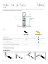
Digital Platform (DP) Keypad (31KP Series) – The 12-key alphanumeric keypad on the front of the container used to
enter PIN codes and programming commands. The keypad will contain three LEDs (red, green, yellow), a beeper
to indicate the different states of the lock, and a display module. The keypad also contains a USB connector that
will allow a flash drive to be connected.
The * key is used with Programming Command Codes. It may also be used to clear the keypad if there is an input error
by entering the * key twice.
Each time you press a number, letter, or other character on the keypad, it beeps and the keypad’s red LED flashes. If
there is no beep or flash, check the batteries and try again (See section 2.10 — Changing the B
a
tte
r
i
e
s).
The # key acts as an enter function and must be used after each code entry.
The lock responds with different beep sequences to indicate
different conditions. The beeps are indicated in the examples
by the symbol Q. For example, five beeps are indicated by
QQQQQ. You should always wait for each set of beeps to end
before entering another number or letter, or you will
interrupt the lock’s instructions.
1.2 — Factory Default
S
ett
i
n
gs
The A-Series with Display
TM
Lock is shipped from Sargent & Greenleaf with factory default settings:
• Bank Mode – enabled (Service Mode disabled)
• Multiple User Mode – enabled (Time Delay – 0 minutes; Duress – disabled)
• Positions 00, 02, and 10 have default PIN Codes set at the factory:
1. Programmer Code (00) - 00123456
2. Manager Code (02) - 02020202
3. User Code (10) - 10101010
The Programmer Code (PC) can only set up the operating parameters of the lock and download the audit trail data.
The Programmer Code cannot open the container.
The A-Series with Display
TM
Lock has the capacity for up to 30 PIN Code positions: 1 Programmer, 3 Managers, 6
Supervisors who manage the lock programs, and up to 20 Users. PIN Codes 01-29 can open the lock.
To open the lock, use the factory setting for PIN position 10 with PIN Code 10101010. Enter 10101010# and the lock
should open. (If the lock does not open and beep patterns were heard after pressing the # key, check section 2
.
3
“Beep Patterns” to identify condition.)
We recommend that Users change their PIN Codes immediately after the PIN positions are assigned (Changing a
P
I
N
Code – Section 3
.
10).

Page:5
2. OPERATING THE
L
O
C
K
2.1 —
Operating
Mode, PIN
Positions
,
and User C
od
e
s
The A-Series with Display
TM
Lock has a code hierarchy of
o Programmer (PIN position 00)
o Managers (PIN positions 01, 02, 03)
o Supervisors (PIN positions 0409)
o Users (PIN positions 10 through 29)
See Tables A & B on page 5 and 6 for access pri
v
il
e
g
e
s.
The lock can be configured to operate in five different User access modes.
o Multiple User mode — Any valid code (Supervisor, Manager, or User) can open the lock.
o Manager/Employee mode — The Managers or Supervisors enable/disable the access privilege of individual
User Codes. When in this mode, the Manager and Supervisor Codes do not open the lock.
o Dual Control mode— Two independent User Codes are needed to open the lock. Manager and Supervisor
Codes can be used to open the lock in this mode.
o Day/Night mode #1 — Two independent User Codes are needed to open the lock in “night” mode, and any
valid code (Supervisor, Manager or User) can open the lock in “day” mode.
o Day/Night mode #2 — Any valid code (Supervisor, Manager or User) can open the lock in “day” mode. The
lock cannot be opened in “night” mode.
2.2 — PIN
Positions
and Access
Responsibilities
(Bank
M
od
e
)
This section defines each PIN position and the respective User functions as summarized in Tables A & B.
PIN position 00, the Programmer position, can only configure the lock and download the audit trail. The Programmer
cannot open any locks.
Each User is assigned a 2-digit PIN (Personal Identification Number) position and an 8-digit PIN Code. The PIN position
identifies the type of User (Programmer, User, etc.) The PIN Code allows the User to access the lock. Please note that the
PIN position is not part of the code that is entered. Each User can change their own PIN Code but not PIN position. Users
will always enter their 8-digit PIN Code, followed by the # key.
Example: 0 2 0 2 0 2 0 2 #
TABLE A: Programmer
Co
de
PIN
Pos
i
t
i
on
Position
D
e
s
c
r
i
pt
i
on
A
c
t
i
v
i
t
y
00
Programmer Code
Cannot open lock.
Cannot add/delete other PIN Codes.
Can change their PIN code.
Send duress alarm (when programmed).
Can be used to program the lock functions (audit
downloads, time delay, set time and date).

Page:6
TABLE B: User G
roups
PIN
Pos
i
t
i
on
Position
D
e
s
c
r
i
pt
i
on
A
c
t
i
v
i
t
y
01 – 03
Managers
Open the lock.
Add new Users.
Delete Users.
Start time delay (when programmed).
Send duress alarm (when programmed).
Change their PIN Code.
04 – 09
Supervisors
Open the lock.
Delete Users.
Start time delay (when programmed).
Send duress alarm (when programmed).
Change their PIN Code.
10 – 29
Users
Open the lock.
Start time delay (when programmed).
Send duress alarm (when programmed).
Change their PIN Code.
2.3 — Beep
P
a
tte
r
n
s
The following table lists the beep patterns heard when using the A-Series with Display
TM
Lock.
*** beep1 is the sound emitted when any single button is pressed
*** beep2 is pitched lower than b
ee
p1
*** brap is the long error signal
TABLE C: Beep
Pa
tt
e
rns
Action/C
ond
i
t
i
on
Tone & Keypad
L
E
D
LED C
o
l
or
D
ur
at
i
on
Normal Condition
-
-
-
Each Keystroke
1 b
ee
p1
-
1 cycle
Low Battery Warning
2 b
ee
p1
Red
5 cycles
Low Battery Lockout
20 b
ee
p1
Red
1 cycle
Start Time Delay
3 quick b
ee
p1
Red
1 cycle
Time Delay Countdown
1 b
ee
p1
Red
Every 10 seconds
Time Delay Expired
10 quick b
ee
p1
Green
1 cycle
Opening Window Countdown
2 b
ee
p1
Green
Every 10 seconds
Bolt Extension
1 beep2 + 1 b
ee
p1
Red
1 cycle
Code Input – Lock in Penalty Time
2 br
a
p
Red
1 cycle
Code Input – Lock Disabled
2 b
ee
p2
Red
1 cycle
Enable Lock (Mgr/Emp Mode)
4 b
ee
p1
Green
1 cycle
Disable Lock (Mgr/Emp Mode)
2 b
ee
p2
Red
1 cycle
Access to Program Modes
5 b
ee
p1
Green
1 cycle
Program Argument Confirmation
3 b
ee
p1
Green
1 cycle
Program Complete
3 b
ee
p1
Green
1 cycle
Mode 77 – PIN Used
1 b
ee
p2
Red
1 cycle
Mode 77 – PIN Empty
1 brap
Red
1 cycle
Wrong Input/Access Denied
1 br
a
p
Red
1 cycle
CAUTION: During normal entry, don’t wait more than 10 seconds between entries, or the lock will clear and you will have to start over.

Page:7
2.4 —
Opening
the
Lock
Time Delay —The lock may be programmed with a time delay from 0 - 99 minutes with an opening window of 1 minute
to 99 minutes.
If your lock does not use the time d
e
l
a
y
:
Enter: Your 8-digit PIN Code #
Turn the safe handle to the unlocked position within 6 seconds.
If your lock uses the time d
e
l
a
y
:
Enter: Your 8-digit PIN Code # ♪♪♪
(signals start of time
d
e
l
a
y
)
The pre-set time delay period begins after you enter your code. During the time delay period, the lock beeps once every 10
seconds. At the end of the time delay, the lock will beep rapidly 10 times to signal the start of the opening window, the
period during which you can open the lock.
During the opening window, the lock beeps twice every 10 seconds. You must now:
Enter: Your 8-digit PIN Code again #
Turn the safe handle to the unlocked position within 6 seconds.
2.5 — Keypad Input Errors and
Clearing
the
Lock
If you make a mistake while entering a User Code, press * twice at any time to clear the lock and start over. If you hear a
brap after entering the # key, you have made an error.
Press * key twice to clear and try again, or you can wait 10 seconds and the lock will clear itself.
2.6 — Penalty Time (Bank Mode & Service
M
od
e
)
If you enter 5 incorrect codes in a row, the lock goes into a 10-minute penalty time and cannot be opened. Once in penalty
time, additional input does not affect the lock, and you must wait 10 minutes before any valid code entry will be accepted.
2.7 — Lockout (Service
M
od
e
)
In the unlikely event that the lock is put into penalty time five times in a row, the lockout function will engage. When you
attempt to enter a code, the lock will emit three braps but will not operate. The lock will have to be reset with a red
management key. Contact your lock software administrator or dispatcher for the proper key and code.
2.8 — Bolt
Extension
In
d
i
c
a
t
o
r
When the lock bolt extends to the locked position, you will hear one double beep (low pitch, then high pitch) and the red
LED will flash.

Page:8
2.9 — Low Battery
In
d
i
c
a
t
o
r
If you enter a correct User Code and hear 5 double beeps when the lock opens, the batteries are low. Change the
batteries. You will also see the following icon on the screen:
If the batteries are so low that the lock can’t open, the lock will beep 20 times when a User code is entered. Change
the batteries right away and re-enter a User code to open the lock.
Please note that the 9V batteries are located inside the keypad.
2.10 —
Changing
the
B
a
tte
r
i
e
s
The lock will not lose any codes or program settings while you replace the batteries. Yo u r lock uses two 9-volt alkaline
batteries. We recommend Duracell® alkaline batteries.
To change the batteries, carefully pull the keypad housing away from the door. Move the spring clips under each battery
to release the battery. Insert the new batteries into the compartment and move the spring clips back into place. Please
note that the polarity of the battery is designated on the inside of the compartment. Press the keypad housing firmly back
onto the base.
2.11 — iButton Touch
Ke
y
The iButton touch key allows you to transfer the audit trail from the lock to your computer. The audit trail is a time and
date stamped record of all lock activity. The touch key is also used in the authorization of Service Mode Users at the lock.
The S&G Lock Management System or Audit Manager software must be installed on your computer before you can
upload and use the audit trail information stored in your lock.
2.12 — USB Flash Drive
(optional
– for Audit Trail
do
w
n
l
o
a
d
)
A connector for a USB flash drive is provided on the front of the keypad. This connection allows a flash drive to be
inserted into the key so that the audit trail can be downloaded.

Page:9
3.
PROGRAMMING
THE
L
O
C
K
These programming commands allow you to perform a variety of lock functions.
Command . . . . . . . . . . . . . Description/Function
0 0 *. . . . . . . . . . . . . Enable/disable manual secure
0 3*. . . . . . . . . . . . . Set Daylight Savings Time – time change
0 4 *. . . . . . . . . . . . . Set Daylight Savings Time – start date
0 5 *. . . . . . . . . . . . . Set Daylight Savings Time – end date
0 6 *. . . . . . . . . . . . . Verify Daylight Savings Time – enabled/disabled
1 0 *. . . . . . . . . . . . . Enable Daylight Savings Time
1 1 *. . . . . . . . . . . . . Set date
1 2 *. . . . . . . . . . . . . Set time
1 3 *. . . . . . . . . . . . . Start clock
2 2 *. . . . . . . . . . . . . Change PIN code (same function as 3 3
*)
2 8 *. . . . . . . . . . . . . Download the audit trail
3 2 *. . . . . . . . . . . . . Set the mode of operation
3 3 *. . . . . . . . . . . . . Change PIN code (same function as 2 2
*)
3 8 *. . . . . . . . . . . . . Enable/disable duress
4 2 *. . . . . . . . . . . . . Identify the type of lock
4 3 *. . . . . . . . . . . . . Identify the lock mechanics
4 4 *. . . . . . . . . . . . . Identify the operating mode
4 5 *. . . . . . . . . . . . . Initialize the lock (into service mode)
4 6 *. . . . . . . . . . . . . Setup time delay override (TDO) type
4 7 *. . . . . . . . . . . . . Setup time delay value
4 8 *. . . . . . . . . . . . . Setup opening window value
5 4 *. . . . . . . . . . . . . Initialize the lock (into service mode)
5 5 *. . . . . . . . . . . . . Enable/disable lock (manager/employee mode)
5 6 *. . . . . . . . . . . . . Manager/employee mode type
5 7 *. . . . . . . . . . . . . Manager/employee mode – opening settings
5 8 *. . . . . . . . . . . . . Enable/disable day/night mode
5 9 *. . . . . . . . . . . . . Set opening window for day/night mode
7 3 *. . . . . . . . . . . . . Set date
7 5 *. . . . . . . . . . . . . Adding a code
7 6 *. . . . . . . . . . . . . Deleting a code
7 7 *. . . . . . . . . . . . . Verify PIN positions
7 8 *. . . . . . . . . . . . . Set date
7 9 *. . . . . . . . . . . . . Identify the firmware version
8 2 *. . . . . . . . . . . . . Verify the iButton touch key
8 3 *. . . . . . . . . . . . . Disable time delay override (TDO)
9 0 *. . . . . . . . . . . . . Display lock serial number
9 6 *. . . . . . . . . . . . . Check battery level
9 7 *. . . . . . . . . . . . . Display current time & date

Page:10
3.1 —
Command
00: Enable/Disable Manual Secure Mode
You can enable or disable the motor behavior in the 3006/3028/3029 locks. This will keep the lock motor in the retracted
or unlocked position until you enter the 00# command, causing the lock motor/bolt to return to the secure position. This
should be performed before initialization. To enable/disable manual secure mode, perform the following steps:
Step 1 Enter: 0 0 *
Step 2 Enter: 8-digit Programmer PIN Code (00)# ♪♪♪♪♪
Step 3
Enter: 1 - ON or 0 - OFF# ♪♪♪
Step 4
Enter: 1 - ON or 0 - OFF# ♪♪♪
Manual Secure
Enter Code
********
Manual Secure
1-ON 0-OFF
Confirm
1-ON 0-OFF
3.2 —
Command
03: Set Daylight Savings Time – Time C
h
a
n
g
e
When implementing Daylight Savings Time (DST) features, you must setup the hour of the day when the DST
changes will be made. This is the time when the clock inside the lock will increment 1 hour or decrement 1 hour,
depending on the dates when DST is enabled. To setup the DST time change, perform the following steps:
Step 1 Enter: 0 3 *
Step 2 Enter: 8-digit Programmer PIN Code (00)# ♪♪♪♪♪
Step 3 Enter: Time in HH format (always 2 digits)# ♪♪♪
Step 4 Enter: Time in HH format (always 2 digits)# ♪♪♪
DST Change Time
Enter Code
********
Enter Time
HH
Confirm
Time
HH
E
x
a
mp
l
e
To set the DST change time to 2 AM (using the factory default Codes):
Step 1 Enter: 0 3 *
Step 2 Enter: 0 0 1 2 3 4 5 6 #♪♪♪♪♪
Step 3 Enter: 0 2 # ♪♪♪
Step 4 Enter: 0 2 # ♪♪♪
DST Change Time
Enter Code
********
Enter Time
02
Confirm
Time
02
3.3 — Command 04: Set
Daylight
Savings Time – Start
D
a
y
When implementing Daylight Savings Time (DST), you must set the Week, Day, and Month in which DST is set to
begin. This is the date when the lock will increment 1 hour. The range for the Week setting is 1-5. The range for the
Day setting is 1-7 (Sunday – Saturday). The range for the Month setting is 1-12 (January – December). To set the start
date, perform the following steps:
Step 1 Enter: 0 4 *
Step 2 Enter: 8-digit Programmer # ♪♪♪♪♪
Step 3 Enter: Week/Day/Month # ♪♪♪
Step 4 Enter: Week/Day/Month #
♪♪♪
DST Start Day
Enter Code
********
Enter Day
WK/DD/MM
**/**/**
Confirm
Day
WK/DD/MM
**/**/**

Page:11
E
x
a
mp
l
e
To set the start day to the last Sunday in March:
Step 1 Enter: 0 4 *
Step 2 Enter: 0 0 1 2 3 4 5 6 # ♪♪♪♪♪
Step 3 Enter: 0 4 0 1 0 3 # ♪♪♪
Step 4 Enter: 0 4 0 1 0 3 #
♪♪♪
DST Start Day
Enter Code
********
Enter Day
WK/DD/MM
**/**/**
Confirm
Day
WK/DD/MM
**/**/**
3.4 — Command 05: Set
Daylight
Savings Time – End Day
When implementing Daylight Savings Time (DST), you must set the Week, Day, and Month in which DST is set to end.
This is the date when the lock will decrement 1 hour. The range for the Week setting is 1-5. The range for the Day
setting is 1-7 (Sunday – Saturday). The range for the Month setting is 1-12 (January – December). To set the end date,
perform the following steps:
Step 1 Enter: 0 5 *
Step 2 Enter: 8-digit Programmer # ♪♪♪♪♪
Step 3 Enter: Week/Day/Month # ♪♪♪
Step 4 Enter: Week/Day/Month #
♪♪♪
DST End Day
Enter Code
********
Enter Day
WK/DD/MM
**/**/**
Confirm
Day
WK/DD/MM
**/**/**
E
x
a
mp
l
e
To set the end day to the First Sunday in November:
Step 1 Enter: 0 5 *
Step 2 Enter: 0 0 1 2 3 4 5 6 # ♪♪♪♪♪
Step 3 Enter: 0 1 0 1 1 1 # ♪♪♪
Step 4 Enter: 0 1 0 1 1 1
♪♪♪
DST End Day
Enter Code
********
Enter Day
WK/DD/MM
01/01/11
Confirm
Day
WK/DD/MM
01/01/11
3.5 — Command 06: Verify
Daylight
Savings Mode Settings
To verify the lock has disabled or enabled DST setting, perform the following:
Step 1 Enter: 0 6 *
DST Disabled
S:WK/DD/MM
E:WK/DD/MM - HH

Page:12
3.6 — Command 10: Enable
Daylight
Savings
T
i
m
e
In order to implement Daylight Savings Time (DST) features, you must enable the DST feature. Once the DST
features have been enabled, the lock will automatically update the time to match the settings that were entered with
the 03 – 05 commands. All DST options must be setup before the DST feature can be enabled. DST can be configured
before the initialization process or after bank mode has been enabled. LMS will use Standard Time for code generation.
To enable the DST features, perform the following steps:
Step 1 Enter: 1 0 *
Step 2 Enter: 8-digit Programmer PIN Code (00)#
♪♪♪♪♪
Step 3
Enter: 1 # (to enable) or 0 # (to disable) ♪♪♪
Step 4
Enter: 1 # (to enable) or 0 # (to disable) ♪♪♪
DST ON / Off
Enter Code
********
ENABLE DST
1-ON 0-OFF
CONFIRM DST
1-ON 0-OFF
E
x
a
mp
l
e
To enable the DST features (using the factory default Codes):
Step 1 Enter: 1 0 *
Step 2 Enter: 0 0 1 2 3 4 5 6 # ♪♪♪♪♪
Step 3 Enter: 1 # ♪♪♪
Step 4 Enter: 1 # ♪♪♪
DST ON / Off
Enter Code
********
ENABLE DST
1-ON 0-OFF
1
CONFIRM DST
1-ON 0-OFF
1
3.7 —
Command
11: Set
D
a
te
You must set the date to use Service Mode or audit trail functions. The date should be entered in DDMMYY format, where
DD = day, MM = month, and YY = year. The Date should be set before initializing the lock. To set the date, perform
the following steps:
Step 1 Enter: 1 1 *
Step 2 Enter: 8-digit Programmer PIN Code (00)# ♪♪♪♪♪
Step 3
Enter: Date in DDMMYY format # ♪♪♪
Step 4 Enter: Date in DDMMYY format # ♪♪♪
E
x
a
mp
l
e
Set Date
Enter Code
********
Enter Date
DD/MM/YY
**/**/**
Confirm
Date
DD/MM/YY
**/**/**
To set the date as May 25, 2017 (using the factory default Codes):
Step 1 Enter: 1 1 *
Step 2 Enter: 0 0 1 2 3 4 5 6 # ♪♪♪♪♪
Step 3 Enter: 2 5 0 5 1 7 # ♪♪♪
St
ep
4
En
ter:
2
5
0
5 1
7
#
♪♪♪
Set Date
Enter Code
********
Enter Date
DD/MM/YY
25/05/17
Confirm
Date
DD/MM/YY
25/05/17
The time & date must be set and the clock started (13*)
before the settings are saved by the lock.

Page:13
3.8 — Command 12: Set
T
i
m
e
You must set the time to use Service Mode and audit trail functions. The time should be set in HHmm format based
on a 24-hour clock, where HH = hours and mm = minutes. The time should be set before initializing the lock. The
time is to always be set in local standard time. Local standard time must be set, even though Daylight Savings Time
may be in effect. To set the time, perform the following steps:
Step 1 Enter: 1 2 *
Step 2 Enter: 8-digit Programmer PIN Code (00) # ♪♪♪♪♪
Step 3 Enter: Time in HHmm format # ♪♪♪
Step 4 Enter: Time in HHmm format # ♪♪♪
Set Time
Enter Code
********
Enter Time
HH:MM
**:**
Confirm
Time
HH:MM
**:**
E
x
a
mp
l
e
To set the time as 1:42 PM, use 13:42 (using the factory default Codes):
Step 1 Enter: 1 2 *
Step 2 Enter: 0 0 1 2 3 4 5 6 # ♪♪♪♪♪
Step 3 Enter: 1 3 4 2 # ♪♪♪
Step 4 Enter: 1 3 4 2 # ♪♪♪
Set Time
Enter Code
********
Enter Time
HH:MM
13:42
Confirm
Time
HH:MM
13:42
The time & date must be set and the clock started (13*)
before the settings are saved by the lock.
3.9 — Command 13: Start the C
l
o
c
k
After setting the time and date values, you must use a separate command to start the clock. This step helps to match the
time in the lock to your current time. To start the clock, perform the following steps (after programming time & date):
Step 1 Enter: 1 3 *
Step 2 Enter: 8-digit Programmer PIN Code (00) # ♪♪♪♪♪
Step 3
Enter: sequence to start the clock 1# ♪♪♪
Step 4
Enter: sequence to start the clock 1# ♪♪♪
Start Clock
Enter Code
********
Enter 1
To Start Clock
Enter 1
to
Confirm

Page:14
3.10 — Command 22:
Changing
a PIN C
od
e
Use command 22 to change your PIN Code. You should always leave the safe door open while changing codes. When
changing any code, you will need to enter the new 8-digit PIN Code twice for confirmation. The PIN position does not
change. Please note that command 33 performs the same functi
o
n.
To change a PIN Code, perform the following steps (A PIN Code can contain any numbers/letters except # or *):
Step 1 Enter: 2 2 *
Step 2 Enter: 8-digit PIN Code # ♪♪♪♪♪
Step 3 Enter: New 8-digit PIN Code # ♪♪♪
Step 4 Enter: New 8-digit PIN Code again #
♪♪♪
Change
Code
Enter Code
********
Enter
New
Code
********
Confirm
New
Code
********
E
x
a
mp
l
e
To change the default PIN code of 0 2 0 2 0 2 0 2 to 2 1 2 1 2 1 2 1
Step 1 Enter: 2 2 *
Step 2 0 2 0 2 0 2 0 2 # ♪♪♪♪♪
Step 3 2 1 2 1 2 1 2 1 # ♪♪♪
Step 4 2 1 2 1 2 1 2 1 #
♪♪♪
Change Code
Enter Code
********
Enter
New Code
********
Confirm
New Code
********
E
x
a
mp
l
e
To change the default PIN code of 1 0 1 0 1 0 1 0 to 2 0 1 5 2 0 1 5
Step 1 Enter: 2 2 *
Step 2 1 0 1 0 1 0 1 0 # ♪♪♪♪♪
Step 3 2 0 1 5 2 0 1 5 # ♪♪♪
Step 4 2 0 1 5 2 0 1 5 # ♪♪♪
Change Code
Enter Code
********
Enter
New Code
********
Confirm
New Code
********
Try the new PIN Code at least three times to confirm
operation before closing the safe door.

Page:15
3.11 — Command 28: Audit
Dow
nloa
d
The
A-Series
with Display
TM
Lock Audit Trail can store as many as 1,000 events that include times & dates. Some
examples of events are:
• Adding or deleting a PIN code.
• Changing a PIN code.
• Opening or closing the lock (bank mode & service mode).
• Programming commands, such as setting the date.
The audit trail can be downloaded to an approved USB flash drive using command 28 and then uploaded to a
computer using the S&G Audit Lock Audit Trail Software or the LMS Software. Complete instructions are provided
with the software.
To download the Audit Trail, perform the following steps:
Step 1 Enter: 2 8 *
Step 2 Enter: 8-digit Programmer or Manager PIN Code (00, 01, 02, 03) #
Step 3 Enter: The option for number of audit events to download (1 – 6)#
Step 4 Enter: The option for number of audit events to download (1 – 6)#
Step 5 Insert the USB flash drive into the corresponding port on the front of the keypad.
Step 6 The lock beeps 3 times (♪♪♪) when the download is complete.
Audit Download
Enter Code
********
# Events
(1-6)
*
Confirm
(1-6)
*
The yellow LED on the keypad will remain on while the audit trail is being downloaded to the USB flash drive.
Depending on the size of the Audit Trail, this could take up to 45 s
e
c
o
nds.
If you hear a BRAP (one long continuous beep), the audit trail was not downloaded properly. You must start the
download over, beginning with Step 1. After you’ve successfully downloaded the audit trail, it is stored in the Touch Key.
The available options for the number of events to download are as follows:
1 – upload the first most recent event in the audit trail
2 – upload the 8 most recent events in the audit trail
3 – upload the 32 most recent events in the audit trail
4 – upload the 64 most recent events in the audit trail
5 – upload the 128 most recent events in the audit trail
6 – upload all of the events in the audit trail (up to 1,000 events)
E
x
a
mp
l
e
Step 1 Enter: 2 8 *
Step 2 Enter: 0 0 1 2 3 4 5 6#
Step 3 6 #
Step 4 6 #
Step 5 Insert the USB flash drive into the corresponding port on the front of the keypad.
Step 6 The lock beeps 3 times (♪♪♪) when the download is complete.
Audit Download
Enter Code
********
# Events
(1-6)
6
Confirm
(1-6)
6
Follow the instructions provided with the S&G Audit Trail Software to upload the data to your computer. A
flash drive should be provided with the Audit Trail Software kit.

Page:16
3.12 — Command 32: Setting the
Operating
M
od
e
Enable
Manager/Employee
M
od
e
The lock may be enabled for Manager/Employee mode by performing the following steps:
Step 1 Enter: 3 2 *
Step 2 Enter: 8-digit Programmer Code # ♪♪♪♪♪
Step 3 Enter: 2 (Function Number) #
♪♪♪
Step 4 Enter: 2 (Function Number) # ♪♪♪
Set Lock Mode
Enter Code
********
Enter New
Mode #
2
Confi
r
m New
Mode #
2
The lock now requires input of a Management PIN code to enable the User PIN codes.
Enable Dual Control
M
od
e
The lock may be set for Dual Control mode operation by performing the following steps:
Step 1 Enter: 3 2 *
Step 2 Enter: 8-digit Programmer Code # ♪♪♪♪♪
Step 3 Enter: 3 (Function Number)#
♪♪♪
Step 4 Enter: 3 (Function Number)#
♪♪♪
Set Lock Mode
Enter Code
********
Enter New
Mode #
3
Conf
ir
m New
Mode #
3
The lock is now set in Dual Control mode requiring two valid opening PIN codes to gain access.
Once the lock has been put into dual control, it will
require a manager code and any other valid code to
change operating modes.
Enable Multiple User
M
od
e
The lock may be enabled for Multiple User mode by performing the following steps:
Step 1 Enter: 3 2 *
Step 2 Enter: 8-digit Programmer Code# ♪♪♪♪♪
Step 3 Enter: 4 (Function Number)# ♪♪♪
Step 4 Enter: 4 (Function Number)#♪♪♪
Set Lock Mode
Enter Code
********
Enter New
Mode #
4
Confi
r
m New
Mode #
4
The lock is set to Multiple User mode and can be opened using any valid opening PIN code.

Page:17
Enable Day / Night Mode
#
1
For “Day / Night Mode #1”, the customer can setup the lock so that there is an opening window where the lock can be
opened using one valid user. The opening window is established using command 59.
Once in the opening window, the lock can be enabled for “day mode” use with command 58. When the lock
is enabled for “day mode” use, a single code can be used to open the lock. The initial opening will have a 5-minute time
delay countdown before the lock can be opened in “day mode”.
At any point during “day mode”, the user can manually switch the lock back to “night mode” using command 58,
regardless of the current time or the opening window settings.
Outside of the opening window, the lock will be in “night mode”. When the lock is in “night mode”, the lock will always
require two valid PIN codes to open the lock.
The lock may be set for Day / Night Mode #1 by performing the following steps:
Step 1 Enter: 3 2 *
Step 2 Enter: 8-digit Programmer Code # ♪♪♪♪♪
Step 3 Enter: 5 (Function Number) # ♪♪♪
Step 4 Enter: 5 (Function Number) #
♪♪♪
Set Lock Mode
Enter Code
********
Enter New
Mode #
5
Confirm
New
Mode #
5
The lock is now set in “Day / Night Mode #1”. This setting requires two valid opening PIN codes to open the lock in “night”
mode and one valid opening PIN code to open the lock in “day” mode (and enabled).
Enable Day / Night Mode
#
2
For “Day / Night Mode #2”, the customer can setup the lock so that there is an opening window and the lock can only be
opened during this opening window period. The opening window is established using command 59.
The user will setup the time when “day mode” begins and ends. Any valid code can be used to open the lock in “day
mode” (i.e., during the opening window). Any opening attempt during “night mode” (i.e., outside the opening window)
will result in 2 low beeps, and the lock will not open.
The lock may be set for Day / Night Mode #2 by performing the following steps:
Step 1 Enter: 3 2 *
Step 2 Enter: 8-digit Programmer Code # ♪♪♪♪♪
Step 3 Enter: 6 (Function Number) # ♪♪♪
Step 4 Enter: 6 (Function Number) #
♪♪♪
Set Lock Mode
Enter Code
********
Enter New
Mode #
5
Confirm
New
Mode #
5
The lock is now set in “Day / Night Mode #2,” meaning that the lock can only be opened during “day” mode.

Page:18
3.13 — Command 33:
Changing
a PIN C
od
e
Use command 33 to change your PIN Code. You should always leave the safe door open while changing codes. When
changing any code, you will need to enter the new 8-digit PIN Code twice for confirmation. The PIN position does not
change. Please note that command 22 performs the same functi
o
n.
To change a PIN Code, perform the following steps (A PIN Code can contain any numbers/letters except # or *):
Step 1 Enter: 3 3 *
Step 2 Enter: 8-digit PIN Code # ♪♪♪♪♪
Step 3 Enter: New 8-digit PIN Code # ♪♪♪
Step 4 Enter: New 8-digit PIN Code again #
♪♪♪
E
x
a
mp
l
e
Change Code
Enter Code
********
Step 1 Enter: 3 3 *
Step 2 0 2 0 2 0 2 0 2 # ♪♪♪♪♪
Step 3 2 1 2 1 2 1 2 1 # ♪♪♪
Step 4 2 1 2 1 2 1 2 1 #
♪♪♪
Enter
New Code
********
Confirm
New Code
********
Change Code
Enter Code
********
Enter
New Code
********
Confirm
New Code
********
With the above example, the default PIN code of 0 2 0 2 0 2 0 2 has been changed to 2 1 2 1 2 1 2 1.
E
x
a
mp
l
e
Step 1 Enter: 3 3 *
Step 2 1 0 1 0 1 0 1 0 # ♪♪♪♪♪
Step 3 2 0 1 5 2 0 1 5 # ♪♪♪
Step 4 2 0 1 5 2 0 1 5 #
♪♪♪
Change Code
Enter Code
********
Enter
New Code
********
Confirm
New Code
********
With the above example, the default PIN code of 1 0 1 0 1 0 1 0 has been changed to 2 0 1 5 2 0 1 5.
Try the new PIN Code at least three times to confirm
operation before closing the safe door.
3.14 — Command 38: Setting the Duress Alarm
F
e
a
tu
r
e
The
A-Series
with Display
TM
Lock has an optional duress, or silent alarm, option that can be configured.
Using the Duress Alarm Fe
a
t
u
r
e
To send a duress alarm to the alarm center, enter any code that is one number higher or lower than the last number
of a normal PIN Code and press the # key.

Page:19
For example, if the normal User Code is 94507853, the User can activate the duress alarm by entering 94507852 or
94507854, followed by #. If the User Code ends in 0, use 1 or 9 to activate the duress alarm. The lock will operate
normally when a duress code is entered.
All codes can send the duress signal at any time. It can also be sent during programming sequences.
Enable Duress Alarm Fe
a
t
ure
After the lock is installed with the Duress Alarm Module, the duress feature must be enabled by performing the
following steps:
Step 1 Enter: 3 8 *
Step 2 Enter: 8-digit Programmer PIN code (00) #
♪♪♪♪♪
Step 3
Enter: 1, 2, or 3 #♪♪♪
Step 4 Enter: 2 or 3 # ♪♪♪
(OPTION 1 – disable, OPTION 2 – enable with module, OPTION 3 – enable with digital
ou
t
pu
t
)
Dures
s
Mode
Enter Code
********
Enter New
Mode Number
2
Confirm
New
Mode Number
2
The lock can now send a duress signal through the interface module.
Disabling the Duress Alarm Fe
a
t
u
r
e
The duress feature can be disabled without disconnecting the Duress Alarm Module by performing the following steps:
Step 1 Enter: 3 8 *
Step 2 Enter: 8-digit Programmer PIN code (00) #
♪♪♪♪♪
Step 3 Enter: 0
#
♪♪♪
Step 4 Enter: 0 # ♪♪♪
(OPTION 1 – disable, OPTION 2 – enable with module, OPTION 3 – enable with digital
ou
t
pu
t
)
Dures
s
Mode
Enter Code
********
Enter New
Mode Number
0
Confirm
New
Mode Number
0
3.15 — Command 42: Identify Lock
T
y
pe
Use command 42 to verify the lock type that has been setup for the lock.
Step 1 Enter: 4 2 *
Step 2 Listen for the beeps to determine the lock type.
Lock Type
A-Series
The lock will emit one low beep, one high beep, and one low beep to begin the sequence. The next set of beeps will
indicate the type of lock being used. The lock type will also be shown on the display.

Page:20
3.16 — Command 43: Identify Lock
M
e
c
h
a
n
i
cs
Use command 43 to verify the firmware version loaded into the lock.
Step 1 Enter: 4 3 *
Step 2 Listen for the beeps to determine the lock mechanics.
The lock will emit one low beep, one high beep, and one low beep to begin the sequence. The next set of beeps
will indicate the type of lock mechanics being used. The lock mechanics will also be shown on the display.
1 beep = PIVOT BOLT
2 beeps = DIRECT DRIVE
3
beeps = MOTOR DRIVE
4 beeps = MOTOR GEAR
Lock Type
Pivot Bolt
Lock Type
Motor Drive
Lock Type
Direct Drive
Lock Type
Motor Gear
3.17 — Command 44: Identify
Operating
Mode (Bank
M
od
e
)
Use command 44 to verify the firmware version loaded into the lock.
Step 1 Enter: 4 4 *
Step 2 Listen for the beeps to determine the operating mode.
The lock will emit one low beep, one high beep, and one low beep to begin the sequence. The next set of beeps
will indicate the operating mode.
2 beeps = Manager/employee mode
3 beeps = Dual control mode
4 beeps = Multiple user mode
3.18 — Command 45:
Initializing
the
Lock
Multiple
User Mode
Dual
User Mode
Manager/Employee
User Mode
The lock can be initialized into Service Mode using command 45 and a properly programmed management touch key.
Please see Section 4.1 – Initializing the Lock for more information on initializing the lock.
3.19 — Command 46: Setting Up the Time Delay
Override
O
pt
i
o
n
s
When the time delay feature is enabled, the A-Series with Display
TM
Lock can be programmed with a time delay override
(TDO) feature that will allow a specific user to bypass the time delay countdown. The time delay override code must
always be setup in PIN position 29.
There are two types of TDO available. TDO TYPE 1 requires that the time delay override code is entered within the first
minute of the time delay countdown. In other words, a User must start the time delay countdown by entering their
code. If the time delay override code is entered within the first minute, then the lock will open.
TDO TYPE 2 will allow the lock to be opened by the time delay override code without requiring another User start the
time delay countdown.
/