Page is loading ...

Form 169365 Issue – May 2008
FOREWORD
This manual contains safety information, set-up instructions, operating instructions, and maintenance procedures,
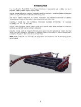
for the Model MT8 Header Transporter. Your new MT8 Header Transporter allows you to transport MD draper
headers (combine or windrower) with the M Series Windrower, truck, or combine (three-axle only). The
Transporter can be towed at highway speeds.
CAREFULLY READ ALL THE MATERIAL PROVIDED BEFORE ATTEMPTING TO UNLOAD, ASSEMBLE, OR
USE THE MACHINE.
Use this manual as your first source of information about the Transporter. If you follow the instructions given in
this manual, your Transporter will work well for many years. Use this manual in conjunction with your M Series
Self-Propelled Windrower and D Series Draper Header manuals.
Use the Table of Contents to guide you to specific areas. Review the Table of Contents to familiarize yourself
with how the material is organized.
Keep this manual handy for frequent reference and to pass on to new operators or owners. Call your dealer if you
need assistance, information, or additional copies of this manual.
RECORD THE SERIAL NUMBER OF THE TRANSPORTER IN THE SPACE BELOW.
_______________________________
Serial Number plate is located on the right side of the main beam near the front of the Transporter.


Form 169365 Issue – May 2008
TABLE OF CONTENTS
SECTION G ................................................GENERAL INFORMATION
SECTION UA ................................................. SETUP INSTRUCTIONS
SECTION OM .................................................OPERATOR’S MANUAL


SECTION G – GENERAL INFORMATION
Form 169365 Issue – May 2008
SECTION G – GENERAL INFORMATION
Section Contents
ITEM DESCRIPTION PAGE G-
1
SAFETY .........................................................................................................................................................1
1.1 SAFETY ALERT SYMBOL ......................................................................................................................1
1.2 SIGNAL WORDS .....................................................................................................................................1
1.3 SAFETY INSTRUCTIONS .......................................................................................................................2
2 RECOMMENDED TORQUES.......................................................................................................................5
2.1 GENERAL ................................................................................................................................................5
2.2 SAE BOLTS .............................................................................................................................................5
2.3 METRIC BOLTS.......................................................................................................................................5
3 ENGLISH/METRIC EQUIVALENTS..............................................................................................................6


SECTION G – GENERAL INFORMATION
Form 169365 G-1 Issue– May 2008
1 SAFETY
1.1 SAFETY ALERT SYMBOL
This safety alert symbol indicates important
safety messages in this manual and on safety
signs on the machine.
This symbol means:
ATTENTION!
BECOME ALERT!
YOUR SAFETY IS INVOLVED!
Carefully read and follow the safety message
accompanying this symbol.
WHY IS SAFETY IMPORTANT TO YOU?
ACCIDENTS DISABLE AND KILL
ACCIDENTS COST
ACCIDENTS CAN BE AVOIDED
1.2 SIGNAL WORDS
Note the use of the signal words DANGER,
WARNING, and CAUTION with safety
messages. The appropriate signal word for each
message has been selected using the following
guidelines:
DANGER
Indicates an imminently hazardous
situation that, if not avoided, will result in
death or serious injury.
WARNING
Indicates a potentially hazardous situation
that, if not avoided, could result in death or
serious injury. It is also used to alert
against unsafe practices.
CAUTION
Indicates a potentially hazardous situation
that, if not avoided, may result in minor or
moderate injury. It is also used as a
reminder of good safety practices.
1.3 SAFETY SIGNS
• Keep safety signs clean and legible at all
times.
• Replace safety signs that are missing or
become illegible.
• If original parts on which a safety sign was
installed are replaced, be sure the repair
part also bears the current safety sign.
• Safety signs are available from your Dealer
Parts Department.
1.3.1 Safety Sign Installation
a. Be sure the installation area is clean and dry.
b. Decide on the exact location before you remove
the decal backing paper.
c. Remove the smaller portion of the split backing
paper.
d. Place the sign in position and slowly peel back
the remaining paper, smoothing the sign as it is
applied.
e. Small air pockets can be smoothed out or
pricked with a pin.

SECTION G – GENERAL INFORMATION
Form 169365 G-2 Issue– May 2008
1.3.2 Safety Sign Locations
#188405

SECTION G – GENERAL INFORMATION
Form 169365 G-3 Issue– May 2008
1.4 SAFETY INSTRUCTIONS
CAUTION
The following are general farm safety
precautions that should be part of your
operating procedure for all types of
machinery.
Protect yourself.
• When assembling, operating and servicing
machinery, wear all the protective clothing
and personal safety devices that COULD be
necessary for the job at hand. Don't take
chances.
• You may need:
o a hard hat.
o protective shoes with slip resistant soles.
o protective glasses or goggles.
o heavy gloves.
o wet weather gear.
o respirator or filter mask.
o hearing protection. Be aware that
prolonged exposure to loud noise can
cause impairment or loss of hearing.
Wearing a suitable hearing protective
device such as ear muffs (A) or ear plugs
(B) protects against objectionable or loud
noises.
• Provide a first-aid kit for use in case of
emergencies.
• Keep young children away from machinery at
all times.
• Be aware that accidents often happen when
the operator is tired or in a hurry to get
finished. Take the time to consider the safest
way. Never ignore warning signs of fatigue.
• Wear close-fitting clothing and cover long
hair. Never wear dangling items such as
scarves or bracelets.
• Keep hands, feet, clothing and hair away
from moving parts. Never attempt to clear
obstructions or objects from a machine while
the engine is running.
• Keep all shields in place. Never alter or
remove safety equipment. Make sure
driveline guards can rotate independently of
the shaft and can telescope freely.
• Use only service and repair parts made or
approved by the equipment manufacturer.
Substituted parts may not meet strength,
design, or safety requirements.
• Replace any caution, warning, danger, or
instructional safety decal that is unreadable
or is missing. See paragraph for location of
decals.
• Do not modify the machine. Unauthorized
modifications may impair the function and/or
safety and affect machine life.
• Do not allow persons to operate or assemble
this unit until they have developed a
thorough understanding of safety
precautions and how it works.
(continued next page)
A
B

SECTION G – GENERAL INFORMATION
Form 169365 G-4 Issue– May 2008
• Stop engine and remove key from ignition
before leaving operator's seat for any
reason. A child or even a pet could engage
an idling machine.
• Keep the area used for servicing machinery
clean and dry. Wet
or oily floors are
slippery. Wet spots
can be dangerous
when working with
electrical
equipment. Be
sure all electrical
outlets and tools
are properly
grounded.
• Use adequate light
for the job at hand.
• Keep machinery clean. Do not allow oil or
grease to accumulate on service platforms,
ladders or controls. Clean machines before
storage.
• Never use gasoline, naphtha or any volatile
material for cleaning purposes. These
materials may be toxic and/or flammable.
• When storing machinery, cover sharp or
extending components to prevent injury from
accidental contact.

SECTION G – GENERAL INFORMATION
Form 169365 G-5 Issue– May 2008
2 RECOMMENDED TORQUES
2.1 GENERAL
The tables shown below give correct torque
values for various bolts and capscrews.
• Tighten all bolts to the torques specified in
chart unless otherwise noted throughout this
manual.
• Check tightness of bolts periodically, using
bolt torque chart as a guide.
• Replace hardware with the same strength
bolt.
• Torque figures are valid for non-greased or
non-oiled threads and heads unless
otherwise specified. Do not grease or oil
bolts or capscrews unless specified in this
manual. When using locking elements,
increase torque values by 5%.
2.2 SAE BOLTS
NC BOLT TORQUE *
SAE 5 SAE 8
BOLT
DIA. "A"
lbf-ft N·m lbf-ft N·m
1/4" 9 12 11 15
5/16" 18 24 25
34
3/8" 32 43 41
56
7/16" 50 68 70 95
1/2" 75 102 105 142
9/16" 110 149 149 202
5/8" 150 203 200 271
3/4" 265 359 365 495
7/8" 420 569 600 813
1" 640 867 890 1205
* Torque categories for bolts and capscrews are identified by
their head markings.
2.3 METRIC BOLTS
NC BOLT TORQUE *
8.8 10.9
BOLT
DIA. "A"
lbf-ft N·m lbf-ft N·m
M3 0.4 0.5 1.3 1.8
M4 2.2 3 3.3 4.5
M5 4 6 7 9
M6 7 10 11 15
M8 18 25 26 35
M10 37 50 52 70
M12 66 90 92 125
M14 103 140 148 200
M16 166 225 229 310
M20 321 435 450 610
M24 553 750 774 1050
M30 1103 1495 1550 2100
M36 1917 2600 2710 3675
* Torque categories for bolts and capscrews are identified by
their head markings.
SAE-5
SAE-8
8.8
10.9

SECTION G – GENERAL INFORMATION
Form 169365 G-6 Issue– May 2008
3 ENGLISH/METRIC
EQUIVALENTS
ENGLISH FACTOR SI UNITS (METRIC)
acres x 0.4047 = hectares (ha)
ft/min x 0.3048 = meters/min (m/min)
ft/s x 0.3048 = meters/sec (m/s)
gal
(US)
x 3.7854 = liters (L)
US
gal/min
(gpm)
x 3.7854 = liters/min (L/min)
hp x 0.7457 = kilowatts (kW)
in.
3
x 16.3871
= cubic centimeters (cm
3
or cc)
lbf x 4.4482 = Newtons (N)
lbf-ft or
ft-lb
x 1.3558 = Newton meters (N·m)
lbf-in.
or in-lbf
x 0.1129 = Newton meters (N·m)
mph x 1.6063 = kilometers/hour (km/h)
oz. x 29.5735 = milliliters (ml)
pint
(US)
x 0.4732 = liters (L)
psi x 6.8948 = kilopascals (kPa)
psi x 0.00689 = megapascals (MPa).
qt. (US) x 0.9464 = liters (L)

Form 169365 Issue– May 2008
SECTION UA – UNLOADING AND SETUP
Section Contents
ITEM DESCRIPTION PAGE UA-
STEP 1.
UNLOAD TRANSPORTER .............................................................................................................1
STEP 2. CONFIGURE THE TRANSPORTER ..............................................................................................2
A. ONE-AXLE..................................................................................................................................2
B. TWO-AXLE .................................................................................................................................3
C. THREE-AXLE..............................................................................................................................4
D. TRANSPORTER ADJUSTMENT PROCEDURES .....................................................................5
I. CUTTERBAR SUPPORTS ....................................................................................................5
II. MOVING REAR AXLES.........................................................................................................5
III. ADJUSTING AXLE SPACING – TWO & THREE AXLE........................................................6
IV. BUMPER................................................................................................................................7
V. FRONT AND REAR SUPPORTS – TWO & THREE AXLE...................................................7
STEP 3. SET UP COMBINE HITCH – THREE-AXLE ONLY........................................................................8
STEP 4. PRE-DELIVERY CHECK ................................................................................................................9
A. TIRE PRESSURE .......................................................................................................................9
B. WHEEL BOLT TORQUE ............................................................................................................9
C. LIGHTS .......................................................................................................................................9
D. BRAKES......................................................................................................................................9
E. BREAKAWAY SWITCH ..............................................................................................................9
F. MANUALS...................................................................................................................................9
STEP 5. LUBRICATE THE TRANSPORTER................................................................................................9


SECTION UA – UNLOADING AND SETUP
Form 169365 UA-1 Issue – May 2008
STEP 1. UNLOAD TRANSPORTER
CAUTION
To avoid injury to bystanders from being
struck by machinery, do not allow persons
to stand in unloading area.
CAUTION
Equipment used for unloading must meet
or exceed the requirements specified
below. Using inadequate equipment may
result in vehicle tipping or machine
damage.
LIFTING VEHICLE
Min. Lifting
Capacity *
5000 lb. (2270 kg)
Min. Fork Length
60 inches (1524 mm)
* At 48 inches (1220 mm) from back end of
forks.
IMPORTANT
Forklifts are normally rated for a load
located 24 inches (610 mm) ahead of
back end of the forks. To obtain the
forklift capacity at 48 inches (1220 mm),
check with your forklift distributor.
CAUTION
Never use the axle or any portion of the
suspension to lift or support the
transporter. This will damage the axle and
lead to premature failure.
a. Remove hauler's tie down straps and chains.
b. Attach sling(s) to transporter. Locate slings on
transporter to ensure it is lifted evenly.
CAUTION
If transporter is not supported properly, it
will have a tendency to rotate as it is lifted,
and may cause serious injury, or damage
adjacent equipment.
c. Approach transporter with forklift or equivalent
from either side of hauling equipment. Attach
slings to lifting device with chains.
d. Lift transporter off trailer bed and back up until
unit clears trailer. Slowly lower to 6 inches (150
mm) from ground.
e. Take to storage or set-up area.
f. Set transporter down securely on level ground.
g. Check for shipping damage and missing parts.

SECTION UA – UNLOADING AND SETUP
Form 169365 UA-2 Issue – May 2008
STEP 2. CONFIGURE THE
TRANSPORTER
The transporter must be set up to carry a
specific size and type of header. Refer to
applicable section for each model of transporter.
A. ONE-AXLE
The one-axle transporter is designed to carry D Series 25 ft, and 30 ft windrower headers using a truck or an
M Series windrower tractor. Determine the header that the transporter will carry and set up the transporter in
accordance with the following table: Refer to paragraph D, TRANSPORTER ADJUSTMENT PROCEDURES
for instructions.
IMPORTANT
The one-axle transporter is not designed to carry a 30 ft combine header. Do not exceed 5400 lb
(2452 kg) header weight. Ensure attachments and header weight conform.
DIMENSION inches (mm)
D SERIES
HEADER SIZE
A B C
25’
181.8 (4618)
30’
162.1 (4118)
423.1 (10747) 4.84 (123)
A
B C
A
B
C
NOTE
Dimensions “A” and “B
”
are to forward ed
g
e of bolts.

SECTION UA – UNLOADING AND SETUP
Form 169365 UA-3 Issue – May 2008
B. TWO-AXLE
The two-axle transporter is designed to carry D Series and FD Series 25 ft, 30 ft, 35 ft, and 40 ft windrower
and combine headers using a truck or an M Series windrower tractor. Determine the header that the
transporter will carry and set up the transporter in accordance with the following table. Refer to paragraph D,
TRANSPORTER ADJUSTMENT PROCEDURES for instructions.
HEADER DIMENSION inches (mm)
SIZE
MODEL A B C D E F G
25’ D
No
Support
226.9
(5763)
393.4
(9992 0
31.5
(800)
No
Support
5.67
(144)
No
Support
D
No
Support
203.1
(5160)
393.4
(9992)
31.5
(800)
No
Support
15.0
(380)
No
Support
30’
FD
92.0
(2338)
189.2
(4806)
393.4
(9992 0
31.5
(800)
No
Support
6.6
(168)
38.4
(976)
D
86.7
(2202)
228.7
(5808)
385.5
(9792)
39.4
(1000)
30.2
(768)
56.9
(1445)
No
Support
35’
FD
78.4
(1922)
203.3
(5163)
367.8
(9343)
39.4
(1000)
9.33
(237)
43.9
(1114)
No
Support
D
82.8
(2102)
229.3
(5823)
393.4
(9992 0
31.5
(800)
40.8
(1037)
100.0
(2540)
No
Support
40’
FD
78.8
(2002)
229.8
(5836)
378.3
(9610)
31.5
(800)
60.5
(1537)
100.4
(2549)
No
Support
B
C
A
D
E
F
G
NOTE
Dimensions “A”, “B”, “C”, “D”, “E”, & “H” are to forward edge of bolts.
A
B
C
E
G
D

SECTION UA – UNLOADING AND SETUP
Form 169365 UA-4 Issue – May 2008
C. THREE-AXLE
The three-axle transporter is designed to carry D Series and FD Series 25 ft, 30 ft, 35 ft, 40 ft, and 45 ft
windrower and combine headers using either a truck, a M Series windrower tractor, or a combine. Determine
the header that the transporter will carry and set up the transporter in accordance with the following table.
Refer to paragraph D, TRANSPORTER ADJUSTMENT PROCEDURES, for adjustment instructions.
HEADER DIMENSION inches (mm)
SIZE MODEL A B C D E F G H J
25’ D
No
Support
No
Support
191.5
(4863)
385.5
(9792)
No
Support
31.5
(800)
No
Support
5.2
(133)
No
Support
D
No
Support
No
Support
187.5
(4763)
382.1
(9705)
No
Support
31.5
(800)
No
Support
5.2
(133)
No
Support
30’
FD
No
Support
2402
189.2
(4805)
393.4
(9992)
No
Support
31.5
(800)
943
5.2
(133)
No
Support
D
19.5
(495)
No
Support
140.3
(3563)
297.1
(7547)
47.1
(1197)
39.4
(1000)
No
Support
5.2
(133)
No
Support
35’
FD
19.5
(495)
No
Support
138.3
(3513)
302.9
(7693)
49.1
(1247)
39.4
(1000)
No
Support
5.2
(133)
No
Support
D
19.5
(495)
No
Support
167.8
(4263)
341.3
(8670)
No
Support
31.5
(800)
No
Support
37.8
(960)
1.9 (48)
40’
FD
19.5
(495)
No
Support
167.8
(4263)
318.1
(8080)
No
Support
31.5
(800)
No
Support
37.8
(960)
1.9 (48)
45’
D
19.5
(495)
No
Support
191.5
(4852)
385.5
(9792)
No
Support
31.5
(800)
No
Support
91.4
(2322)
63.1
(1602)
A
C
D
J
B
E
F
G
C
D
A
J
H
F
G
B
NOTE
Dimensions “A”
,
“B”
,
“C”
,
“D”
,
“E”
,
“F”
,
“G”
,
& “J” are to forward ed
g
e of bolts.
E

SECTION UA – UNLOADING AND SETUP
Form 169365 UA-5 Issue – May 2008
D. TRANSPORTER ADJUSTMENT
PROCEDURES
I. CUTTERBAR SUPPORTS
a. Loosen four nuts on each support.
b. Slide both supports to specified location (see
previous page).
NOTE
Supports are joined by a tie angle and
move together to maintain correct
spacing.
c. Re-tighten nuts. Ensure supports are evenly
clamped onto main beam.
II. MOVING REAR AXLES
Two & Three Axle Transporter Only
a. Loosen four lower bolts (A) on each axle
support.
b. Loosen two bolts (B) on each axle support
topside.
c. Loosen outer nuts on both adjuster rods (C).
d. Turn inner nuts on both adjuster rods (C) so that
left and right frames separate approximately 3
mm from main beam.
e. Slide tandem axle assembly to desired location.
Holes are provided on adjuster plate for
attaching a winch or come-along.
NOTE
Ensure winch pulls adjuster plate straight
to avoid binding.
f. Tighten inner nuts on adjuster rods (C) against
adjuster plate.
g. Retighten all nuts and bolts. Ensure supports
are evenly clamped onto main beam.
A
B
B
C

SECTION UA – UNLOADING AND SETUP
Form 169365 UA-6 Issue – May 2008
III. ADJUSTING AXLE SPACING – TWO &
THREE AXLE
a. Loosen four bolts (D) on underside of axle to be
moved.
b. Loosen two bolts (E) on topside of forward axle.
c. Loosen outer nuts on the forward axle adjuster
rod (F).
d. Turn inner nuts on adjuster rod (F) so that left
and right frames separate slightly from main
beam.
e. Remove adjuster rod (G) on rear axle.
f. Remove the four bolts (H) on both sides of rear
axle mount (J).
g. Slide axle to new location and line up rear axle
mounting holes (K).
h. Re-install four bolts removed at step e. on both
sides of rear axle mount and tighten.
i. Re-install adjuster rod (G) in adjuster plate and
tighten.
j. Tighten all remaining nuts.
D
E
G
F
H
K
J
/