Page is loading ...

169784 Revision A
Published: September, 2012
Slow Speed Transport Option fo
r
D65 Harvest Header
®
/FD75 FlexDraper
®
Installation Instruction

169784 Revision A
INTRODUCTION
This instruction describes the procedures to install the header slow speed transport option on MacDon 30 to 45
foot D65 Harvest Header
®
and FD75 FlexDraper
®
headers. This option allows for towing the header behind a
combine, a windrower, or a truck. For operating and maintenance procedures, refer to your header operator’s
manual.
Use the Table of Contents to guide you to specific areas.
CAREFULLY READ ALL THE MATERIAL PROVIDED BEFORE ATTEMPTING TO UNLOAD, ASSEMBLE, OR
USE THE MACHINE.
MacDon Ha
r
vest Heade
r
®
with Slow S
p
eed Trans
p
ort

169784 1 Revision A
TABLE OF CONTENTS
GENERAL SAFETY .................................................................................................................................................. 3
RECOMMENDED TORQUES ................................................................................................................................... 5
A. GENERAL .......................................................................................................................................... 5
B. SAE BOLTS ....................................................................................................................................... 5
C. METRIC BOLTS ................................................................................................................................ 5
D. FLARE TYPE HYDRAULIC FITTINGS ............................................................................................. 6
E. O-RING BOSS (ORB) HYDRAULIC FITTINGS ................................................................................ 6
F. O-RING FACE SEAL (ORFS) HYDRAULIC FITTINGS .................................................................... 7
CONVERSION CHART ............................................................................................................................................. 8
STEP 1. PREPARE HEADER ................................................................................................................................ 9
STEP 2. INSTALL FRONT AXLE ........................................................................................................................ 10
STEP 3. INSTALL HEADER ELECTRICAL HARNESS ..................................................................................... 12
STEP 4. INSTALL FRONT SUSPENSION .......................................................................................................... 13
STEP 5. INSTALL REAR SUSPENSION ............................................................................................................ 14
STEP 6. INSTALL REAR FIXED AXLE ............................................................................................................... 15
STEP 7. INSTALL REAR SWING AXLE ............................................................................................................. 17
STEP 8. CHECK AXLE SUBASSEMBLIES ........................................................................................................ 18
STEP 9. INSTALL WHEELS ................................................................................................................................ 19
STEP 10. ADJUST AXLE BRACE ........................................................................................................................ 20
STEP 11. INSTALL LIGHTS .................................................................................................................................. 21
A. ATTACH LIGHTS ............................................................................................................................ 21
I. ENDSHIELD LIGHT ............................................................................................................................... 21
II. REEL ARM LIGHT ................................................................................................................................. 22
B. INSTALL LIGHT WIRING HARNESS .............................................................................................. 23
C. INSTALL SPLICE ............................................................................................................................ 24
D. CONNECT HARNESS ..................................................................................................................... 25
I. NORTH AMERICA/AUSTRALIA/CIS (with module) ............................................................................... 25
II. EUROPE (WITHOUT MODULE) ............................................................................................................ 25
E. ELECTRICAL SCHEMATICS: 2013 MODEL YEAR ....................................................................... 26
I. NORTH AMERICA / AUSTRALIA / CIS: WITH MODULE ...................................................................... 26
II. EUROPE AND OTHER EXPORT: WITHOUT MODULE, WITH SPLICE ............................................... 27
STEP 12. ATTACH DECALS ................................................................................................................................. 28
STEP 13. INSTALL SMV SIGN ............................................................................................................................. 29
STEP 14. INSTALL DIVIDER ROD STORAGE BRACKET .................................................................................. 29
STEP 15. INSTALL TOW-BAR BRACKETS ........................................................................................................ 30
A. ENDSHEET BRACKETS ................................................................................................................. 30
STEP 16. ASSEMBLE TOW-BAR CRADLES ...................................................................................................... 31
A. LEFT SIDE CRADLE ASSEMBLY .................................................................................................. 31
I. WINDROWER 30 FT / COMBINE 30 FT FLEX / ALL 35 FT RIGID ....................................................... 31
II. COMBINE 30 FT RIGID ......................................................................................................................... 31
III. COMBINE 35 FT FLEX / ALL 40 – 45 FT ............................................................................................... 31
B. RIGHT SIDE CRADLE ASSEMBLY ................................................................................................ 32
I. WINDROWER 30 FT .............................................................................................................................. 32
II. COMBINE 30 FT RIGID ......................................................................................................................... 32
III. COMBINE 30 FT FLEX .......................................................................................................................... 32
IV. ALL 35-45 FT ......................................................................................................................................... 32
STEP 17. INSTALL CRADLE ASSEMBLIES ....................................................................................................... 33
A. LEFT SIDE CRADLES ..................................................................................................................... 33
B. RIGHT SIDE CRADLES .................................................................................................................. 33

169784 2 Revision A
I. ALL EXCEPT 30 FT WINDROWER ....................................................................................................... 33
II. 30 FT WINDROWER .............................................................................................................................. 34
STEP 18. ATTACH TOW-BAR .............................................................................................................................. 35
STEP 19. DETACH AND STORE TOW-BAR........................................................................................................ 37
STEP 20. CONVERSION TO AND FROM TRANSPORT ..................................................................................... 38

169784 3 Revision A
GENERAL SAFETY
CAUTION
The following are general farm safety
precautions that should be part of your
operating procedure for all types of
machinery:
Protect yourself.
When assembling, operating and servicing
machinery, wear all the protective clothing
and personal safety devices that COULD
be necessary for the job at hand. Don't
take chances. You may need:
o hard hat
o protective shoes with slip resistant
soles
o protective glasses or goggles
o heavy gloves
o wet weather gear
o respirator or filter mask
o hearing protection
Be aware that prolonged exposure
to loud noise can cause
impairment or loss of hearing.
Wearing a suitable hearing
protective device such as ear
muffs (A) or ear plugs (B) protects
against objectionable or loud
noises.
Provide a first-aid kit for use in case of
emergencies.
Keep a fire extinguisher on the machine.
Be sure the extinguisher is properly
maintained and be familiar with its
proper use.
Keep young children away from machinery
at all times.
Be aware that accidents often happen
when the Operator is tired, or in a hurry to
get finished. Take the time to consider the
safest way. Never ignore warning signs of
fatigue.
Wear close-fitting clothing
and cover long hair. Never
wear dangling items such
as scarves or bracelets.
Keep hands, feet, clothing
and hair away from moving
parts. Never attempt to
clear obstructions or
objects from a machine
while the engine is running.
Keep all shields in place. Never alter or
remove safety equipment. Make sure
driveline guards can rotate independently
of the shaft and can telescope freely.
Use only service and repair parts made or
approved by the equipment manufacturer.
Substituted parts may not meet strength,
design, or safety requirements.
Do not modify the machine. Unauthorized
modifications may impair the function
and/or safety and affect machine life.
(continued next page)
A
B

169784 4 Revision A
Stop engine, and remove key from ignition
before leaving Operator's seat for any
reason. A child (or even a pet) could
engage an idling machine.
Keep the area used for servicing
machinery clean and dry. Wet or oily floors
are slippery. Wet spots can be dangerous
when working with electrical equipment.
Be sure all electrical outlets and tools are
properly grounded.
Use adequate light for the job at hand.
Keep machinery clean. Do not allow oil or
grease to accumulate on service platforms,
ladders or controls. Clean machines before
storage.
Never use gasoline, naphtha or any volatile
material for cleaning purposes. These
materials may be toxic and/or flammable.
When storing machinery, cover sharp or
extending components to prevent injury
from accidental contact.

169784 5 Revision A
RECOMMENDED TORQUES
A. GENERAL
The tables shown below give correct torque
values for various bolts and cap screws.
Tighten all bolts to the torques specified in
chart, unless otherwise noted throughout this
manual.
Check tightness of bolts periodically, using
bolt torque chart as a guide.
Replace hardware with the same
strength bolt.
Torque figures are valid for non-greased or
non-oiled threads and heads unless otherwise
specified. Do not grease or oil bolts or cap
screws unless specified in this manual.
When using locking elements, increase torque
values by 5%.
B. SAE BOLTS
BOLT DIA.
"A"
in.
NC BOLT TORQUE*
SAE-5 SAE-8
lbf·ft N·m lbf·ft N·m
1/4 9 12 11 15
5/16 18 24 25 34
3/8 32 43 41 56
7/16 50 68 70 95
1/2 75 102 105 142
9/16 110 149 149 202
5/8 150 203 200 271
3/4
265 359
365 495
7/8 420 569 600 813
1 640 867 890 1,205
* Torque categories for bolts and cap screws are identified by
their head markings.
C. METRIC BOLTS
BOLT DIA.
"A"
STD COARSE BOLT TORQUE*
8.8 10.9
lbf·ft N·m lbf·ft N·m
M3 0.4 0.5 1.3 1.8
M4 2.2 3 3.3 4.5
M5 4 6 7 9
M6 7 10 11 15
M8 18 25 26 35
M10 37 50 52 70
M12 66 90 92 125
M14 103 140 148 200
M16 166 225 229 310
M20 321 435 450 610
M24 553 750 774 1050
M30 1,103 1,495 1,550 2,100
M36 1,917 2,600 2,710 3,675
* Torque categories for bolts and cap screws are identified by
their head markings.
SAE-5
SAE-8

169784 6 Revision A
D. FLARE TYPE HYDRAULIC
FITTINGS
a. Check flare and flare seat for defects that might
cause leakage.
b. Align tube with fitting before tightening.
c. Lubricate connection, and hand-tighten swivel nut
until snug.
d. To prevent twisting the tube(s), use two wrenches.
Place one wrench on the connector body, and with
the second, tighten the swivel nut to the torque
shown below.
SAE
NO.
TUBE
SIZE
O.D.
(in.)
THD
SIZE
(in.)
NUT
SIZE
ACROSS
FLATS
(in.)
TORQUE
VALUE*
RECOMMENDED
TURNS TO
TIGHTEN
(AFTER FINGER
TIGHTENING)
ft·lbf N·m Flats Turns
3 3/16
3/8
7/16 6 8 1 1/6
4 1/4
7/16
9/16 9 12 1 1/6
5 5/16
1/2
5/8 12 16 1 1/6
6 3/8
9/16
11/16 18 24 1 1/6
8 1/2
3/4
7/8 34 46 1 1/6
10 5/8
7/8
1 46 62 1 1/6
12 3/4
1-1/16
1-1/4 75 102 3/4 1/8
14 7/8
1-3/16
1-3/8 90 122 3/4 1/8
16 1
1-5/16
1-1/2 105 142 3/4 1/8
* Torque values shown are based on lubricated connections as in
re-assembly.
E. O-RING BOSS (ORB)
HYDRAULIC FITTINGS
a. Inspect O-ring and seat for dirt or obvious defects.
b. On angle fittings, back off the lock nut until washer
(A) bottoms out at top of groove (B) in fitting.
c. Hand-tighten fitting until back up washer (A) or
washer face (if straight fitting) bottoms on part
face (C), and O-ring is seated.
d. Position angle fittings by unscrewing no more than
one turn.
e. Tighten straight fittings to torque shown.
f. Tighten angle fittings to torque shown in the
following table, while holding body of fitting with a
wrench.
SAE
NO.
THD
SIZE
(in.)
NUT SIZE
ACROSS
FLATS
(in.)
TORQUE
VALUE*
RECOMMENDED
TURNS TO TIGHTEN
(AFTER FINGER
TIGHTENING)
ft·lbf N·m Flats Turns
3 3/8 1/2 6 8 2 1/3
4 7/16 9/16 9 12 2 1/3
5 1/2 5/8 12 16 2 1/3
6 9/16 11/16 18 24 2 1/3
8 3/4 7/8 34 46 2 1/3
10 7/8 1 46 62 1-1/2 1/4
12 1-1/16 1-1/4 75 102 1 1/6
14 1-3/16 1-3/8 90 122 1 1/6
16 1-5/16 1-1/2 105 142 3/4 1/8
20 1-5/8 1-7/8 140 190 3/4 1/8
24 1-7/8 2-1/8 160 217 1/2 1/12
* Torque values shown are based on lubricated connections as in
re-assembly.
A
B
C
FLARE
FLARESEAT
BODY
NUT
LOCKNUT
SEAT
WASHE
R
O-RING
GROOVE
FITTING

169784 7 Revision A
F. O-RING FACE SEAL (ORFS)
HYDRAULIC FITTINGS
* Torque values and angles shown are based on lubricated
connection, as in re-assembly.
** Always default to the torque value for evaluation of adequate
torque.
*** O-ring face seal type end not defined for this tube size.
a. Check components to ensure that the sealing
surfaces and fitting threads are free of burrs,
nicks, and scratches, or any foreign material.
b. Apply lubricant (typically Petroleum Jelly) to O-ring
and threads. If O-ring is not already installed,
install O-ring.
c. Align the tube or hose assembly. Ensure that flat
face of the mating flange comes in full contact with
O-ring.
d. Thread tube or hose nut until hand-tight. The nut
should turn freely until it is bottomed out. Torque
fitting further to the specified number of F.F.F.T
(“Flats From Finger Tight”), or to a given torque
value in the table shown in the opposite column.
NOTE
If available, always hold the hex on the
fitting body to prevent unwanted rotation of
fitting body and hose when tightening the
fitting nut.
e. When assembling unions or two hoses together,
three wrenches will be required.
SAE
NO.
THD
SIZE
(in.)
TUBE
O.D.
(in.)
TORQUE VALUE*
RECOMMENDED
TURNS TO
TIGHTEN
(AFTER FINGER
TIGHTENING)**
ft·lbf N·m
Tube
Nuts
Swivel
& Hose
3 *** 3/16 --- --- --- ---
4 9/16 1/4 11–12 14–16 1/4–1/2 1/2–3/4
5 *** 5/16 --- --- --- ---
6 11/16 3/8 18–20 24–27
1/4–1/2
1/2–3/4
8 13/16 1/2 32–35 43–47
10 1 5/8 45–51 60–68
12 1-3/16 3/4 67–71 90–95
1/3–1/2
14 1-3/16 7/8 67–71 90–95
16 1-7/16 1 93–100 125–135
20 1-11/16 1-1/4 126–141 170–190
24 2 1-1/2 148–167 200–225
32 2-1/2 2 --- --- --- ---

169784 8 Revision A
CONVERSION CHART
QUANTITY
INCH-POUND UNITS
FACTOR
SI UNITS (METRIC)
UNIT NAME ABBR. UNIT NAME ABBR.
Area
acres acres x 0.4047 = hectares ha
Flow
gallons per minute (US)
gallons per minute (Imp)
gpm (US)
gpm
x 3.7854 =
x 4.5460 =
liters per minute L/min
Force
pounds force lbf x 4.4482 = Newtons N
Length
inch in. x 25.4 = millimeters mm
foot ft x 0.305 = meters m
Power
horsepower hp x 0.7457 = kilowatts kW
Pressure
pounds per square inch psi
x 6.8948 = kilopascals kPa
x .00689 = megapascals MPa
Torque
pound feet or foot pounds lbf·ft or ft·lbf x 1.3558 =
newton meters N·m
pound inches or inch
pounds
lbf·in. or
in·lbf
x 0.1129 =
Temperature
degrees Fahrenheit ˚F (˚F - 32) x 0.56 = Celsius ˚C
Velocity
feet per minute ft/min x 0.3048 = meters per minute m/min
feet per second ft/s x 0.3048 = meters per second m/s
miles per hour mph x 1.6063 = kilometers per hour km/h
Volume
ounces oz. x 29.5735 = milliliters ml
cubic inches in.
3
x 16.3871 = cubic centimeters
cm
3
or
cc
quarts (US)
quarts (Imperial)
US qt.
qt.
x 0.96464
x 1.1365
liters L
gallons (US)
gallons (Imperial)
US gal.
Gal.
x 3.7854 =
x 4.5460 =
Weight
pounds lb x 0.4536 = kilograms kg

PREPARE HEADER
169784 9 Revision A
STEP 1. PREPARE HEADER
a. Use a lifting vehicle to raise header, or attach
header to windrower or combine and raise header
fully.
DANGER
To avoid bodily injury or death from
unexpected start-up or fall of raised header,
stop engine, remove key and engage header
lift cylinder stops before going under header
for any reason. If using a lifting vehicle, be
sure header is secure before proceeding.
b. Engage header lift cylinder stops or support
header on blocks on level ground. Blocks should
support the header approximately three feet off
the ground.

FRONT AXLE
169784 10 Revision A
STEP 2. INSTALL FRONT AXLE
a. Attach tensioner bracket (A) to left leg on inboard
side with two 5/8 NC X 1.0 LG carriage bolts (B)
and nuts.
b. Apply grease to plastic bushings (C) and install in
each side of leg from inside.
c. Position front axle assembly (D) inside header leg
and install L-pin (E) to hold axle in place.
d. Pivot axle assembly (D) and install pivot pin (F)
into leg from inboard side. Ensure plastic
bushings (C) are not damaged when locating axle
assembly and installing pivot pin.
e. Install grease fittings in leg tube at (G).
f. Rotate pivot pin (F) to align holes in pin and axle
assembly.
g. Locate bar-nut (H) inside pivot pin and install a
5/8 NC X 1.375 LG shoulder bolt (H). Ensure bar-
nut (J) is oriented with nut protruding to side
shown. Tighten bolt (H).
(continued next page)
A
B
C
D
E
H
F
D
G
G
J
H

FRONT AXLE
169784 11 Revision A
h. If not factory installed, attach tension link (K) to
pivot pin with 5/8 NC X 1.375 LG shoulder bolt (L),
washer (M) and locknut. Install washer (M)
between link and pin and tighten.
i. Install spring (N), tensioner bolt (O), washer (P),
nut (Q), and jam-nut (R). Spring is tensioned later.
j. The axle is now in transport position.
L
M
K
N
Q
O
P
R

ELECTRICAL
169784 12 Revision A
STEP 3. INSTALL HEADER
ELECTRICAL HARNESS
a. Remove cap on connector (A) and cut cable
tie (B).
b. Route the connector (C) and wiring harness (D)
under leg to the axle and through bracket (E).
c. Position clip (F) and connector (C) inside bracket
(E) and attach clip to bracket with two 1/4 in.
x0.5 lg. self-tapping screws (G).
d. Secure wiring harness to axle with holder (H) and
two 3/8”x0.625 lg. self-tapping screws (J). If
necessary, loosen clamp inside leg and adjust
harness length as required.
C
F
G
D
E
C
TIP
Install and remove self-tapping screws
before attaching holder.
O
P
C
A
B
D

SUSPENSION
169784 13 Revision A
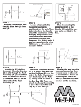
STEP 4. INSTALL FRONT
SUSPENSION
a. Adjust spring length to 18-1/2 in. (470 mm) with
adjusting nut.
b. Loosely install four 3/8 NC X 0.75 LG carriage
bolts (A) at the base of the vertical leg. Install bolts
from inside leg.
c. For ease of installation, secure suspension
assembly in configuration shown in illustration.
Slots (B) in plates should face cutterbar with cut-
outs (D) at the top and handle (E) hanging down
at back of assembly.
d. Position channel/spring subassembly (F) on bolts
(A) and slide subassembly into leg.
e. Attach top of subassembly to leg with four
3/8 NC X 0.75 LG carriage bolts (G). Install bolts
from inside leg. Tighten all hardware.
f. At the left-hand leg, pull handle (E) away from
spring to release the spring and position linkage in
top slot (H). Lower handle to lock.
F
G
H
E
18-1/2 in.
(
470 mm
)
B
E
D
FORWARD
A

SUSPENSION
169784 14 Revision A
STEP 5. INSTALL REAR
SUSPENSION
a. Loosely install four 3/8 NC X 0.75 LG carriage
bolts (A) at the base of the vertical leg. Install
bolts from inside leg.
b. Lift axle (B) and channel/spring subassembly (C),
and position lower end of subassembly (C)
into leg.
c. Position lower end of subassembly (C) on
bolts (A)
d. Slide subassembly (C) into leg.
e. Attach top of subassembly (C) to leg with two
3/8 NC X 0.75 LG carriage bolts (D) and smooth
face lock nuts in right side of leg, and two
3/8 NC X 1.0 LG carriage bolts (E) and smooth
face lock nuts in left side of leg. Install bolts from
inside leg
f. Tighten all hardware except bolts (E).
g. Pull handle (F) to release the spring and position
linkage in 4
th
slot (G) from the top. Lower handle to
lock.
h. Remove L-pin (H) from leg storage location and
install in transport lock position.
i. The right-hand fixed axle is now in transport
position.
A
A
C
E
D
B
F
G
H
H

REAR AXLES AND WHEELS
169784 15 Revision A
STEP 6. INSTALL REAR FIXED
AXLE
a. Position a 2x4 wooden block or equivalent
between the right-hand leg and draper to allow
installation of the support assembly.
b. Check that spacer (A) is installed in axle.
c. Position fixed axle assembly (B) in leg and align
mounting hole in axle with aft hole (C) in leg.
d. Remove bolt (D), washers, and nut from pivot
casting (E).
e. Position pivot casting assembly (E) on leg.
f. Install two 21/32 in. I.D. flat washers (F) under bolt
(D) head and install through leg and assembly (E).
g. Install four 21/32 in. I.D. flat washers (F) and
smooth faced locknut (G) on threaded end of bolt
(D). Do not tighten.
B
C
A
D
E
D
F
G
F
E
D

REAR AXLES AND WHEELS
169784 16 Revision A
h. Install two 5/8 NC X 1.25 LG carriage bolts (H)
and smooth faced locknuts in lower flange. Do not
tighten.
i. Install one 5/8 NC X 1.25 LG carriage bolt (J)
through top of assembly (E) and through upper
flange of leg. Secure with smooth faced locknut.
Do not tighten.
j. Install one 5/8 NC X 1.5 LG carriage bolt (K) and
smooth faced locknut through side of the leg. Do
not tighten.
k. Tighten the four carriage bolts and torque to 150
ft·lbf (203 N·m).
l. Tighten nut (G) on hex bolt (D) and torque to
160 ft·lbf (217 N·m).
m. Tighten nut (L) and torque to 160 ft·lbf (217 N·m).
H
K
J
E
G
D
L

REAR AXLES AND WHEELS
169784 17 Revision A
STEP 7. INSTALL REAR SWING
AXLE
a. Remove 5/8 NC X 4.5 LG bolt (A) from axle
support swivel (B). Ensure spacer (C) remains in
place. Make note of hardware orientation for
replacement in next step.
b. Position swing axle (D) on axle support swivel (B)
and attach with one 5/8 NC X 4.5 LG bolt (A), and
nut. Torque to 160 ft·lbf (217 N·m).
c. Set the swing axle perpendicular or slightly
forward of perpendicular to cutterbar.
d. Raise axle support (D).
e. Adjust gap (E) between cutterbar and axle support
(F) to 0.02-0.16 in. (0.5-4.0 mm) by loosening jam
nut (G) and turning adjuster bolt (H). Retighten
jam nut.
A
C
B
A
D
B
G
H
E
F

REAR AXLES AND WHEELS
169784 18 Revision A
STEP 8. CHECK AXLE
SUBASSEMBLIES
A. HUB PIVOT
a. Perform the following check to ensure that the
wheel hub pivot is snug while in the transport
position:
b. Check that hub pivot (A) is in transport position
and ensure that L-pin (B) has locked the hub.
c. Check hub pivot (A) for looseness.
d. If hub pivot (A) is snug, check that L-pin (B) can
move freely out of and into lock position (down).
e. If L-pin (B) is jammed, loosen jam-nut (C) and turn
adjuster bolt (D) until L-pin (B) can move. Hub
pivot (A) should be snug and L-pin (B) should
move freely when properly adjusted.
f. If hub pivot (A) is loose when L-pin (B) is engaged,
turn adjuster bolt (D) until hub pivot (A) is snug. L-
pin (B) should move freely when properly
adjusted.
g. Tighten jam nut (C).
B. LATCH ALIGNMENT
a. Move the swing axle (E) to field position.
b. Check alignment of latching system. Swing axle
(E) should freely engage latch (F) on fixed axle
(G). If necessary, align the latch as follows:
1. Loosen latch bolts (H) (four per axle) to allow
parts to adjust position for best fit.
2. Latch axles together in field position.
NOTE
It may be necessary to add washers (J) (not
supplied) between plates at top or bottom
bolts (H) on one of the axles to achieve
plate alignment for proper latching. Some
light grinding may also be necessary.
3. Tighten bolts (H) while axles are latched
together.
c. Check fit.
SWING AXLE
A
C
D
B
FIXED AXLE
A
C
D
B
G
E
F
H
H
J
H
/