Grace Company The Z44 Operating instructions
- Type
- Operating instructions
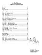
Grace Company The Z44 is a hand quilting frame equipped with the Professional Series Rails. It is a sturdy frame that can be used finished or unfinished. For extra protection, or to give it a finished look, you may seal, stain and/or finish the frame using a number of different applications. It has a lifetime limited warranty. This quilting frame is designed to make the entire process of hand quilting easier, from beginning to end. It is a versatile frame that can be used for a variety of quilting projects, from small to large.
Grace Company The Z44 is a hand quilting frame equipped with the Professional Series Rails. It is a sturdy frame that can be used finished or unfinished. For extra protection, or to give it a finished look, you may seal, stain and/or finish the frame using a number of different applications. It has a lifetime limited warranty. This quilting frame is designed to make the entire process of hand quilting easier, from beginning to end. It is a versatile frame that can be used for a variety of quilting projects, from small to large.


-
 1
1
-
 2
2
-
 3
3
-
 4
4
-
 5
5
-
 6
6
-
 7
7
-
 8
8
-
 9
9
-
 10
10
-
 11
11
-
 12
12
-
 13
13
-
 14
14
-
 15
15
-
 16
16
-
 17
17
-
 18
18
-
 19
19
-
 20
20
-
 21
21
-
 22
22
-
 23
23
-
 24
24
-
 25
25
-
 26
26
-
 27
27
-
 28
28
-
 29
29


Grace Company The Z44 Operating instructions
- Type
- Operating instructions
Grace Company The Z44 is a hand quilting frame equipped with the Professional Series Rails. It is a sturdy frame that can be used finished or unfinished. For extra protection, or to give it a finished look, you may seal, stain and/or finish the frame using a number of different applications. It has a lifetime limited warranty. This quilting frame is designed to make the entire process of hand quilting easier, from beginning to end. It is a versatile frame that can be used for a variety of quilting projects, from small to large.
Ask a question and I''ll find the answer in the document
Finding information in a document is now easier with AI
Related papers
-
 Grace Company The Z44 Operating instructions
-
Grace Company The A34 User manual
-
Grace Company Z44 New Millennium User manual
-
 Grace Company Machine Quilter User manual
-
 Grace Company The GMQ-Pro User manual
-
 Grace Company The EZ3 Operating instructions
-
 Grace Company The EZ3 Operating instructions
-
 Grace Company The A34 Operating instructions
-
-
 Grace Company Continuum Frame Operating instructions


Other documents
-
Greenlee Caster Installation - Job Box Manual User manual
-
-
 G.Skill FTB-3500C5-D Datasheet
-
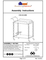 Furniture of America IDF-AC289 Installation guide
-
GYMAX GYM06904 User manual
-
 GYMAX GYM07433 User manual
-
Havis-Shields Van Slide Out Side Step KK-S-ST-SS User manual
-
Anova D1630C Assembly Instruction
-
Kmart 43164219 User manual
-
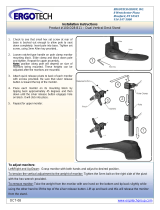 Ergotech Group 100-D28-B11 Installation guide


