Page is loading ...

Steam Generator
Installation and Operating Manual
STEAMPRO
TM
SteamPro

IMPORTANT SAFETY INFORMATION
READ ALL INSTALLATION INSTRUCTIONS
Jacuzzi Whirlpool Bath does not recommend prolonged periods of use of the steamer. Prolonged use of the steam
system can raise excessively the internal human body temperature and impair the body’s ability to regulate its
internal temperature (hyperthermia). Consult your physician about your safety and comfort before using the steam
system. Limit your use of steam to 10–15 minutes until you’re certain of your body’s reaction. A cooling shower spray
can be used simultaneously with the steam to assist in regulating your body temperature.
Alcohol and certain drugs or medications, such as tranquilizers, affect a person’s ability to withstand high temperatures
and may produce dangerous side effects. Don’t use alcohol or drugs when using steam.
The elderly, the infirm, and children should not use the steamer unattended. Pregnant women and people with heart
conditions should consult their physicians before using the steamer.
The wet surfaces of steam enclosures can be slippery. Use care when entering and exiting.
Do not place or use electrically connected devices, such as television, radio, or stereo speakers, lights, hair dryers,
or telephones, within 1.5 m (5 feet) of a steam enclosure, shower, or bath.
Read and follow manufacturer’s safety information with all optional equipment.
The steam head is hot. Do not touch the steam head or the steam within one foot distance of the head or surfaces
surrounding the steam head.
Do not block or obstruct the steam head in any manner.
Do not store or use flammable liquids near the steam generator.
Save These Instructions for Future Use.
Inspection and Shipping Claim
Check for shipping damage upon receipt of the product. Jacuzzi Whirlpool Bath is not responsible for damage to the
product sustained during shipping. If damage is evident before unpacking, see instructions regarding shipping claims
on the outside of the carton and immediately file a claim with the carrier.
Once the product has been removed from the carton and before it is permanently installed, check the parts completely
for damage resulting from shipping or handling. All Jacuzzi Whirlpool Bath products are factory tested for proper
operation and watertight connections prior to shipping. If problems are detected, immediately notify your Jacuzzi
Whirlpool Bath dealer or Authorized Service Agent, or call Jacuzzi Whirlpool Bath, 800–363-0251, for Warranty
Service.
NOTE: Damage or defects which could have been discovered and repaired prior to installation and which are claimed
after final installation of the product are excluded from our warranty.
Owner’s Record
Date Purchased _________________________________________________________
Purchased From _________________________________________________________
Installed By _____________________________________________________________
Serial Number _________________________________ Model #
(The serial number is located on the end of the steam generator)

Contents
Installation of Steam Generator
Specifications ______________________________________________________________________________ 1
How to Select Generator Size and Electrical Requirements ___________________________________________ 2
Locating the Steam Generator _________________________________________________________________ 3
Room Construction and Ventilation _____________________________________________________________ 3
Plumbing Instructions and Cautionary Notes on Installation __________________________________________ 4
Plumbing Diagram___________________________________________________________________________ 5
Steam Head Installation for Various Wall Surfaces _______________________________________________ 6, 7
Automatic Drain Valve Installation (Optional) ______________________________________________________ 8
Steam Controls—Operating Instructions and Installation Methods
Steam Control Options _______________________________________________________________________ 9
Steam Control by 30 Minute ON/OFF Control ____________________________________________________ 10
Rough-In and Installation of Temperature Controls _____________________________________________ 11, 12
Operating Instructions
Steam Control by 30 Minute Temperature Control _________________________________________________ 13
Steam Control by Digital Time and Temperature Control ____________________________________________ 14
Service ___________________________________________________________________________________ 15
Troubleshooting __________________________________________________________________________ 16, 17
Wiring Diagram _____________________________________________________________________________ 18
Warranty _______________________________________________________________________________ 19, 20
GENERAL DESCRIPTION
SteamPro™ steam generators from Jacuzzi Whirlpool Bath are designed for compact size and easy installation and
provide full, high volume steam for luxurious steam bathing. The accessories and control options have been designer
for easy plug-in installation and function with all sizes of SteamPro™ generators. For residential use only.
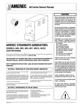
SPECIFICATIONS
AVAILABLE MODEL DIMENSIONS PACKAGED
SIZES NUMBER LxWxH SHIP WEIGHT
5kW S064000 16½”x 6¼”x 13” 27 lbs.
7kW S062000 16½”x 6¼”x 13” 28 lbs.
10kW S060000 16½”x 6¼”x 13” 28 lbs.
SteamPro
13"
6¼"
16½"
29½"
29½" FOR PLUMBING
CLEARANCE WITH
AUTOMATIC DRAIN
VALVE.
(23" WITH MANUAL VALVE
IF VALVE IS INSTALLED
HORIZONTALLY. 21"
WITH MANUAL VALVE IF
ELBOW IS ADDED TO
INSTALL VALVE
VERICALLY WITH DRAIN
LINE.)
1

How to Select Generator Size
Step 1. Determine cubic footage of steam enclosure: multiply LENGTH inches x WIDTH inches x HEIGHT inches
to find cubic inches. Divide cubic inches by 1728 to determine cubic feet.
Step 2. Find steam enclosure size within the ranges shown on the chart for the supply voltage
(240 VAC or 208 VAC).
Step 3. Consider material and climate: If the steam enclosure is constructed of tile or marble or if the steam
enclosure is against poorly insulated outside walls in a cold climate, select the next higher or highest kW
size of steam generator available. Natural stone such as marble may reduce the cubic cpacity by as
much as 50%.
Electrical Requirements
All SteamPro generators operate at 208 or 220 to 240 VAC at 50 or 60 Hz. Circuit is to be single phase 3-wire (two
conductors at line voltage and one ground conductor must be provided). Bond the SteamPro generator with a #8
minimum gauge solid copper wire from the bonding clamp at the unit to the house electrical panel or approved local
ground. An approved ground may be an 8 foot long ground rod (3 meter length earth rod), a plate electrode, or other
acceptable bond. Check your local building code for requirements.
Caution: Without proper grounding and bonding, a system malfunction may cause fatal shock.
INSTALLATION
ecivreSlacirtcelEesahP-elgniS
deriuqeR
rewoProtareneG
egatloVtagnitaR
erusolcnEfoeziS
)teefcibuc(
ORPMAETS
0425/
000460S
)01#(ERIW3PMA03CAV042042@Wk0.5011-06
)01#(ERIW3PMA03CAV802802@Wk57.308-06
ORPMAETS
7/042
000260S
)8#(ERIW3PMA04CAV042042@Wk0.7022-011
)8#(ERIW3PMA04CAV802802@Wk52.5051-08
ORPMAETS
01/042
000060S
)6#(ERIW3PMA06CAV042042@Wk0.01004-022
)6#(ERIW3PMA06CAV802802@Wk5.7032-051
Specifications and Sizing of the Steam Generator for the Room
2

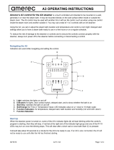
Locating the Steam Generator
The steam generator must be installed upright and level. The steam generator must be located within a 25 foot
maximum steam line run to the steam head AND within the 25 foot control wire length to any controls. It may stand
attached to a horizontal base or to a wall. For wall mounting, use “keyhole” slots on a cabinet back to slip over screw
heads and install a wood cleat or shelf to the wall at the bottom of the unit to help support the bottom. Add a cleat at
the top to keep the unit in place.
Install the steam generator indoors only and in a dry location that will not be subject to freezing. If exposure to
freezing can not be avoided (e.g., seasonal-use homes), the optional automatic tank drain down valve must be
installed. Turn off the power and water supply to the unit if it will not be used for an extended period of time.
Room Construction and Ventilation: Important
The room in which the steam generator is to be located must be constructed of materials that can withstand excessive
amounts of moisture and condensation. Large amounts of steam can be released into the room when the enclosure
door is opened. Providing natural or forced ventilation of the room will help maintain comfort and minimize moisture
damage to the building. Jacuzzi Whirlpool Bath is not responsible for damage resulting from excessive moisture.
Consult an architect or engineer for aid in designing your room structure.
INSTALLATION
HEATED ATTIC
STEAM
ENCLOSURE
ADJOINING
CLOSET
BASEMENT
INSIDE VANITY
OR CABINET
3

Plumbing Instructions and Cautionary Notes on Installation
Minerals in the water or poor water quality can shorten the life of the steam generator or cause erratic operation if
the tank is not drained regularly. Drain the tank frequently. Jacuzzi Whirlpool Bath also strongly recommends
purchasing and installing the optional drain down valve. See the important note below. The tank will be drained
automatically after each use after the water temperature lowers. Water filters and other conditioners are strongly
recommended if the water is of poor quality.
Guard against possible contact with hot steam pipes and other plumbing.
Maximum run of the steam pipe is 25 feet. The steam pipe should be insulated. This will reduce condensation in
the steam line and will increase efficiency. Use only copper and brass pipe and fittings, 1/2 inch minimum.
Install a water supply shutoff valve where it is easily accessible.
The water supply pipe should be attached to cold supply. Do not use a saddle or piercing type connection for the
steam unit water supply.
Apply thread compound sparingly to fitting threads such that excess compound does not dislodge and restrict the
copper pipes or filter screen. Flush lines before making connections to the generator.
When tightening or loosening fittings, always use a backup wrench to hold the adjacent fitting.
Caution: Do not install any valves or create restrictions in the steam line. Do not construct any dips or valleys
in the steam line as condensation will accumulate in these and block the pipe with water. Pitch the steam line
such that condensation will run to the steam generator (preferable) or to the steam head.
Important Note About Tank Drain Selection:
Jacuzzi Whirlpool Bath strongly recommends purchasing and installing the optional Automatic Tank Drain Valve
for the steam generator. This drain valve prevents standing water from remaining in the tank between uses.
The Automatic Tank Drain Valve must be installed where the steam generator may be exposed to freezing
temperatures, e.g., in seasonal-use homes. (Water supply lines and water solenoid valve must not be allowed to
freeze.) This option prevents standing water from remaining in the tank. The tank will be automatically drained
through this valve when the water has cooled.
Read all warranty provisions before selecting a manual drain valve or the automatic drain down option.
INSTALLATION
4

INSTALLATION
STEAM UNIT TO BE LEVEL AND UPRIGHT SEE
PAGE 5 FOR SUGGESTED LOCATIONS
WATER SUPPLY
WITH SHUT-OFF
VALVE (3/8 OR 1/2
INCH COPPER)
TO STEAM HEAD SEE
PAGES 8 AND 9 FOR STEAM
HEAD PLUMBING AND
INSTALLATION FOR VARI-
OUS WALL SURFACES.
STEAM PIPE 1/2 INCH
(MINIMUM SIZE) COPPER.
25 FOOT TOTAL MAXIMUM
RUN. DO NOT PLACE ANY
VALVES OR DIPS IN THIS
LINE. PIPE INSULATION
RECOMMENDED
*SHOWN WITH OPTIONAL
AUTOMATIC DRAIN VALVE
(SEE PAGE 10)
TANK DRAIN LINE. INSTALL
SITE DRAIN OR OTHER
DRAINAGE METHOD AS
REQUIRED BY LOCAL
CODES (WITH AUTOMATIC
DRAIN OPTION, WATER
DISCHARGED IS LESS THAN
140°F).
MANUAL TANK DRAIN VALVE.
LOCATE IN AN AREA EASILY
ACCESSIBLE TO ALLOW
FREQUENT DRAINING.
1/2 INCH MINIMUM
COPPER
NOTE: ALL COPPER PIPE
SIZES ARE TO BE INDUSTRY
NOMINAL SIZES. PLUMBING
AND FITTINGS ARE NOT
PROVIDED UNLESS NOTED
OTHERWISE.
*TANK DRAIN WITH MANUAL
VALVE (MANUAL DRAIN VALVE
IS PROVIDED WITH STEAM
GENERATOR)
PRESSURE RELIEF VALVE 3/4 NPT
(PROVIDED WITH STEAM GENERATOR)
REDUCTION FROM 3/4 NPT TO 1/2 NPT
PERMITTED
PRESSURE RELIEF VALVE DRAIN LINE.
DRAIN LOCATION AND METHOD AS
REQUIRED BY LOCAL CODES. (TO BE
1/2 INCH MINIMUM SIZE COPPER)
Plumbing Diagram
SteamPro
SEE CHART ON
PAGE 4 FOR
REQUIRED
WIRE SIZE.
5

INSTALLATION
Steam Head Installation for Various Wall Surfaces
Jacuzzi Whirlpool Bath recommends that the steam shield be used for all steam head installations. The steam shield
must be installed if the steam head is located on acrylic (or other plastic) wall surfaces or above a bath rim. The steam
head is to be installed at 18 inches minimum height above the floor or shower base.
The steam head is to be installed at 10 inches minimum above a bath rim.
Caution: Consult the manufacturer of the enclosure, shower, or bath unit to verify the suitability of the material for
use with steam.
6

INSTALLATION
10 kW Steam Generator with Two Steam Heads
Two steam heads may be installed with the Model E210000 Steam Generator, if desired. This will reduce the
sound level of the exiting steam and will provide more even steam distribution and less heat concentration in
larger steam enclosures.
POSITIONING TWO STEAM HEADS WITH MODEL E210000 STEAM GENERATION (10 kW)
3' MINIMUM
7

1. Apply thread compound sparingly to male threads
on fitting A. (Keep thread compound from entering
the valve.)
2. Using a backup wrench to hold fitting A, thread
valve assembly onto fitting and tighten. Valve
outlet must point as shown.
3. Make certain power is disconnected. Remove
top cover.
4. Remove and discard plug from hole B .
5. Feed through hole B. Connect to terminal block 2
(TB2) on circuit board.
6. Locate strain relief bushing C. Snap strain relief
bushing C into hole B.
7. Replace cover.
INSTALLATION
Automatic Drain Valve Installation (Optional)
Important Note About Tank Drain Selection:
Jacuzzi Whirlpool Bath strongly recommends purchasing and installing the optional Automatic Drain Valve for the
steam generator. This valve prevents standing water from remaining in the tank between uses.
This valve must be installed where the steam generator may be exposed to freezing temperatures, e.g., in seasonal-
use homes. This valve automatically drains the tank when the water has cooled.
POWER ENTRY
HOLE B
BUSHING C
(PROVIDED)
TB2
OPTIONAL AUTOMATIC DRAIN
VALVE ASSEMBLY
FITTING A 1/2 NPT
(PROVIDED)
ALTERNATE VERTICAL
AUTOMATIC DRAIN
VALVE INSTALLATION
8

INSTALLATION
Steam Controls—Available Installation Methods
Various control packages are available for use with the steam generator. The following instructions (A–C, pages
12 - 16) describe the different installations. Select one of the following control options:
A. ON/OFF 30 minute control. B. 30 minute temperature control. C. Digital time and temperature
control.
9
S061827
S061829
(no sensor, no cable
S083827
S083827
(with sensor and cable)
S063827
S068829
(with sensor and cable

INSTALLATION
APPLY SEALANT
(100% SILICONE CAULK)
1-3/4" DIAMETER HOLE
IN FINISHED WALL
(OPTIONAL NUT INSTALLATION
IF BACK OF WALL IS
ACCESSABLE)
A. STEAM CONTROL BY 30 MINUTE LOW VOLTAGE ON/OFF CONTROL.
THIS LOW VOLTAGE CONTROL CAN
BE LOCATED INSIDE OR OUTSIDE
THE STEAM ENCLOSURE
1. Control cable rough-in:
The low voltage control can be mounted up to 75 feet
from the generator either inside or outside the steam
room. (A 25’ cable provided.) Also, see # 4 Optional
Secondary Generator Control. String (3) 18 to 22 AWG
solid wires from the control location through 1/2" holes in
the wall studes or ceiling joists to the generator.
Note: 1) Do not staple through or damage wires,
2) Label or color code wires for proper TB1
to R30i orientation. See diagram.
2. Control cable at the generator
Route control wires through the generator CONTROL
WIRING ENTRY and appropriate strain relief. Connect 3
wires to terminal block TB-1 on the printed circuit
assembly, as shown in diagram.
3. Install generator control (R30i)
The low voltage control can be mounted directly to a
finished wall either inside or outside the steam room.
Using a 1-3/4" hole saw, drill a hole in the finished wall
where the control is to be mounted (the control wires
should already be roughed-in to this location). Locate the
control wires, pull them out through the 1-3/4" hole and
plug the 3 wires into the connector on the back of the
control housing, as shown in diagram. Run a bead of
100% silicone caulk around the perimeter on the back of
the control housing. See diagram. Insert the control into
the wall cavity.
4. Optional second generator control
As an option, a second R30i control can be installed with
the generator to provide ON/OFF control both inside and
outside the steam room. The second control should be
installed as described in paragraphs 1 & 3, with the
second control wire plugged into the same connector TB1
connector as the first control on the PCA.
To prepare steam generator:
1. Make certain that power is disconnected.
Remove cover.
2. Remove and discard plug from hole A.
3. Feed wire through hole A and connect to
TB1 on the circuit board.
4. Locate strain relief bushing 1" from
stripped end of cable jacket with the two
connectors. Snap strain relief bushing B
into hole A.
5. Replace cover.
SK1
SK4
SK3
TB1
(3) GREEN
(2) RED
(1) WHITE
GREEN (3)
RED (2)
WHITE (1)
LOW VOLTAGE CONTROL
WIRE (25') IS PROVIDED
FOR 5 VOLT DC SWITCH
CONNECTION TO STEAM
GENERATOR. NO
ADDITONAL ELECTRICAL
SUPPLY OR WIRING
REQUIRED.
BUSHING B
HOLE A
10

INSTALLATION
GENERAL INSTRUCTIONS FOR TEMPERATURE CONTROL MODELS
1. Control Cable Rough-in
The low voltage control can be mounted up to 25
feet from the generator either inside or outside the
steam room, also see #6 optional secondary digital
generator control. String the 25' cable from the
control location through 1/2" holes in the wall studs
or ceiling joists to the generator. Note: Do not staple
through or damage cable. Use factory supplied
cables only. Optional for tile rooms, a 1 gang rough-
in box may be installed at the desired control
mounting location. A mounting plate with proper 2"
diameter hole is included with the control kit. Tile up
to the 2" hole in the mounting plate.
2. Temperature Sensor Rough-in
It is recommended that the sensor be mounted in
the steam room 6" from the ceiling, but not directly
over the steam dispersion head or more than 7 feet
above the floor. String the sensor cable from the
sensor location through 1/2" holes in the wall studs
or ceiling joists to the generator location. Leave 12"
of slack at the sensor location. Note: Do not staple through or damage cable. Use factory supplied cables only.
3. Electrical Rough-in
Size wire for the generator as indicated by the Electrical Information Chart on page 4. Use correct size and type to
meet electrical codes. Leave 4 feet of slack wire at generator location for finish hookup. Connect the generator to a
dedicated circuit breaker. A GFI device is not required by UL. One may be installed if required by local codes or the
owner. A GFI device will tend to nuisance trip due to heater element aging.
4. Electrical finish
Materials (locally available):
- 3/4" Strain relief for supply wire.
A. Route the copper supply wire with appropriate strain relief through the hole marked POWER ENTRY.
B. Connect the supply wires to the terminal block marked L1 and L2.
C. Connect the ground to the ground lug.
6" MIN -
7'
MAX
TEMPERATURE
SENSOR
STEAM
CONTROL
TEMPERATURE
SENSOR
CABLE
WALL
DECORATIVE
CONTROL COVER
PLATE
CONTROL
HOUSING
CONTROL
HOUSING
SEALANT
(MUST FILL GROUT
LINE FOR TILE
WALLS).
CONTROL
HOUSING
DECORATIVE CONTROL
COVER PLATE
CONTROL HOUSING
MOUNTING SCREWS
2" DIAMETER
HOLE IN FINISHED
WALL
MOUNTING
BRACKET
(DO NOT OVER
TIGHTEN)
CONTROL
CABLE
11

INSTALLATION
5. INSTALL GENERATOR CONTROL
The low voltage control can be mounted directly to a
finished wall either inside or outside the steam room.
Using a 2" hole saw, drill a hole in the finished wall where
the control is to be mounted (the control cable should
already be roughed-in to this location). Locate the control
cable, pull it out through the 2" hole and plug it into the
connector on the back of the control housing. With the
decorative cover removed, screw the two 3" control
housing mounting screws 1/4" into the mounting bracket.
See diagram. Run a bead of 100% silicon caulk in-
between the 2 ridges around the perimeter on the back
of the control housing. See diagram. Insert the mounting
bracket into the wall cavity by first pushing with the control
housing and then with a hard flat surface on the control
housing mounting screws which extend out through the
control face. Once the mounting bracket has been
inserted into the finished wall, center the control and
tighten the mounting screws to draw the control housing securely against the finished wall. Do not over tighten the
mounting screws. Install the decorative cover plate by sliding the top of the cover plate over the tab on the top of the
control housing and pushing on the bottom of the cover plate to complete the snap fit. See diagram. Route the
generator end of the control cable through the generator hole marked CONTROL WIRING ENTRY using the strain
relief provided. Plug the control cable into the connector on the printed circuit board assembly. Insert cable into
connector SK1 if a 30 minute temperature control is used or connector SK3 if a digital control is used. See diagram.
6. OPTIONAL SECONDARY GENERATOR CONTROL
As an option, a second digital control can be installed
with a generator to provide ON/OFF control both inside
and outside the steam room. The second control should
be installed as described in paragraphs 1 & 5, with the
second control cable plugged into connector SK4 for the
digital control on the printed circuit board assembly. See
diagram.
7. INSTALL TEMPERATURE SENSOR
The temperature sensor should be mounted 6" below the
ceiling, inside the steam room, but not directly over the
steam dispersion head or more than 7 feet above the
floor. Using a 7/8" hole saw, drill a hole in the finished
wall where the sensor is to be mounted (the sensor cable
should already be roughed-in to this location). Locate the
sensor cable, pull it out through the hole and plug it into
the temperature sensor. It is best to tape the sensor and cable connection together to avoid disconnection inside the
wall. Apply silicon caulk as shown in diagram and insert the sensor in the hole. An optional trim ring is included with
the sensor. If the 7/8" hole is jagged or is cut too large the trim ring may be used to cover the exposed edges. See
diagram. Make sure that the sensor probe is pointing down once installed. Tape the sensor in place while the silicone
hardens. Route the generator end of the sensor cable through the generator hole marked CONTROL WIRING
ENTRY using the control cable strain relief. Plug the sensor cable into the connector marked J4 on the printed circuit
board assembly. See diagram.
SILICONE
CAULK
TEMPERATURE
SENSOR
WALL
7/8" HOLE
SENSOR
CABLE
PIGTAIL
PROBE MUST
BE POINTED
DOWN
OPTIONAL
TRIM RING
J4
SK4
SK1
SK3
TB2
STEAM CONTROL PLUGS
PRIMARY (SK1) 30 MINUTE TEMP (1 BUTTON)
PRIMARY (SK3) DIGITAL (2 BUTTON)
SECONDARY (SK4) SECOND DIGITAL
STEAM
CONTROL
TEMPERATURE
SENSOR
TEMPERATURE SENSOR
PLUG (J4)
OPTIONAL AUTOMATIC
DRAIN CONNECTION
12

OPERATION
B. 30 MINUTE TEMPERATURE CONTROL
The 30 minute temperature control features a 30 minute press on timer lighting
up the word "STEAM" and a thermostatic control preset to reach 120 degrees
Fahrenheit. The digital control can be mounted either inside or outside the
steam room. The preset temperature can be adjusted in a range between
100 degrees and 125 degrees Fahrenheit. Once the set temperature is
reached the ''soft steam'' feature automatically engages cutting steam
production back to a single element to provide softer billowing steam during
more of the steam bath. If the steam room temperature drops more than 5
degrees both elements will automatically engage.
Operation of Your 30 Minute Temperature Control
1. Be sure the power circuit and water supply to the generator are on.
2. Firmly press the ON/OFF button on the control until the word “STEAM” lights up.
3. The generator should produce steam in 5 to 10 minutes and will turn off automatically in 30 minutes. You may
also press the control a second time to turn off the “STEAM” light and shut down the generator.
4. If you wish to change the preset temperature see the instructions in below.
Temperature Adjustment
1. To adjust the set temperature remove the snap-on decorative control cover by lifting from the bottom as shown
in diagram.
2. Using a small slotted screw driver turn the adjustment pot in the desired direction. See diagram. One quarter
turn equals approximately 5 degrees of temperature change. Caution: Over stressing the adjustment pot can
damage the control.
3. Snap the control cover plate back on by sliding the top of the cover plate onto the control housing and pushing
on the bottom of the control cover plate. See diagram. The new temperature setting will become effective the
next time the steam is turned on.
2
WALL
DECORATIVE CONTROL
COVER PLATE
CONTROL
HOUSING
13

OPERATION
C. DIGITAL TIME AND TEMPERATURE CONTROL
The digital control features an adjustable 60 minute time and temperature
control with digital display. The actual room temperature and time remaining
are alternately displayed every 5 seconds. The primary control can be
mounted either inside or outside the steam room and an optional secondary
control is available to mount in an alternate location. The temperature can
be adjusted in a range between 100 degrees and 125 degrees Fahrenheit
with an initial default of 120 degrees. Once the set temperature is reached
the ''soft steam'' feature automatically engages cutting steam production
back to a single element to provide softer billowing steam during more of
the steam bath. If the steam room temperature drops more than 5 degrees
both elements will automatically engage.
Operation of Your Digital Time and Temperature Control
1. Be sure the power circuit and water supply to the generator are on.
2. Press the ON/OFF button on the control until the temperature is displayed.
3. The generator should produce steam in 5 to 10 minutes and will turn off automatically in 60 minutes or less
depending on the set time. The control will alternately display time remaining and the actual temperature at
the sensor in your steam room every 5 seconds.
4. To change the time setting press and hold the TIME button on the control. Continuing to hold the button will
cause the time to increase in 5 minute increments from the prior setting. At 60 minutes the time setting will
scroll backwards to 5 minutes. To shut down the generator press the ON/OFF button.
5. To change the preset temperature setting press and hold the TEMP button on the control. While continuing to
hold the button, the temperature display will increase in 1 degree increments from the prior setting to 125
degrees Fahrenheit. At 125 degrees Fahrenheit the temperature setting will decrease in 1 degree increment to
the lowest setting, 100 degrees Fahrenheit.
6. The TIME and TEMP set points are remembered for your next bath unless power to the steam generator is lost.
14

SERVICE
Description of SteamPro Steam Generator
The SteamPro series generator is the latest in modern steam generator design. The SteamPro steam generator uses a
printed circuit assembly to monitor and control all the equipment needed to produce steam. The system has three functions:
a timer that controls the length of the steam bath; the operating water level is monitored and controlled; and the heating
elements are protected by a minimum water level sensor. The generator is compartmentalized into wiring, control and
tank sections. The elements can be removed through an access opening on the service side.
Maintenance of SteamPro Generators
Maintenance of the SteamPro generator includes flushing the unit periodically and visually inspecting for water leaks.
Whenever the generator is opened all wiring should be inspected for any signs of overheating. All electrical connections
should be checked for tightness.
Repair of SteamPro Generators
A. ELEMENT REPLACEMENT: Disconnect power from the unit. Drain the tank. Open the front and HEATING
ELEMENT ACCESS covers. Note the wire connections. See diagram. Remove the element wires. Using a hot
water element socket, remove the element. To install a new element, mount a new element gasket on the element.
Clean the element port and add a light coat of Rectorseal No. 5 pipe thread compound to the threads. Insert and
hand tighten the element-gasket combination. Notice the element end orientation as shown in diagram. Tighten
the element until the orientation is the same as diagram, ± 15°. The gasket should be set and tight but not
deformed to a rounded or bulbous appearance. If the drain valve was removed reinstall it. Reconnect the wiring.
Test the unit. Check for leaks at the element. Replace the front cover and the HEATING ELEMENT ACCESS
cover.
B. PRINTED CIRCUIT REPLACEMENT: Disconnect power from the unit. Remove the front cover. Note where the
blue wire is connected to the triple pronged water level probe. Disconnect all three wires from the water level
probe. A u-clip on the shelf is retaining these three wires. Slightly bend this u-clip to free the three wires. Discon-
nect the two blue wires from the water solenoid and (3) wires connected to TB1. Note and tag the position of all
wires that plug into the printed circuit assembly mounted relays. Remove all the wires from the relays. When
removing these wires pull on the connector and not the wire. Five screws hold the board in place. Remove all five
screws. The printed circuit assembly can now be removed. To install the board reverse this procedure. Test the
unit.
IMPORTANT
The blue wire connected to "L" and "P3" on the PCA must be connected
to the shortest of the three level probes.
C. WATER SOLENOID REPLACEMENT: Disconnect power from the unit. Turn the water supply OFF. Disconnect
the water supply from the water solenoid valve. Remove the front cover. Remove the two blue wires from the water
solenoid valve. Rotate the self-tightening hose clamp so it can be loosened with a pair of pliers. Squeeze the
clamp and move it down towards the shelf and off the valve outlet tube. Remove the two 1/4" - 20 hex head bolts
and lock washers that attach the valve to the chassis. Pull the valve off the rubber fill hose. To install the valve,
reverse these instructions. Test the unit.
D. LEVEL PROBE REPLACEMENT: Disconnect power from the unit. Remove the front cover. Note where the blue
wire is connected to the triple pronged water level probe. Disconnect all three (3) wires from the water level probe.
Using a 1-1/4" box wrench, remove the level probe. Install a new level probe. Tighten until the bottom of the plastic
nut is 1/8" to 3/8" inch above the top of the port. Reattach the three (3) wires. Test the unit.
IMPORTANT
The blue wire connected to “L” and “P3” on the PCA must be connected
to the shortest of the three level probes.
IMPORTANT
The level probe may be extremely tight. Damage to the insulation or chassis may result unless
the tank is properly blocked or supported during probe removal or installation. It may be neces-
sary to completely disconnect and disassemble the generator.
15

TROUBLESHOOTING
There are no user serviceable parts in the Generator. All repair should be performed by a qualified service person.
For additional assistance or the factory authorized service person nearest you call the Service Department at 1-800-
363-0251. The Trouble Shooting Guide below is meant as a general aid only. Follow ACTION TO BE TAKEN in order
until the problem is resolved. Where replacements or repairs are indicated, see the appropriate paragraph of SERVICE
SECTION.
SMOTPMYSSESUACELBABORPNEKATEBOTNOITCA
t'nowlortnoC
"NO"nrut
thgillortnoC(
.)ffo
on(deilppusrewopreporpmI
.)rewop
.detcetnnocylreporpmilortnoC
ylbmessatiucricdetnirp"ACP"
.ytluafsi
.ytluafsielbaclortnoC
.ytluafsilotnoC
."NO"sirekaerbtiucricerusekaM.a.1
"ACP"ehtnosesufowtehtssorcaegatlovehtkcehc,retemtlovagnisU.b
.V042/V802ebdluohsegatloV.ylbmessatiucricdetnirp
#ssuBhtiwecalper,nwolbera)s(esuffI.ACPehtnosesufkcehC.c
llac-niagaswolbesufehtfI.esuftnelaviuqero001/51LDM
.tnemtrapeDecivreS
.5-6noitceSrepdellatsni)s(lortnockcehC.2
.tnemtrapeDecivreSllac-ylbmessatiucricdetnirpACPecalpeR.3
.tnemtrapeDecivreSllac-elbaclortnocecalpeR.4
.tnemtrapeDecivreSllac-lortnocehtecalpeR.5
."FFO"lortnoC
)ffothgillortnoC(
tuhst'nowretaW
tuosnurdnaffo
maetsehtfo
.daeh
kcutssievlavdionelosretaW
.nepo
ylbmessatiucricdetnirp"ACP"
.ytluafsi
.3petsotog,spotsretawehtfI.rotarenegehtotrewopffonruT.1
,naelc,elbmessassid,evlavdionelosretawehtevomeR.a.2
.noitareporeporprofkcehcdna,elbmessa-er
.tnemtrapeDecivreSllac-evlavecalpeR.b
.tnemtrapeDecivreSllac-ylbmessatiucricdetnirp"ACP"ehtecalpeR.3
."NO"lortnoC
thgillortnoC(
t'nowretaW)no
snurdnaffotuhs
maetsehtfotuo
.daeh
ylbmessatiucricdetnirp"ACP"
.ytluafsi
eulbehtneewtebnoitcennoC
eborplevelretawehtdnaeriw
.ytluafsi
.dednuorgylreporpmitinU
.eborplevelretawehtotdehcattaylreporpsieriweulbehttahtkcehC.1
.dednuorgylreporpsirotarenegehttahtkcehC.2
.ylbmessatiucricdetnirp"ACP"ehtotseriwdnuorgneergehtkcehC.3
.tnemtrapeDecivreS-ylbmessatiucricdetnirp"ACP"ehtecalpeR.4
"NO"lortnoC
thgillortnoC(
knaT,)no
.deniard
.llift'nowtinU
)?ffodenrut(deilppusretawoN
.evlavdionelosretawdeggulP
.ytluafsievlavdionelosretaW
ylbmessatiucricdetnirp"ACP"
.ytluafsi
.ytluafsieborpleveL
.evlavniarddesolcrofkcehC.)"no"evlavylppuS(ylppusretawreporprofkcehC.1
ehtecalperronaelc,slliftinuehtfI.eborplevelehtmorferiweulbehtevomeR.2
.eborplevel
edils,dionelosevlavretawehttA.eborplevelehtoteriwtsetrohsehttcennoceR.3
dionelosehtnoseborpretemtlovehttegothguonerotcennoceulbehtkcab
,/V802tonsitifI.slanimretdionelosehtssorcaegatlovehterusaeM.slanimret
deecorpdnuofsiV042/V802fI.ylbmessatiucricdetnirpehtecalperV042
.5&4spetshtiw
rofkcehcdna,elbmessaer,naelc,elbmessasid;evlavdionelosretawevomeR.4
.noitareporeporp
.tnemtrapeDecivreSllac-evlavdionelosretawehtecalpeR.5
ylnOniarDotuA(
)snoitallatsnI
denrutlortnoC
knat"FFO"
niardtonseod
setunim52retfa
dezirotomdna
syatsevlavniard
.desolc
ylbmessatiucricdetnirp"ACP"
.ytluafsi
deggolcebyamevlavniarD
.muiclachtiw
.depsalesahsetunim52erusekaM.a.1
."ACP"ecalpersnepoevlavniardfI.seriwevlavniardtcennocsiD.b
.naelcdnaevlavniardelbmessasiD.a.2
noitulosgnimiledgnisuknatnaelC.b
16

TROUBLESHOOTING
SMOTPMYSSESUACELBABORPNEKATEBOTNOITCA
."NO"lortnoC
)nothgillortnoC(
.maetst'nowtinU
tilmaetS:etoN
roylidaets
ylreporppmeT/emiT
latigiDnodeyalpsid
yalpsiD
.yletelpmocdelliftonsahtinU
.tuotnrubstnemelegnitaeH
.ytluafeborpleveL
siylbmessatiucricdetnirp"ACP"
.ytluaf
."FFO"lortnocehthsuP.a.1
.yletelpmocniardotknatgniwollaevlavniardehtnepO.b
.evlavniardehtesolC.c
."NO"lortnocehthsuP.d
retfasdnoces02nihtiW.esionkcilcarofnetsil,gnillifnigeblliwtinU.e
ehtetacidnilliwsihT.ffotuhslliwllifretaweht,draehsiesionkcilc
:SMOTPMYSeeS-lliftonseodknatehtfi,3petsotoG.llufsiknat
."pullift'nowtinU"
ehtdnuorgyliraropmet,draehtonsawkcilcyalerehttubdellifknatehtfI.2
ehtecalper,dednuorgsieborphcaesadraehsikcilcehtfI.seborpgnolowt
tiucricdetnirp"ACP"ehtecalperdraehtonsikcilcehtfI.eborplevel
.ylbmessa
esionkcilcehtdnadellifsahknatehttahtdenimretedneebsahtiretfA.3
,retemtlovagnisU.lenapsseccatnemelegnitaehehtevomer,draehsaw
eht-tnemelegnitaehhcaenoseriwowtehtneewtebegatlovehtkcehc
rofyrotcafehtllacdnuofsiegatlovreporpfI.V042/V802ebdluohsegatlov
-margaidgniriwkcehc-dnuofsiegatlovonfI.stnemelegnitaehtnemcalper
.tnemrapeDecivreSllac
."NO"lortnoC
lortnoClatigiD
"100E"syalpsid
.detcennoctonrosneserutarepmeT detnirp"ACP"ehtno4JotdetcennocsielbacrosnesehttahtkcehC.1
.ylbmessatiucric
.rosneserutarepmetehtotnoitcennocelbacehtkcehC.2
.tnemtrapeDecivreSllac-elbacro/dnarosnesecalpeR.3
."NO"lortnoC
lortnoClatigiD
"200E"syalpsid
.detrohselbacrorosneserutarepmeT .erutcnupelpats/lianmorfegamadrofelbacrosneskcehC.1
.sdnartseriwdesopxe/deyarfrofsdneelbacrosneskcehC.2
.tnemtrapeDecivreSllac-elbacro/dnarosnesecalpeR.3
."NO"lortnoC
lortnoClatigiD
"300E"syalpsid
.detcennocylreporpmilortnoC ehttadnalortnocehttanideggulpylreporpsielbaclortnocehttahtkcehC.1
ffonruT.ACPehtnorotcennoc3KSyramirpotlortnoClatigiD.rotareneg
reporprofkcehC.nokcabnrutnehtetunim)1(enotiaw,ylppusrewop
lortnocevomer,ylppusrewopffonrutdeyalpsidllitssi"300E"fI.noitarepo
dnaylppusrewopnonruT.rotcennoc4KSyradnocesotnigulpdnaelbac
llacdnarewopffonrutdeyalpsidllitssi"300E"fI.noitareporeporprofkcehc
.tnemtrapeDecivreS
."NO"lortnoC
lortnoClatigiD
"º>>>"syalpsid
.°231revoerutarepmethtabmaetS
.ytluafelbac/rosneS
.tnemtrapeDecivreSllacdnarekaerbtiucricffotuhs,tohootsihtabfI.1
.evobatluaf"200E"sataerT.2
."NO"lortnoC
thgilDEL"MAETS"
gniknilb
.detcennocylreporpmilortnoC
.ytluafelbac/rosneS
.ytluaflortnoC
ehttadnalortnocehttanideggulpylreporpsielbaclortnocehttahtkcehC.1
ffonruT.ACPehtnorotcennoc1KSyramirpotlortnoCtcennoC.rotareneg
reporprofkcehC.nokcabnrutnehtetunim)1(enotiaw,ylppusrewop
ecivreSllacdnaylppusrewopffonrut,"gniknilb"llitssi"MAETS"fI.noitarepo
.tnemtrapeD
"200E"dna"100E"latigiDhtiwsaelbac/rosneskcehC.2
.tnemtrapeDecivreSllac-lortnoCecalpeR.3
nrutt'nowlortnoC
"FFO"
.)ffothgillortnoC(
.ytluafsilortnoC .tnemtrapeDecivreSllac-lortnocehtecalpeR.1
"FFO"lortnoC
.ffotuhst'nowtinU
siylbmessatiucricdetnirp"ACP"
.ytluaf
llac-ylbmessatiucricdetnirpecalper,rotarenegehtotrewopehtffonruT.1
.tnemtrapeDecivreS
yllaunitnocretaW
maetsfotuosrettups
.daeh
.retawehtnistnanimatnocgnimaoF .erudecorpgnihsulf,8noitceseeS.semit3knathsulF.1
.tnemtrapeDecivreSllaC.2
tsujdaotelbanU
gnittespmeTroemiT
lortnoClatigiDhtiw
.ytluaflortnoC
siylbmessatiucricdetnirp"ACP"
.ytluaf
.tnemtrapeDecivreSllac-lortnocecalpeR.1
.tnemtrapeDecivreSllac-ACPecalpeR.2
17

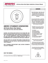
WIRING DIAGRAM
PRODUCT SPECIFICATIONS ARE SUBJECT TO CHANGE WITHOUT NOTICE.
USE INSTALLATION INSTRUCTIONS SUPPLIED WITH PRODUCT.
Jacuzzi Whirlpool Bath has obtained applicable code (standards) listings generally available on a national basis for
products of this type. It is the responsibility of the installer/owner to determine specific local code compliance prior to
installation of the product. Jacuzzi Whirlpool Bath makes no representation or warranty regarding, and will not be
responsible for any code compliance.
JACUZZI WHIRLPOOL BATH
Jacuzzi Whirlpool Bath National Headquarters
P.O. Drawer J, Walnut Creek, CA 94596 (510) 938-7070
Service Support: Call (800) 363-0251
©2000 Jacuzzi Whirlpool Bath S137000 5/00
Printed on Recycled Paper Printed in U.S.A.
WATER VALVE
TANK - FRONT
ELEMENT ELEMENT
TANK - SIDE
BLUE
WHITE
WHITE
STEAM
GENERATOR
TEMPERATURE
SENSOR
(STEAM ROOM)
30 MINUTE TEMP
OR DIGITAL
CONTROL
OPTIONAL
SECOND DIGITAL
CONTROL
K3
K4
TB2
K1 K2
F1 F2
W1
W2
1A FAST-BLOW
J4
SK4
SK3
SK1
JP1
J1
L
H
R
JP2
J5
TB1
12
3
(DIGITAL)
(DIGITAL)
(30 MIN)
OPTIONAL
AUTOMATIC
DRAIN
ON/OFF
L1
L2
100mA SLO-BLOW
BLK/RED
BLK/RED
BLK
BLK
RED
WIRES
ORANGE
WIRES
18
/