Page is loading ...

INSTALLATION INSTRUCTIONS
EASYSTEAM™ STEAMERS
4211-1431 6/12/17 Technical Support: 1-425-951-1120 1-800-363-0251 supp[email protected] Page 1 of 17
AMEREC AK4.5, AK7.5, AK11 and AK14
STEAMBATH GENERATORS
I
nstructions for 208V and 240V 1/3 Phase Models.
(Use 240V models for 400-415V~N3 installations)
FOR USE WITH R30K CONTROLS
SAVE THESE INSTRUCTIONS
READ ALL INSTRUCTIONS CAREFULLY BEFORE INSTALLATION.
POST SAFETY "WARNING" LABEL OUTSIDE STEAMBATH. LABEL
SHOULD BE POSTED ON OR ADJACENT TO DOOR TO STEAM
ROOM IN COMMERCIAL INSTALLATIONS.
SECTION 1: GENERAL INFORMATION
Amerec steam generators are tested by Intertek-ETL Laboratory. The
steam generators come assembled and ready for installation. Check that
the size and rating of the generator is suitable for your application:, refer to
the AK Steam Room Sizing and Rough-in Guide (Amerec doc. 4211-36).
Note: The AK steamer may be configured for single or three phase power during installation
IMPORTANT
An exhaust fan installed outside the steam room is strongly recommended
to remove excess steam from the bathroom or shower area.
R30
STEAM GENERATOR
CAUTION
Electrical grounding is required on all
AMEREC Steam bath Generators.
All electrical supplies should be
disconnected when servicing generator.
All wiring must be installed by a licensed
electrical contractor in accordance with
local and national codes.
All plumbing must be installed by a
licensed plumber in accordance with all
applicable local and national codes.
AK series generators are
for indoor use only.
AK series generators are not for
space heating purposes.
Be certain that steam bath enclosures
are properly sealed to avoid water
damage from escaping steam. It is
recommended that 100% silicone caulk
be used to seal all pipes and fittings.
Steam must be prevented from escaping
into the wall cavity.
Never shut off the water to a
steam generator that is in use.
Electric Shock Hazard - High voltage
exists within this equipment. There
are no user serviceable parts in this
equipment.

INSTALLATION INSTRUCTIONS
EASYSTEAM™ STEAMERS
4211-1431 6/12/17 Technical Support: 1-425-951-1120 1-800-363-0251 sup[email protected] Page 2 of 17
TABLE OF CONTENTS
Section Description Page
Important Safety Instruction 3-5
1 Mounting the Generator 6-7
2 Water Quality Requirements 7
3 Plumbing Instructions 8-12
4 Wiring Instructions 10
5 Bath Control Installation 11
6 Initial Start 11
Electrical Information Charts 13
7 Service 13-14
8 Troubleshooting 14-15
Contact Information 17
Wiring Diagrams 18-19

INSTALLATION INSTRUCTIONS
EASYSTEAM™ STEAMERS
4211-1431 6/12/17 Technical Support: 1-425-951-1120 1-800-363-0251 supp[email protected] Page 3 of 17
WARNING
Thank you for purchasing your new AMEREC AK steam generator.
If we can be of any assistance, please call our Technical Support at 1-800-363-0251 or 1-425-951-1120
FOR THE SAFETY OF YOU AND YOUR FAMILY OR CUSTOMERS, PLEASE READ THE
FOLLOWING WARNINGS AND ALL INSTRUCTIONS BEFORE USING YOUR STEAMBATH.
POST "STEAMBATH INSTRUCTIONS" LABEL OUTSIDE STEAMBATH FOR SAFETY WARNINGS.
SAVE THIS MANUAL
FOR THE SAFETY OF YOU AND YOUR FAMILY OR CUSTOMERS, PLEASE READ THE
FOLLOWING WARNINGS AND ALL INSTRUCTIONS BEFORE USING YOUR STEAMBATH.
POST "STEAMBATH INSTRUCTIONS" LABEL OUTSIDE STEAMBATH FOR SAFETY WARNINGS.
Electric Shock Hazard - High voltage exists within this equipment. Disconnect all electrical power before
servicing the generator. All installation and service to this equipment should be performed by qualified
licensed personnel in accordance with local and national codes. There are no user serviceable parts in
this equipment.
Electrical grounding is required on all AMEREC steambath generators. The generator is designed for hookup with
copper wire only, 75°C or better.
Wire the controls exactly as described. Do not connect any additional wiring or power supplies to the controls or
their terminals in the generator.
Service only by authorized personnel!
All plumbing must be installed by a licensed plumber in accordance with all applicable local and national codes.
Install indoors only. Protect from freezing. Generator must be level side to side and end to end.
The pressure relief valve and generator drain must be installed in such a fashion that the risk of scalding is reduced
to a minimum. Draining these outlets into the steam room may present a scald hazard and may damage materials
used to construct the room.
Danger To reduce the risk of explosions, do not interconnect t steam lines!!
Caution The steam outlet carries hot vapor! A separate steam line is required for each steam outlet.
Do not connect a valve or shut-off in the steam line! Avoid traps and valleys in the steam line where
water could collect and cause a steam blockage. The hot steam line must be insulated against user contact.
Do not install the steam head near a bench or where steam may spray or where condensation will drip on the user
as this will present a scald hazard.
Be certain that steambath enclosures are properly sealed to avoid water damage from escaping steam. It is
recommended that 100% silicone caulk be used to seal all pipes and fittings. Steam must be prevented from
escaping into the wall cavity. Centering the steam pipe is critical in rooms made of plastic, acrylic, resin, fiberglass
or similar materials. Allowing the steam pipe to touch materials not rated 240°F (115°C) or higher will result in
damage to these materials.

INSTALLATION INSTRUCTIONS
EASYSTEAM™ STEAMERS
4211-1431 6/12/17 Technical Support: 1-425-951-1120 1-800-363-0251 supp[email protected] Page 4 of 17
AVERTISSMENT
Merci pour l'achat de votre nouveau AMEREC AK générateur de vapeur.
Si nous pouvons vous être utiles n'hésitez pas à appeler notre assistance technique au 1-800-363-0251.
POUR LE SËCURITË DE VOTRE FAMILLE ER VOUS OU CLIENTS, VEUILLEZ
LIRE LES AVERTISSEMENTS SUIVANTS ET TOUTES LES INSTRUCTIONS AVANT
D'UTILISER VOTRE BAIN DE VAPEUR.
POST "BAIN DE VAPEUR" LABEL HORS D UN BAIN DE d'INSTRUCTIONS
POUR DES AVERTISSEMENTS EN MATIÈRE DE SÉCURITÉ.
ENREISTREZ CE MANUEL
POUR LA SËCURITË DE VOTRE FAMILLE ET VOUS OU VOS CLIENTS, VEUILLEZ LIRE
APRèS AVERTISSEMENTS ET TOUTES LES INSTRUCTIONS AVANT D'UTILISER VOTRE BAIN DE VAPEUR.
POST "BAIN DE VAPEUR" LABEL HORS D' UN BAIN DE VAPEUR D'INSTRUCTIONS POUR DES
AVERTISSEMENTS EN MATIÈRE DE SËCURITË.
Risque de choc électrique - Haute tension existe au sein de ce matériel. Débranchez toute source d'alimentation
avant de procéder à l'entretien du générateur. Toutes les instructions d'installation et service à cet équipement doit
être effectuée par du personnel autorisé qualifié conformément aux codes locaux et nationaux. Il n'y a pas de pièce
réparable par l'utilisateur à cet équipement.
Mise à la terre électrique est requis sur tous les générateurs bain de vapeur AMEREC. Le générateur est conçu pour connecter
un fil de cuivre uniquement, 75 °C ou mieux.
Câbler le contrôle très exactement comme indiqué. Ne connectez aucun câblage supplémentaire ou blocs d'alimentation pour
les commandes ou leurs terminaux dans le générateur.
Service uniquement par le personnel autorisé!
Toute la tuyauterie doit être installé par un plombier sous licence conformément à tous les codes locaux et nationaux
applicables.
Installer à l'intérieur uniquement. Protéger du gel. Générateur doit être mise à niveau latérale et l'extrémité à l'autre.
La valve de limitation de pression et purge du générateur doit être installé de telle façon que le risque de brûlure est réduit à un
minimum. Vidange de ces prises dans la salle de vapeur peut présenter un risque de brûlure et peut endommager les matériaux
utilisés pour construire la salle.
Danger Pour réduire les risques d'explosion, ne pas connecter les conduites de vapeur t!!
Attention La sortie vapeur transporte vapeur chaude ! Une conduite de vapeur distincte est requise pour chaque
sortie vapeur. Ne connectez pas une valve ou l'arrêter dans la conduite de vapeur! Éviter les pièges et les vallées
dans la conduite de vapeur où l'eau pourrait recueillir et provoquer un blocage de vapeur. La vapeur chaude ligne doit être
isolée par rapport au contact de l'utilisateur.
Ne pas installer la tête de vapeur près d'un banc ou où la vapeur peut pulvériser ou où la condensation s'égoutter sur l'utilisateur
comme cela présentera un risque de brûlure.
Etre certain que le bain de vapeur boîtiers sont étanches afin d'éviter les dégâts d'eau de s'échapper la vapeur. Il est
recommandé que 100% mastic au silicone utilisée pour obturer tous les raccords et tuyaux. La vapeur doit être empêché de
s'échapper dans la cavité du mur. Centrage du tube à vapeur est critique dans les chambres faites de plastique, de l'acrylique,
résine, la fibre de verre ou des matériaux similaires. Permettant le tube à vapeur pour toucher les matériaux non coté 115°C ou
plus aura pour effet d'endommager ces matériaux.

INSTALLATION INSTRUCTIONS
EASYSTEAM™ STEAMERS
4211-1431 6/12/17 Technical Support: 1-425-951-1120 1-800-363-0251 sup[email protected] Page 5 of 17
POST "WARNING LABEL OUTSIDE STEAMBATH FOR SAFETY WARNINGS
Étiquette d'avertissement "Extérieur poste baiin de vapeur pour les avertissements relatifs à la sécurité

INSTALLATION INSTRUCTIONS
EASYSTEAM™ STEAMERS
4211-1431 6/12/17 Technical Support: 1-425-951-1120 1-800-363-0251 sup[email protected] Page 6 of 17
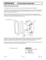
SECTION 1: MOUNTING THE STEAM GENERATOR
DIAGRAM 1 DIAGRAM 2
The AMEREC steam generator can be hung on a wall or sit on its base. The best mounting location will satisfy all or most of the
following:
WARNING: The generator will not operate properly, unless it is mounted level with the arrows pointed up
1. The generator should be installed in a dry, well ventilated area. Suggested locations are under a vanity, in a closet,
attic, crawl space or basement. Do not mount outdoors.
2. If the generator will be in an area difficult to access, the water supply should be equipped with easily access water shut-off
valve in case of emergency.
3. If the steam line is in an area where the temperature will be below 39°F (4°C) best results can be obtained by insulating the
steam pipe. Do Not mount the generator in an area subject to freezing.
4. The generator must be mounted in a minimum 7 cubic feet (0,2 cubic meter) space.
5. The location must allow access for service! Provide clearance for plumbing and electrical service and for element
removal. See Diagram 1.
6. The steam line should slope to allow condensation to drain. The mounting location should minimize the number of bends
and elbows in the steam line
7. The mounting location should allow for a drain hook up.
8. The steam line should be less than 20ft (6 m) long; 3ft (1 m) is preferred. Steam lines over 20ft (6 m) long should be
insulated.
WARNING
There must be no dips or valleys in the steam line.
Install the steam head so as to avoid potential user direct contact with the steam or where condensation may drip on the
user as this may present a scald hazard.
Do Not install any valves or other shut-off devices in the steam line!
Do Not interconnect steam lines! A separate steam line is required for each generator!
Do Not connect the drain line to the steam line or allow the drain empty into the steam room!
Do Not connect the pressure relief valve into the steam line or vent it where someone nearby could be scalded!
Do Not allow the relief valve to vent into the steam room!
Leave 13” [330 mm]
Service Clearance
14.5” [368 mm]
13.2”
[335,3 mm]
0.8”
[20,3 mm]
Steamer must be level
End-to-End and
Front to Back

INSTALLATION INSTRUCTIONS
EASYSTEAM™ STEAMERS
4211-1431 6/12/17 Technical Support: 1-425-951-1120 1-800-363-0251 sup[email protected] Page 7 of 17
SECTION 1: MOUNTING THE STEAM GENERATOR (continued)
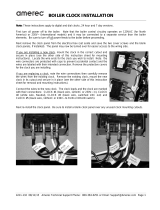
1. WALL MOUNTING: Remove the side cover. Note the location of the
mounting holes on the back of the generator. The screws must set directly into
studs or equivalent supports. Drill pilot holes on 14-1/2” (368 mm) centers and
install the two #10 1½" screws, provided.
See at right.
a) Carefully hang the generator on the two screws. Tighten the screws.
b) The generator may be further secured with two screws mounted on the
same 14-1/2” (368 mm) centers as shown.
c) Replace the front cover with its four screws.
2. FLOOR MOUNTING:
a) In general, the width of the unit allows it to sit on a shelf, across the ceiling
joists or on a floor. The generator must be restrained from moving.
Normally, the piping will provide adequate support. If not, additional
support must be provided.
b) All floor installed generators must provide for routine draining of the tank
and for draining the safety valve’s outlet.
SECTION 2: WATER QUALITY REQUIREMENTS
The nature of a boiler or steam bath generator requires testing of the feedwater
to avoid potential high concentrations of impurities which can cause a deposit
or scale to form on the internal surfaces. This deposit or scale can interfere with
the equipment's proper operation and even cause premature boiler or generator
failure. Concentration of impurities is generally controlled by treating the
feedwater and or "blowing down" the generator or boiler when it is not heating.
The "blow down" process
involves removing a portion of the tank water with high solid concentration and
replacing it with makeup water.
This is particularly important in areas with high calcium levels and other water
quality problems. Calcium build-up can cause poor steamer performance and damage the heating elements!
Be especially careful to prevent foaming in the steamer’s water! Foaming water will affect the water level measuring
systems in steamers and boilers, causing operation problems and possibly leading to early element failures!
To insure proper operation, the water supply should be tested prior to operating the equipment. There are several treatment
processes which can be used if you have a problem with hard water. A local reliable water treatment company can recommend
the appropriate treatment if required. The recommended feedwater quality is listed on the next page.
Recommended Feedwater Quality
Hardness 10 – 30 ppm - (0.5 - 1.75 gpg)
T-Alkalinity 150 – 700 ppm - (8.75 - 40.8 gpg)
Silica Range 15 – 25 ppm - (1.28 - 1.45 gpg)
PH (strength of alkalinity) 10.5 -- 11.5
IMPORTANT!
Regular maintenance will help your steamer work properly for a long time. Check for leaks,
loose or damaged wires, signs of corrosion and calcium build up in the tank on the level probe.
WALL MOUNTING
14.5” [368 mm]
14.5” [368 mm]

INSTALLATION INSTRUCTIONS
EASYSTEAM™ STEAMERS
4211-1431 6/12/17 Technical Support: 1-425-951-1120 1-800-363-0251 sup[email protected] Page 8 of 17
SECTION 3: PLUMBING INSTRUCTIONS
All plumbing shall be installed by a licensed plumber and conform with local & national codes.
Materials Needed:
3/8NPT, 1/2NPT and 3/4NPT unions: recommended to allow easy disconnect of steamer for servicing
3/8" copper pipe and 3/8” male NPT adapter for the water supply to the generator.
3/8" water supply shut-off valve.
3/8" supply valve housing and filter (optional depending on local water conditions).
1/2" copper pipe and (2) 1/2" male NPT adapters for the steam line between the generator and the steam room outlet.
3/4" copper pipe and 3/4" male NPT adapter for the tank drain.
3/4" copper pipe, fittings, and a union for the Pressure Relief Safety Valve drain.
Tube 100% silicone caulk.
Pipe compound suitable for drinking water use at more than 212°F (100°C).
1. INSTALL WATER LINE Connect a cold water line to the generators water valve. The valve input is 3/8” NPT. A shut-off valve
should be placed in the line for each generator to allow easier servicing later, if needed, and for emergency shut-off. Make sure
the shut-off is open, providing water to the generator before first turning the on.
IMPORTANT
Water pressure required: 20-100 psi (138-690 kPa)
If the generator is mounted in a place difficult for the home owner to access, the water supply
shut-off valve should be located where it can be quickly accessed in an emergency.
Do not use a saddle valve or saddle fitting for the water shut-off valve.
Flush water supply line before final hookup.
2. INSTALL STEAM LINE
a) At the generator: Install a 1/2" male NPT sweat adapter directly into the tank. Install a 1/2" union in the steam line to allow
easy disconnection for later servicing. Note: There must be no valves, shut offs or restrictions in the steam line!
Diagram 3a
Diagram 3b

INSTALLATION INSTRUCTIONS
EASYSTEAM™ STEAMERS
4211-1431 6/12/17 Technical Support: 1-425-951-1120 1-800-363-0251 sup[email protected] Page 9 of 17
SECTION 3: PLUMBING INSTRUCTIONS (continued)
b) Run the 1/2" copper steam line from the generator to the steam room. Refer to SECTION 1: MOUNTING THE STEAM
GENERATOR and Diagrams 3a and 3b.
The steam line must slope to allow condensation to drain into the tank or room.
There must be no dips in the steam line. Low areas may collect condensation and cause faulty operation or cause hot
water to spit into the room.
c) The steam line should enter the steam room 18” (460 mm) above the floor or at least 12” (305 mm) above a tub rim or
ledge. The steam line outlet should be at least 6” (150 mm) from other steam heads to either side and 12” (305 mm) from
walls or other surfaces to either side. See Diagrams 4, 5 and 6.
Note: See Diagram 6 for a typical installation. Additional steam heads may be
added to any installation to reduce steam noise or to provide more steam
dispersion around a large room
Note: if steam vents are too close to other surfaces, the steam may be cooled
and the surfaces damaged.
d) At the steam room: Drill/prepare a 1-3/8” (35 mm) hole for the steam line
entry. Center the 1/2" copper steam pipe in the hole. See Diagram 4.
Terminate the steam line with a 1/2" NPT male adapter.
Stub the line out into the room 3/8” (9,5 mm) from the finished surface.
Secure the steam line to a structural member.
3. INSTALL STEAM HEAD INSULATOR: Fill in gap (using 100% Silicone
caulk between steam pipe and finished wall surface at point of entry (see
Diagram 4). Apply silicone caulk to the finished wall side of the steam head
insulator (see Diagram 5) and screw on hand tight until it is flush with the wall
with the opening pointing down. If a hand tight fit does not align with the
opening pointing down, use Teflon tape on the steam line threads to adjust fit.
4. INSTALL STEAM HEAD: Slide the steam head on until it rests firmly against
the finished wall. Tighten the hex head screw underneath the steam head to
secure it in place with the Allen wrench provided. The steam head should be
level with its fragrance reservoir at the top. See Diagrams 4 and 6.
IMPORTANT
All fixture holes must be sealed with 100% silicon caulk to avoid moisture
damage within walls. Check all of the standard fixtures in the steam room.
DIAGRAM 6
DIAGRAM 4
DIAGRAM 5
12” [305 mm]
minimum
6”
[150 mm]
minimum
18”
[460 mm]
minimum
Shown with optional 2
n
d
steam outlet.
3/8”
(9,5 mm)
FROM
WALL
1/2 NPT
1-3/8”
(35 mm)
HOLE
SILICONE
BACK
SIDE

INSTALLATION INSTRUCTIONS
EASYSTEAM™ STEAMERS
4211-1431 6/12/17 Technical Support: 1-425-951-1120 1-800-363-0251 sup[email protected] Page 10 of 17
SECTION 3: PLUMBING INSTRUCTIONS (continued)
5. INSTALL PRESSURE RELIEF SAFETY VALVE: Install the pressure relief valve into its port on the generator. Install the
safety valve within 6” (150) mm of the generator. Run a 3/4" copper line from the valve to a gravity flow drain. The pressure relief
valve outlet must drain in accordance with local and national codes.
AUTODRAIN All generators must have a drain valve installed to allow draining the tank for cleaning and maintenance. A
manual ball valve is supplied. An electronic ball valve is available in the ADK Autodrain option. When installed, Autodrain
automatically rinses and empties the steam tank approximately 25 minutes after a steam bath stops. This cleans the tank to
reduce problems caused by poor water quality and ensures every steam bath starts with clean, fresh water. Contact Amerec
Technical Support for more information. [email protected] or 1-425-951-1120 or at 1-800-363-0251
INSTALL DRAIN VALVE: Install 3/4" NPT pipe nipple directly into the
tank as shown in Diagram 7. Install a 3/4" ball valve or an Autodrain on
the nipple then add another nipple to the outlet of the valve. Add a union
to the outlet nipple to allow easy disconnection during servicing. Run a
3/4" copper line from the union to a gravity flow drain. The drain must be
connected in accordance with local and national codes.
IMPORTANT
All drain lines must run downhill, away from the steam generator! Also
see Diagram 3
Do not run the drain uphill.
Do not drain the safety valve into the steam line!
Do not drain the safety valve into the steam room! Draining the
tank into the steam room may present a scald hazard or
damage the materials used to construct the steam room.
Do not drain into the steam room!
SECTION 4: WIRING INSTRUCTIONS
ALSO SEE ELECTRICAL INFORMATION CHART AND WIRING DIAGRAMS
1. ELECTRICAL ROUGH-IN: Size wire for the generator as required by local or national codes. See the electrical information
on page13 for further information. Use copper wire only. Leave 4 ft (1,2 m) of slack wire at generator location for finish hookup.
Connect the generator to a dedicated circuit breaker. A GFI device is usually not required by safety agencies. One may be
installed if required by local codes or the owner. A GFI device will tend to nuisance trip due to heater element aging.
a. Route the copper supply wire with appropriate strain relief through the hole marked POWER ENTRY.
b. Connect the supply wires to the power terminal block as indicated on the wire diagram for your voltage and phase. This
may require moving factory installed jumper. Do not change the steamer’s internal jumpers or wiring. Only the supply wiring
side of the terminal blocks require configuration by the installer.
c. Connect the Earth wire to the copper Earth ground lug.
d. Cover the supply wires inside the steamer with a protective mesh or similar material to protect them from water valve
heating.
2. ELECTRICAL INFORMATION The AK steamers are available in 2 basic versions, one for 208V (intended for 208VAC
single and three phase for North American use) and the other for 240V (intended for all other installations. The 240V
models are rated at 240VAC but may be used on 208 to 240V single phase Line-to-Line or 208 to 240V~N (Line-to-Neutral)
or 208V to 240V three phase Delta without Neutral or for Y-connected three phase 380 to 415V~N3.
All Units are factory wired for single phase installation. The installer may change the input to three phase or three phase
with Neutral during initial installation (see the wiring diagrams on page 19-20).
The National Electrical Code (NEC) limits a steamer’s current to 48 Amps so, two separate power supplies ciruits are
required for the AK11 208V single phase.
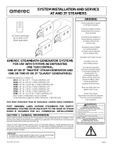
See page 17 for Mains Wiring Details: Note: jumpers shown are supplied with the steamer
DIAGRAM 7
HEATING ELEMENT
A
CC
E
SS
MANUAL VALVE
AUTODRAIN
VALVE
4” (100 mm)
3/4” PIPE
OR
Diagrams 7 and 8 show the optional Autodrain valve

INSTALLATION INSTRUCTIONS
EASYSTEAM™ STEAMERS
4211-1431 6/12/17 Technical Support: 1-425-951-1120 1-800-363-0251 sup[email protected] Page 11 of 17
SECTION 5: R30K BATH CONTROL
The R30K low voltage control can be mounted directly to a finished wall either inside or outside the steam room. The R30K does
not control the temperature in the steam room.
Use a 1-1/2” (36 mm) hole saw to drill a hole in the finished steam room wall where
the control is to be mounted (the control cable should already be roughed-in to this
location). See Diagram 13
Locate the control cable, pull it out through the mounting hole and plug it into the
connector on the back of the control board,, inside the housing.
Run a bead of 100% silicone caulk around the perimeter on the back of the control
housing. See Diagram 12. Insert the control into the wall cavity. See Diagram 13.
Connect the R30K control's cable to the steamer and plug it in to the S30B jack (top edge of the circuit board next to the S30A
terminal block).
DIAGRAM 13
SECTION 6: INITIAL START
1. Assure power and water are on. Press the control’s ON/OFF switch. The control should light then the water valve should turn
on to fill the steamer. While filling, check for leaks.
2. After the tank has filled to a safe level, the heating elements will turn on. Allow about 10 minutes for the steam to appear in
the steam room.
3. Once the steam is visible, use the control to turn the bath off. The steam should stop within a couple minutes and the water
valve should turn off. The control should not be lit.
4. Press the ON/OFF switch again. The control should light.
5. Within one minute the unit should again produce steam. It should call for water once every two minutes or more depending on
its power rating. It’s normal for the flow of steam out the steam head to slow for up to 10 seconds each time the unit calls for
water.
6. The steam bath will halt automatically in 30 minutes. When the time runs out the steam will stop and there should not be any
water flow. The control should not be lit.
DIAGRAM 12
R30K
1-1/2” (36 mm)
HOLE
SILICONE

INSTALLATION INSTRUCTIONS
EASYSTEAM™ STEAMERS
4211-1431 6/12/17 Technical Support: 1-425-951-1120 1-800-363-0251 sup[email protected] Page 12 of 17
Electrical Information:
Nominal Room Size cu ft Room Size cu m
Model VAC min
Max
min
Max
AK4.5
208
60 90 1.7 2.5
240
AK7.5
208
80 200 2.3 5.7
240
AK11
208
175 375 5.0 10.6
240
Nominal Watts at operating VAC
Model VAC 208
230
240 400 415
AK4.5
208 4507
240 3380 4133 4500 4133 4500
AK7.5
208 7511
240 5633 6888 7500 6888 7500
AK11
208 11267
240 8262 10102 11000 10102 11000
Nominal Amps 1 phz Recommended Breaker
Model VAC 208
230
240 208 230
240
AK4.5
208 22
30
240 16 18 19 20 30 30
AK7.5
208 36
50
240 27 30 31 40 40 40
AK11
208 18 & 36
30 & 50
240 40 44 46 50 60 60
Nominal Amps at operating VAC, 3 phz Recommended Breaker
Model VAC 208
230
240
400 415
208
230 240 400 415
AK4.5
208 14
20
240 9 10.0 10.9 6.0 6.3 15 15 15 15 15
AK7.5
208 21
30
240 16 17.3 18.1 10.0 10.5 20 30 30 15 15
AK11
208 31
40
240 23 25.4 26.6 14.6 15.4 30 40 40 20 20
Notes:
* Use only copper wire rated 600V~ and
75°C minimum
* All models require Earth ground
* All line voltage must be more than 195V~
while the steamer is heating
* Steamers must be connected to a means
for disconnecting all supply voltages
* All 208V AK11 single phase require two
Mains supplies

INSTALLATION INSTRUCTIONS
EASYSTEAM™ STEAMERS
4211-1431 6/12/17 Technical Support: 1-425-951-1120 1-800-363-0251 sup[email protected] Page 13 of 17
SECTION 7. SERVICE
1. DESCRIPTION OF STEAM GENERATOR
The Printed Circuit Assembly (the “PCA”) provides the basic functions necessary to produce steam. The PCA controls makeup
water, provides a water level permissive for powering the elements and provides raw DC power for the system.
The PCA also provides regulated non-interruptible 12 VDC power for the generator control, and 5 VDC for the control, and a
built in bath timer.
2. MAINTENANCE OF STEAM GENERATORS
VISUAL INSPECTION - Whenever the generator is opened, inspect for any evidence of water leaks. Inspect the wiring for
any evidence of overheating. Check all electrical connections for tightness.
FLUSH TANK - Flush monthly, or more often, depending usage and on local water conditions.
FLUSHING PROCEDURE: with manual drain
1. The generator should be cool.
2. Press the ON/OFF button to turn the steamer on. The control should light.
3. Open the manual drain valve.
4. The unit will drain. Allow the water to run for a full 10 minutes, then press the ON/OFF button.
5. Allow the unit to drain completely. When the water stops, close the drain valve.
FLUSHING PROCEDURE: with Autodrain
1. The generator should be cool.
2. Press the ON/OFF button to turn the steamer on. The control should light.
3. Open the manual drain valve (if installed) and manually open the Autodrain valve by moving its lever until it latches.
4. The unit will drain without heating the water. Allow the water to run for a full 10 minutes, then press the ON/OFF button.
The control light should turn off.
5. Allow the unit to drain completely. When the water stops, close the drain valves.
3. REPAIR OF GENERATORS
A. ELEMENT REPLACEMENT:
Disconnect power from the unit. Drain the tank. Remove the front and HEATING ELEMENT ACCESS covers. Note the wire
connections. (See diagram) Remove the element wires. Using a hot water element socket, remove the element. To install a new
element, mount a new element gasket on the element. Clean the element port and add a light coat of Rectorseal No. 5 pipe
thread compound to the threads. Insert and hand tighten the element-gasket combination. Notice the element end orientation as
shown in diagram. Tighten the element until the orientation is the same as diagram, ± 15°. The gasket should be set and tight
but not deformed to a rounded or bulbous appearance. If the drain valve was removed reinstall it. Reconnect the wiring. Test the
unit per SECTION 7: INITIAL TEST. Check for leaks at the element. Replace the front and HEATING ELEMENT ACCESS
covers. (Replace with factory supplied elements only)
IMPORTANT
The blue wire connected to MAX on the PCA must be connected to
the shortest of the three level probes, the black wire (MID)
to the long probe with black tubing and the white wire (MIN) connected to the longest probe with white tubing.
B. PRINTED CIRCUIT REPLACEMENT:
Printed circuit assembly (PCA) removal and replacement must be performed in the following sequence: any other method can
damage the PCA.
IMPORTANT
The PCA’s contain static sensitive devices. Static electricity may damage PCA’s. Handle accordingly.
Disconnect power from the unit. Note and tag the positions of all wires that plug into the printed circuit. Remove all the wires
from the relays. When removing these wires, pull on the connector, not the wire. Disconnect all three wires from the water level
probe. Note: the blue wire is connected to the shortest of the triple pronged water level probe. Disconnect control cable.Remove
the PCA mounting screws. To install the board, reverse this procedure. The wire lugs must fir tightly onto the relay tabs! Test
the unit per SECTION 7: INITIAL TEST.
C. WATER SOLENOID REPLACEMENT:
Disconnect power from the unit. Turn the water supply OFF. Disconnect the water supply from the water solenoid valve.
Remove the front cover. Remove the two blue wires from the water solenoid valve. Rotate the self-tightening hose clamp so it
can be loosened with a pair of pliers. Squeeze the clamp and move it down towards the shelf and off the valve outlet tube.
Remove the two 1/4" - 20 hex head bolts and lock washers that attach the valve to the chassis. Pull the valve off the rubber fill
hose. To install the valve, reverse these instructions. Test the unit per SECTION 7: INITIAL TEST.

INSTALLATION INSTRUCTIONS
EASYSTEAM™ STEAMERS
4211-1431 6/12/17 Technical Support: 1-425-951-1120 1-800-363-0251 sup[email protected] Page 14 of 17
SECTION 7. SERVICE (continued)
D. LEVEL PROBE REPLACEMENT:
Disconnect power from the unit. Remove the front cover. Note where the blue wire is connected to the triple pronged water level
probe. Disconnect all three wires from the water level probe. Using a 1-1/4" box wrench, remove the level probe. Install a new
level probe. Use Teflon Tape on threads of probe if required. Tighten until the bottom of the plastic nut is 1/8" to 3/8" (3,2 to 9,5
mm) above the top of the port. See diagram 11. Reattach the three wires. Test the unit per SECTION 8: OPERATIONAL
TEST.
IMPORTANT
The blue wire connected to “L” on the PCA must be connected to the shortest of the three level probes, the black wire to the
probe with black tubing and the white wire to the probe with white tubing.
IMPORTANT The level probe may be extremely tight. Damage to the insulation or chassis may result unless the tank is
properly blocked or supported during probe removal or installation. It may be necessary to completely disconnect and
disassemble the generator.
SECTION 8. TROUBLESHOOTING
There are no user serviceable parts in the Generator. All repair should be performed by a qualified service person. For
additional assistance or the factory authorized service person nearest you, call Amerec Technical Support at 1-425-951-1163 or
1-800-363-0251. The followiong Trouble Shooting Guide is intended as a general aid only. Follow ACTION TO BE TAKEN in
order until the problem is resolved. Where replacements or repairs are indicated, see the appropriate paragraph of SECTION 8:
SERVICE.

INSTALLATION INSTRUCTIONS
EASYSTEAM™ STEAMERS
4211-1431 6/12/17 Technical Support: 1-425-951-1120 1-800-363-0251 sup[email protected] Page 15 of 17
SYMPTOMS PROBABLE CAUSES ACTION TO BE TAKEN
Control won't turn
ON
(Control light off)
Improper or no power
supplied
or
Control improperly
connected
or
Circuit board (PCA)
faulty
or
Control cable faulty
or
Control faulty
1.a. Make sure circuit breaker is on and 208/240VAC is supplied.
b. Use voltmeter to check the line voltage across the two fuses on the PCA.
Voltage should be 208 to 240VAC.
c. Check the PCA fuses. If a fuse is open, replace with the same size and type: F1
is a 100mA Slo-Blo (Time Delay) fuse, F2 is 1A Fast-Blo (non-Time Delay) fuse.
If the fuse fails again, contact Support.
2. Turn off all power to the steamer.
a. Check that the control is properly installed. See section 5.
b. Check the control cable for installation damage (nail or staple holes, damaged
connectors, etc. Contact Support.
c. Replace the control. Contact Support.
d. Replace the PCA. Contact Support.
Control OFF
(control light off)
Water runs out
the steam head
and won't shut off.
Water solenoid valve
is stuck open
or
PCA is faulty
1. Turn off power to the steamer. If water stops, go to step 2.
a. Disconnect the two blue wires from the water valve. Turn the power back on. If
the water stops, the PCA may be faulty. Contact Support for assistance.
b. If the water continues to run, go to step 2.
2. (with the power off) Shut off water to the steamer and remove the water valve.
Carefully disassemble the valve, clean it, reassemble and reinstall it then retest. If
water continues to run, contact Support.
Control ON
(control light lit)
Water runs out
the steam head
and won't shut off.
Connections between
the PCA
and the water level
probe faulty
or
PCA faulty
1. Check that the two white wires (marked H and R) are connected to the two tallest
level probe rods and the blue wire (marked L) is connected to the shortest rod.
2. The PCA may be faulty. Contact Support.
Control ON
(control light lit)
Tank empty, unit
won't fill.
Water supply off
or
Water valve faulty
or
Level probe faulty
or
or PCA faulty
1. Make sure water is supplied to the steamer and all valves are open.
2. Does the water valve solenoid make noise (hum)?
a. Yes - water valve may be plugged. Clean and retest.
b. No - go to step 3.
3. The PCA may be faulty. Contact Support.
Control ON
(control light lit
and not blinking)
Unit won't steam.
Unit has not filled
completely
or
Heating elements
burnt out
or
Level probe faulty
or
PCA faulty
1. a. Push the control OFF.
b. Open the drain valve and allow the tank to drain completely.
c. Close the drain valve.
d. Push the control ON.
e. Unit will begin filling: listen for a click noise. Within 20 seconds after click noise
is heard, the water fill should shut off, indicating the tank is full. If the tank does
not fill, go to section: SYMPTOMS "Unit won't fill".
2. If the tank filled but the relay click was not heard, temporarily ground the two long
probes. If the click is heard as each probe is grounded, clean or replace the level
probe. If the click is not heard replace the PCA. Contact Support for assistance.
3. If the tank filled and the relay click was heard, remove the heating element access
panel. Use a voltmeter to verify line voltage between the two wires on each
heating element. If proper voltage is found the element(s) may be faulty. If no
voltage is found check for proper wiring (refer to the wiring diagram). Contact
Support.
Control ON
Control light is
blinking
Control connection
error
or
Control cable faulty
or
PCA is faulty
Check control is connected to the S30 jack on the PCA
Contact Support for assistance.

INSTALLATION INSTRUCTIONS
EASYSTEAM™ STEAMERS
4211-1431 6/12/17 Technical Support: 1-425-951-1120 1-800-363-0251 sup[email protected] Page 16 of 17
12
3
4
5
67891
240V L1
(230V~)
240V L2
(NEUTRAL)
SHOWN WIRED FOR
240V STEAMERS
1 phz UP TO AK11
&
208V STEAMERS
1 phzAK4.5 &AK7.5
RED
BLU
ORN
ORN
ORN
RED
RED
BLU
AME REC 20 17
K5
K4
K2
BLUE
WHITE
BLACK
SVC
S30B S30A
S60B
S60A
G1
G2
LD1
LD2
LD3
LD5
AK IN
LD4
DRAIN
WAT E R
W_C
COMMON
LD1 = VNR ON
LD2 = HEAT I N G O K
LD1 = VNR ON
LD3 =WATER ON
LD4 = EXTTIMER
LD5 = BAT H O N
LEDs
Customer
Supplied
Wiring
D
R
A
I
N
V
A
L
V
E
R30K
SERVICE PINS
JUMP FOR ON/OFF
(MOMENTARY )
WATER
(OPTIONAL) AUTODRAIN
S30B
ON/OFF CONTROL
R30K
RED
BLACK
BLUE
COPPER TERMINAL
BLOCK JUMPERS,
FACTORY PROVIDED
BLU
For assistance, contact
P.O. Box 2258, Woodinville, WA 98072
Phone 1-800-363-0251
1-425-951-1120
Fax 1-425-951-1130
eMail [email protected]

INSTALLATION INSTRUCTIONS
EASYSTEAM™ STEAMERS
4211-1431 6/12/17 Technical Support: 1-425-951-1120 1-800-363-0251 sup[email protected] Page 17 of 17
12
3
4
5
67891
208V 1 phz
AK4.5, AK7.5
208V 1 phz
AK11,AK14 2-Circuit
12
3
4567891
208V 3 phz
AK4.5 - AK14
12
3
4
5
67891
L1 L2 L3
Model
AK4.5
AK7.5
AK11
AK14
Model
AK4.5
AK7.5
AK11
AK14
Model
AK4.5
AK7.5
AK11
AK14
208V
4507
7511
11267
13576
WATTS
208V
22
36
18 & 36
24 & 42
208V
14
21
31
38
AMPS 3 PhZ
AMPS 3 PhZ
Notes:
(1) Use only copper wire rated 75°C or better
(2)
See Note (2)
See Note (2)
AK STEAMER FIELD WIRING
See Note (2)
i
AK11 and AK14 single phase require two feed circuits.
Circuit 1 drives one element and the controls and is the lower amperage circuit.
Circuit 2 drives two elements and is the higher amperage circuit.
208V L1
208V L2
CIRCUIT 2
CIRCUIT 1
20V L1 208V L2 208V L1 208V L2
12
3
4567891
240V L1
240V L2
230V~
NEUTRAL
208/230/240V 1 phz
AK4.5, AK7.5, AK11
For 230/240V~N
CONNECT NEUTRAL TO L2
208/230/240V 1 phz
AK14 2-Circuit
See Note (2)
12
3
4567891
CIRCUIT 2
CIRCUIT 1
208/240V 3 phz
AK4.5 - AK14
12
3
4567891
L1 L2 L3
400-415V~ 3N
AK4.5 - AK14
12
3
4
5
67891
L2L1 NEUTRAL L3
Model
AK4.5
AK7.5
AK11
AK14
Model
AK4.5
AK7.5
AK11
AK14
Model
AK4.5
AK7.5
AK11
AK14
208V
3380
6888
8262
10516
230/400V
4133
6888
10102
12858
240/415V
WATTS
208V
16
27
40
18 & 33
230V
18
30
44
20 & 36
240V
19
31
46
21 & 38
AMPS 1 Phase
208V
9
16
23
29
240V
11
18
26
34
400V~N3
6
10
15
19
415V~N3
6
11
15
20
AMPS 3 Phase (V~ 3N)
4500
7500
11000
14000
Notes:
(1) Use only copper wire rated 75°C or better
(2)
See Note (2)
i
240V L1 240V L2
230V~ NEUTRAL
240V L1 240V L2
230V~ NEUTRAL
AK14 single phase require two feed circuits.
Circuit 1 drives one element and the controls and is the lower amp circuit.
Circuit 2 drives two elements and is the higher amp circuit.
208V Models
240V Models
/