Page is loading ...

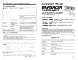
Connecting Diagram
Power
Input
N.C.
COM.
N.O.
-
+
-
+
12VDC
24VDC
Specifications
Bond Sensor Output
Trigger
Relocking Timer
The door will lock automatically after the
circuit trigger connects to each other. VR
timer adjustable up to 80 seconds.
Bond Sensor Output
Power
Supply
N.C. Contact of Control
Device / Access Relay
Timer Adjustment
Shorten
Voltage Selection Jumpers
Check jumper settings before
connecting the lock to input power.
Incorrect jumper settings may cause
or result in damage of the lock.
Lock & unlock status
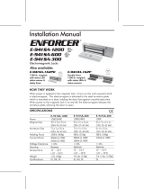
Installation Diagram
Indoor PH Series with Handle
PH-500MTD
-10~55°C(14~131°F)
1A/24VDC
250mA/24VDC
12/24VDC
500mA/12VDC
600 lbs (272Kg)
Blind Nut Assembly
Operating Voltage
Current Draw
(at temperature 20ºC)
Operating Temperature
Electromagnetic Lock Installation Instructions
Zinc plated
Holding Force
Lock Surface Temperature
≦ ambient temperature ±20˚C
Special Finishes for
magnet and armature
plate
I
n
s
w
i
n
g
Copyright © All Rights Reserved. P-MU-PH500MTD Published: 2017.10.13
Armature Assembly Magnet Assembly
Armature Plate
Tamper Screw
Rubber Washer
Electromagnet
Blind Nut
LED Indicator
Green: Unlocked
Red: Locked
Upper Cover
Handle
Trimming plate
Hex screw
Bottom Cover
Note: If the armature plate is not aligned to the magnet or the
reed within the magnet assembly does not sense the small
magnet in the handle, remove the indicated washer to
ensure normal operation.
Blind Nut
Installation Tool Kit

Installation Template
Installation Instructions:
Close the door and make sure the door and door frame are at the
same level of height. Add additional plate spacers if needed.
Allen Wrench
Drill a 3/8" (9.4mm) hole
and hammer the blind nut
assembly into the hole.
Use a wrench or vice-grip to
tightly hold the nut. Then use
the Allen wrench to slowly
tighten the screw until it does
not turn any further.
This compresses the blind nut
so that it remains permanently
fixed in the hole. Remove the
installation tool from the blind nut.
1/2” (12mm) CABLE HOLE
3/8” (9.4mm) BLIND NUTS
MAGNET ASSEMBLY
3/8” (9.4mm) BLIND NUTS
ARMATURE ASSEMBLY
Door
Frame
Important Notes
The electromagnetic lock is fail-
safe and will require a power supply
unit equipped with battery back up for
fear that power failure may increase
security risks.
Do not install a diode or MOV in
parallel with any magnetic lock. A
diode will cause a delay when
releasing the door.
Apply a light coat of a silicon
Iubricant to prevent the maglock
from rusting. Wipe off the excess.
Do not strand power wires and signal
wires in the same cable or conduit.
Trouble Shooting
Problem
Door does not lock
No power
Reduced holding froce
Poor contact between electromagnet and
armature plate
Low voltage or incorrect voltage setting
Sensor output is not functioning
A secondary diode was installed across
the electromagnet
Misalignment between the armature plate
and its magnet
Possible Cause
Solution
Make sure the wires are securely tightened to the correct terminal block
Check that the power supply unit is connected and operating properly
Make sure the lock switch is wired correctly
Make sure the surface of the armature plate is in good shape
Make sure the rubber washer is inserted behind the armature plate
Make sure the contact surfaces of the electromagnet and armature plate are clean
and free from dust
Check the setting of power input volume
Check the settings of the voltage / current volume on the terminals of the maglock
Remove any diode installed across the magnet for “spike”
suppression. (The magnet is fitted with a metal oxide varistor to prevent back EMF)
Check the faces of armature plate and the maglock are aligned face-to-face
Place the template in the proper position on the door and frame.
Drill holes for cable access and blind nuts according to the template.
Install blind nuts and secure the magnet assembly.
Wire the magnet assembly.
Secure the armature plate assembly. After applying power, close
the door and test the holding force. Add rubber washers if there
is still a gap between the armature plate and magnet.
Power
Input
Power
N.O.
COM.
N.C.
Power
Input
SPDT relay
3A/12VDC
F
Wrench
Copyright © All Rights Reserved. P-MU-PH500MTD Published: 2017.10.13
2
1
3
4
5
6
Blind Nut Installation
/