Gianni Industries EM-NH300 Installation guide

Type
Installation guide

This manual is also suitable for

Outdoor
Fold the mounting template 90°
Place the template to the proper
position of the door and frame. Mark
the hole positions of the template on
the door and frame.
Drill the holes according to the marks.
4
Please install the armature plate
as illustrated here. (Dimensions
of the holes are depending on the
door types as illustrated below.)
Armature Plate
Recommendation:
For Micro EM-locks (300 LBS), maximum thickness of door is 44 mm.
For Mini EM-locks (600 LBS), maximum thickness of door is 50 mm.
For Midi EM-locks (800 LBS), maximum thickness of door is 48 mm.
For Maxi EM-locks (1200 LBS), maximum thickness of door is 46 mm.
Drill a Ø8mm hole thrugh
d o o r o n c l o s i n g s id e
enlarge to Ø 12.7mm, by a
sexnut bolt on the opening
side. The depth is 36mm.
12.7mm 8mm
Hollow Metal Door
6.8mm for M8-1.25 thread
Reinforced Door
12.7mm 8mm
Solid Door
36mm
Outdoor
Outdoor
Outdoor
Drill a
and tap on closing side
a M8x12.5 thread.
Ø6.8mm hole
Drill a
d o o r, o n c l os in g s i de
enlarge to Ø12.7mm by a
sexnut bolt on the opening
side.
Ø8mm hole through
Th e ru bb er w ash er m ak es t he
s ur fa ce o f t he a rm at ur e p la t e
adjustable in order to completely fit
the surface of magnetic lock.
Fasten the mounting plate with the
mounting screws. The position of the
mounting plate should be adjustable.
Fix the mounting plate on the door
with mounting screws
Use the Allen wrench and fixing bolts
to tighten the electromagnetic lock to
mounting plate.
Connect the power and test the
holding force. Add washers if there is
gap between the maglock and the
armature plate and then tap the
screw holes.
Copyright © Gianni Industries, Inc. All rights reserved.
P-MU-EM-NH Ver. A Published on: 2012.09.17
1.Pass the power cable through
the mounting plate and the hole of
the maglock.
2.Place the mounting plate above
the maglock. Leave a length of 1
cm from either end of the maglock.
3.Slide the mounting plate into the
maglocks. Fit the maglock from the
bottom to the mounting plate.
4.Use the Allen wrench and fixing
screws to tighten the mounting
plate and maglock.
Outdoor
Outdoor
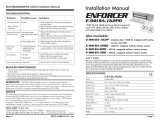
LZ bracket for Inswing doors
Use the fixing bolt to tighten the
electromagnetic lock on L bracket.
Assemble the Z bracket, and make
sure that the position of the Z bracket
is adjustable.
Fasten the armature plate to the Z
bracket (Must add rubber washer)
After the maglock attracts the
arma tur e plat e, adj ust th e Z
bracket to fit the door.
Fasten the Z bracket to the door.
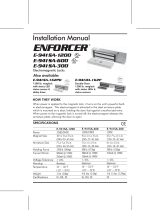
Door Status Sensor (dry contact output) indicates the door
is in an open or closed status.
Reed switch rated 0.2A/12VDC
Ensures the automatic lock mode after the door is closed
properly and it can be adjusted from 1 to 80 seconds. (Timer
Adjustment)
Ti m er A d ju s tm e n t
Bond sensor output (Optional)
Indicates the locked and unlocked status
N.C. contact output: open status
N.O. contact output: locked status
Buzzer Alarm
Door Held Open Alarm is an auditory feedback for users.
Alarm sounds when the door is not closed for over a specified
time limit. VR timer (Timer Adjustment) is adjustable from 1 to
20 seconds.
Make sure the wires are connected properly
Check that the power supply is connected and works properly
Make sure the lock switch is wired correctly
Make sure if the armature plate is deformed
Make sure if the rubber washer was used between the bracket and armature plate
Make sure the contact surfaces of the electromagnet and armature plate are clean
and free from dust and foreign material
Check the electromagnet lock is set for the correct voltage.
Check the voltage at the electromagnetic locks input. if low, determine if the
correct wire gauge is being used to prevent excessive voltage drop.
Remove any diode installed across the magnet for spike
suppression. (The magnet is fitted with a metal oxide varistor to prevent back EMF)
Make sure the armature plate and electromagnetic lock are aligned correctly
Low voltage or incorrect voltage setting
A secondary diode was installed across the
electromagnetic lock
Misalignment between the armature plate and
electromagnetic lock
Poor contact between electromagnet and
armature plate
No power
LED indicator
GREEN: Unlocked
RED: Locked
No LED: No power
Copyright © Gianni Industries, Inc. All rights reserved.
P-MU-EM-NH Ver. A Published on: 2012.09.17
EM-NH350M and EM-NH2350M feature bond sensor output,EM-NH350ML and EM-NH2350ML come with bond sensor output and
an LED indicator.
  • Page 1 1
  • Page 2 2

Gianni Industries EM-NH300 Installation guide

Type
Installation guide
This manual is also suitable for

Ask a question and I''ll find the answer in the document

Finding information in a document is now easier with AI