
2 Specications
MAGLIFE LOCK
USER’S GUIDE
ELECTROMAGNETIC LOCK
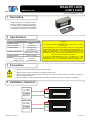
1 Description
The Electromagnetic Lock (Maglife) series is
a surface mounted magnetic lock assembly.
The 80 lbs. Maglock (10MAGLIFELOCK9) is
a small prole model designed for installation
on most types of cabinet doors and drawers.
DESCRIPTION 10MAGLIFELOCK9
HOLDING FORCE 80 lbs.
IMPUT VOLTAGE 12 or 24 VDC
CURRENT DRAW 0.10A @ 12VDC
0.05A @ 24VDC
MAGNET DIMENSIONS 2.75” x 1.22” x 0.70”
(70mm x 31mm x 18mm)
MAGNET WEIGHT 0.44 lbs. (0.24kg)
MATERIAL
Lock Housing
Armature Plate
Aluminum
Zinc Plated Steel
75.5884.01 20160419 Page 1 of 2
3 Precautions
Shut off all power before attempting any wiring procedures.
Maintain a clean & safe environment when working in public areas.
Always check placement of all wiring before powering up to insure moving door parts will not catch any wires and
cause damage to equipment.
Ensure compliance with all applicable safety standards and building codes upon completion of installation.
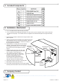
4 Installation - Electrical
10MAGLIFELOCK9
CAUTION
THE 10MAGLIEFLOCK9 IS DESIGNED TO BE USED WITH A DC POWER
SOURCE ONLY.
DO NOT ATTEMPT TO USE THIS PRODUCT WITH A 24V STEP DOWN
TRANSFORMER AND A BRIDGE RECTIFIER OR SERIOUS DAMAGE WILL
OCCUR TO THE MAGLOCK. A 24V STEP DOWN TRANSFORMER AND
BRIDGE RECTIFIER CIRCUIT WILL YIELD VOLTAGE ABOVE 29V, WHICH
EXCEEDS THE LIMITS OF THE SPIKE SUPPRESSION CIRCUIT IN THE
MAGLOCK, CAUSING PRODUCT FAILURE.
IT IS HIGHLY RECOMMENDED THAT ONLY A FILTERED DC POWER
SOURCE BE USED TO POWER THE 10MAGLIFELOCK9. BEA
RECOMMENDS THE 10PS12-24 OR SIMILAR QUALITY POWER SUPPLY.
12 VDC
POWER
SUPPLY
RED
WHITE
+
-
BLACK
GREEN
24 VDC
POWER
SUPPLY
RED
WHITE
+
-
BLACK
GREEN

Page 2 of 2 75.5884.01 20160419
7 Company Contact
1. Inspect the frame header to determine if an angle bracket or ller
plate is required.
2. Fold the enclosed mounting template on the dotted line and then
mark and drill two 1/8” (3.1 mm) holes as indicated. Place the
template against the cabinet door or drawer and header on
the lock jamb side of the frame.
3. Disassemble the mounting plate from the maglock
assembly. Insert (2) M4 x 25 mm screws into the
mounting plate holes and secure. Do not tighten
these screws fully until the maglock is properly
aligned.
4. Gently tap guide pins into the rear side of the
armature. Drill matching holes on the cabinet
door or drawer to receive these pins.
5. Align armature/strike plate to cabinet door
or drawer and then drill a 5/8” (16mm) hole
for sexnut. Using the M5 x 32 mm
hex head screw and enclosed Allen key,
mount armature to cabinet door or drawer
using two metal and one rubber washers.
6. Reassemble maglock assembly to mounting plate.
7. Make electrical connection (See Item 4).
8. Ensure that armature/strike plate can be shaken slightly.
This will permit full armature contact and maximize holding force.
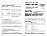
6 Installation - Mechanical
ARMATURE /
STRIKE PLATE
MOUNTING PLATE
MOUNTING
SCREWS
MAGLOCK
ASSEMBLY
MOUNTING PLATE
ASSEMBLY SCREWS
GUIDE PINS
ARMATURE / STRIKE
PLATE BOLT
24/7 Tech Support: 1-800-407-4545 | Customer Service: 1-800-523-2462 | General Tech Questions: T[email protected] | Tech Docs: www.beasensors.com
WASHERS
5 Included Components
Tip 1: DO NOT touch the lock face with your hands.
Tip 2: Should the surface plating be damaged, use a soft, clean dry cloth or abrasive cloth to clean the lock face.
DO NOT use sand paper. A rust inhibitor can the be applied to the armature/strike plate and maglock assembly
face.
-
 1
1
-
 2
2


Ask a question and I''ll find the answer in the document
Finding information in a document is now easier with AI
Related papers
-
BEA DELAYED EGRESS MAGLOCK KIT User guide
-
-
-
-
-
-
-
-
BEA MAGLOCKS 1200LB User guide
-
Other documents
-
Eclipse ACC-900 Quick Manual
-
Hager 2942 Installation guide
-
Gianni Industries GL1200-FS-IOTB Installation guide
-
Hagerco 2941 - Magnetic Lock Installation guide
-
-
Assa Abloy MGL-01500ALS Series Installation guide
-
SECO-LARM E-942FC-1K3SQ Owner's manual
-
-
-
 SECO-LARM USA Door E-941DA-1K2P User manual
