Gianni Industries GS705-30/35/35TD Installation guide

Type
Installation guide

Gianni Industries GS705-30/35/35TD is a heavy-duty electric lock designed to provide secure locking for various door applications. With a shear holding force of up to 2,200 lbs, it ensures reliable locking even for heavy doors. The lock features a self-regulating power input, accepting both 12VDC and 24VDC, making it adaptable to different power sources. Additionally, it includes a built-in magnet bond sensor with SPDT relay output, allowing for easy integration with access control systems.

Gianni Industries GS705-30/35/35TD is a heavy-duty electric lock designed to provide secure locking for various door applications. With a shear holding force of up to 2,200 lbs, it ensures reliable locking even for heavy doors. The lock features a self-regulating power input, accepting both 12VDC and 24VDC, making it adaptable to different power sources. Additionally, it includes a built-in magnet bond sensor with SPDT relay output, allowing for easy integration with access control systems.

GS-705 Shear Lock Installation Instruction
Specifications
Connecting Diagram
4-1
Auto Relocking timer
Shorten
Install the magnet assembly into the door frame before installation the armature assembly into the door leaf. The magnet
assembly requires space to run wires, as wall as space for the recesses portion of the unit. However, make sure that the position
selected for the magnet assembly leaves enough room on the door to install the armature assembly.
Unbalanced air conditioning (stack pressure) can hinder door alignment and must be corrected to help insure positive locking. It
is important to note that the Shear Locks need a regulated 12VDC (or 24VDC) at the lock, and use the highest quality door closer
only. Positive centering door closers are required for all double acting door applicators to help attain consistent dead center
alignment. Also the door latching problems must be corrected prior to installation.
Dimensions
30
1
4
7
2
6
7
12
5
6
3
4
(35)
Unit: mm
30
6
1
47
2
5
1
3
4
(35)
GS-705-35
GS-705-30
Shear Holding Force
Power Input
Door Gap
Operating Temp
GS-705-35 Current Draw
GS-705-30 Current Draw
Monitoring Output
Finish
Caution:
Make sure that the "+"
a n d " - " w i r e a r e
connected correctly.
Fai l ure t o ob s er v e
polarity will result in a
short circuit and is not
covered by products
warrant.
+
-
Power
supply
+
-
N.O.
COM.
N.C.
Power
Input
Magnet bond
sensor output
The Shear Locks may be wired to one
o f t w o d i f f e r e n t e l e c t r i c a l
configurations. An auto locking time
d e l a y i s r e c o m m e n d e d fo r al l
installations to delay relocking 1~6
seconds after initial door closure.
This will insure the door is fully
closed and at rest to obtain optimum
alignment before the Shear Lock is
energized.
Magnet bond sensor
output, SPDT relay :
1A/30 VDC
Control Device
N.C. contact or Access Relay
Copyright Gianni Industries, Inc. All Rights Reserved.
P-MU-GS705 Publish: 2015.03.26
Magnet
Flat Lug
Tapping screw
Fixing screw
Bulge Lug
Fixing Lug
Armature
2,000lbs (GS705-30)
12~24VDC (self-regulating)
Pull in: 1.85A ,Holding: 0.45AMP/12VDC
Pull in: 1.1A ,Holding: 0.25AMP/24VDC
Pull in: 1.8A ,Holding: 0.45AMP/12VDC
Pull in: 1.1A ,Holding: 0.25AMP/24VDC
(At temperature 20°C)
NOTE: The unit does not require initial voltage
increase to operate.
Magnet and Armature: Zinc plated,
Housing: Black powder coated
Magnet bond sensor output, SPDT rating
1AMP/30VDC dry contact
3mm (1/8) maximum
-30°C to +50°C
1~6 seconds adjustable (Default: 3 sec)
Important Notes
2,200lbs (GS705-35)
1~15 seconds adjustable (Default: 3 sec)
For GS705-35TD only
4-2
1. Make sure the gap between the door top rail and frame
header is within 3mm. adjust the gap as required.
2. Adjust single acting door and door closer to insure the
door settles immediately and is fully closed . (Adjust
double acting door and POSITIVE CENTERING DOOR
CLOSER to insure the door settles immediately and is fully
closed and rest in the dead center of the frame.)
3. Locate the vertical centerline of the magnet and
armature as possible to the leading door edge.
4. Determine the horizontal centerline of the door top rail
thickness. The Armature centerline will be the same. Mark
the door per template.
5. Before determining the frame header centerline single
acting door must be fully closed. Double acting doors must
be fully closed and rest in the dead center of the frame.
Mark the frame header per the template. Prepare the door
and frame per the template.
6. When installing GS-705, mark the timer adjustment as
required and test the locking time delay prior to mounting
in the frame. The locking time delay is field adjustable for
1~6 seconds and is factory set at approximately 3
seconds.
7. Install the Shear lock and armature with the auto
relock switch assembly towards the leading edge of the
door. For proper operation the armature must be adjusted
upward as close as possible and parallel to the Shear Lock
without interfering with opening and closing of the door.
Proper operation cannot be expected with more than 3 mm
gap between the armature and the magnet. Use the key
wr e nc h pro v id e d t o adj u st t he a rm a tu r e v ert ica l
adjustment screws.
8 With the door closed turn the lock power on, check the
lateral alignment. The armature locking bolt should be
centered to magnet keep hole. Adjust the locking time
delay(GS-705) to avoid early activation and help insure
positive locking on door closure. Adjust inward to delay
Shear Lock activation. Don't adjust higher than the
armature rest position.
9 Repeat steps 7,8 as necessary following shear lock
replacement. Cycle the door and Shear Lock several times
after the completion of the installation.
Use tapping
Screws for
wooden door
Flush Installation
Bulge Lugs is used when fixing screws cannot fix Fixing Lugs
on the door frame due to the shallow door frame. When the
situation happens, use the Bulge Lugs to increase the
thickness of the frame.
Flat Lugs is used when the door frame is deep, and to prevent
the Electromagnetic Lock or the Armature Plate caved in, add
flat lugs to raise the plane (level) of the Electromagnetic Lock
face or the Armature Plate face to the door frame surface.
Magnet Assembly
Armature Assembly
Position Sensor
Keep Hole
Armature vertical adjustment screws
Locking Bolt
Push-off button
Sensor Magnet
Le
a
di
n
g e
dg
e o
f d
oor
k
ey w
re
nch
T h e M a x i m u m G a p
between the Lock and
Armature plate is 3 mm
Using suppl i e d k e y wrench to
adjust armature plate to approx. 3
mm of gap between magnet and
armature.
Copyright Gianni Industries, Inc. All Rights Reserved.
P-MU-GS705 Publish: 2015.03.26
4-3
Unit: mm
Brack etOpt ional
Semi- Surface Installation
Surface Installation
Blind Nut Installation
SMB-001 Bracket For GS-705-35
Surface m o u nt installation Identify the
insufficient thickness / width of the door leaf
or frame header and inspect to determine if
SMB-001 bracket is required.
The GS-705-35 may also be fitted
semi-surface with the use of the SMB-001
Bracket. The magnet should be fitted to
the door transom and the housing holding
the armature on to the door. It is vital that
a maximum gap of 3mm exists between
the magnet and the armature, to allow
correct operation.
The GS-705-35 may also be fitted
surface mounted using 2pcs of the SMB-
001 Bracket. The housing holding the
magnet should be fitted above the door
and the housing holding the armature on
to the door. It is vital that a maximum gap
of 3mm exists between the magnet and
the armature, to allow correct operation.
Using supplied key wrench to adjust
armature plate to approx. 3 mm of gap
between magnet and armature.
Using supplied key wrench to adjust
armature plate to approx. 3 mm of gap
between magnet and armeture.
Drill 9.4mm holes
for M6 Blind Nuts.
Blind Nut
M6 Scr ew
Magnet Assem bl y
Surf ace Mount
Armat ure Assem bl y
Metal Door
Header
3mm
Blind Nut
Blind Nut
M6 Scr ew
M6 Scr ew
Magnet
Assem bly
Armat ure
Assem bly
Metal Door
Header
3mm
Blind Nut
M6 Scr ew
Insert two Blind Nuts
into separate holes,
one for each fixing
screw.
Use the allen wrench.
To slowly tighten the
Blind Nut. (Don't
turning over)
This compress the
Blind Nut so that it
remains permanently
fixed in the frame.
Remove the tool. Use M6 Screws fixing
SMB-001brackets.
a
l
l
en
wr
ench
45
5
0
3
50
k
e
y wre
nch
key wr
e
n
c
h
Copyright Gianni Industries, Inc. All Rights Reserved.
P-MU-GS705 Publish: 2015.03.26
4-4
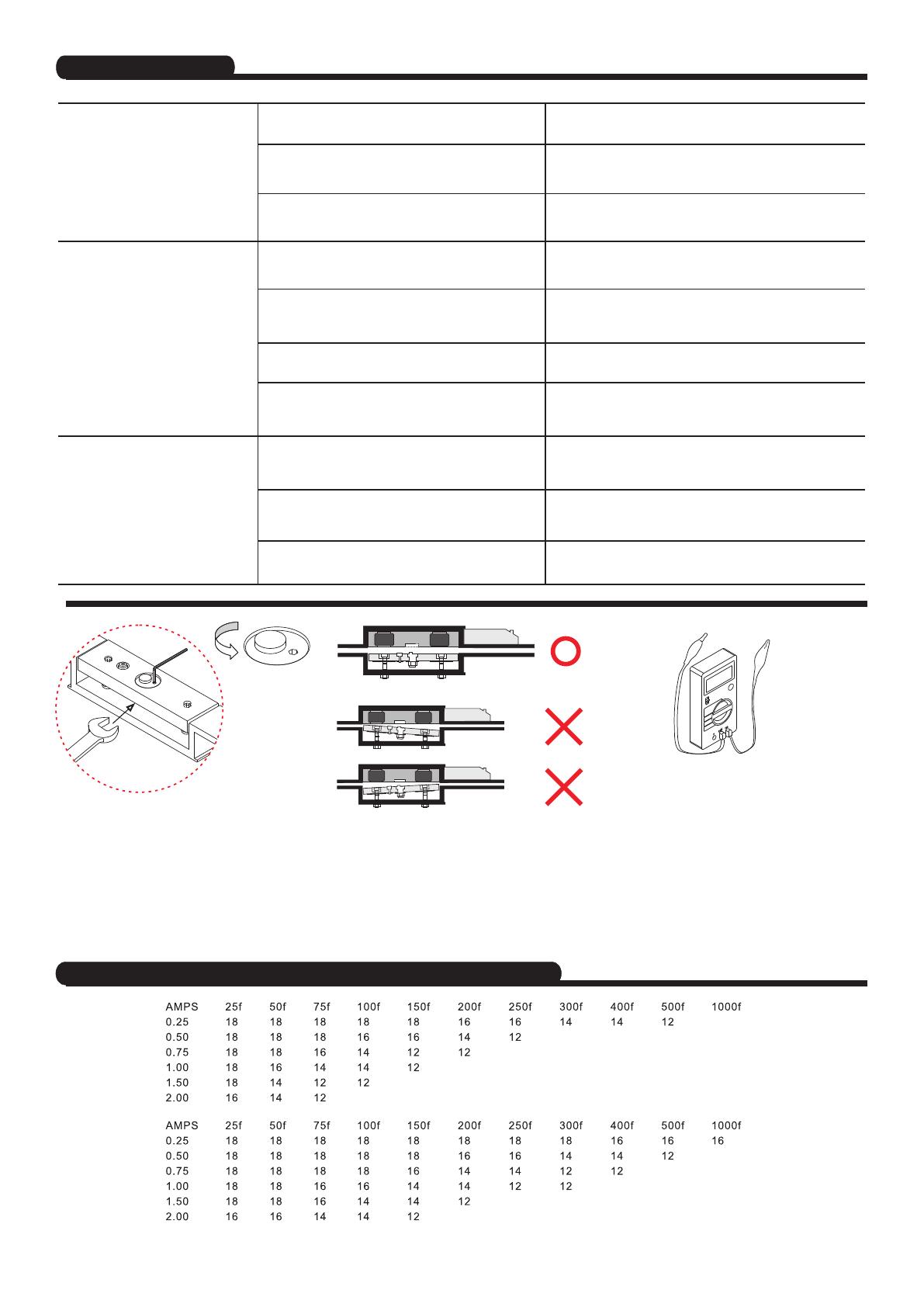
Distance in feet from power source to farthest locking device
Trouble Shooting
Minimum
Wire Gauge
for 12 VDC
Minimum
Wire Gauge
for 24 VDC
1
3
.
8
Door does not lock
No power.
Voltage and / or current is too low.
Problems
Possible Cause
Solution
The gap between the Armature Plate and the
Shear Lock is exceeding 3mm.
Adjust the Armature Plate and arrange the gap between
the Armature Plate and the Shear lock within 3mm.
Adjust the Armature Plate and arrange the gap between
the Armature Plate and the Shear lock within 3mm.
Electrically Checked with an Ammeter, it must be
powered with the correct input voltage and checked to
see if it draws the specified current.
Electrically Checked with an Ammeter, it must be
powered with the correct input voltage and checked to
see if it draws the specified current.
Adjust the Armature Plate and make sure the gap
between the Armature Plate and the Shear Lock is equal.
Adjust the locking bolt of the Armature Plate and make
sure it correctly seats inside the keep hole of the Shear
Lock.
Adjust the locking bolt of the Armature Plate and make
sure it correctly seats inside the keep hole of the Shear
Lock.
Adjust the Armature Plate and make sure the gap
between the Armature Plate and the Shear Lock is equal.
Adjust the setting of 'Locking time delay to appropriate.
Positive centering door closers are required for all
double acting door applicators to help attain consistent
dead center alignment.
T h e A r ma t u re P l a t e k e e p
r e p e a t i n g t h e m a g n e t i c
attracting motion.
The Armature Plate is not at the
right position and the locking
bolt cannot seat correctly into
the keep hole of the Shear
Lock.
Use spanner and allen wrench to release
the Locking Bolt on the Armature Plate.
Rotate the position of the Locking Bolt in
order to correctly seat inside the keep
hole of the Shear Lock.
Make sure the gap between the Shear
Lock and the Armature Plate are the same
while adjusting the gap.
Since the current draw, which operates
the Shear Lock, is large (1.8A/12VDC;
1A/24VDC), it is necessary to make sure
the condition of the wire is capable for
long distance usage. It is also necessary
to make sure the output current of the
Shear Lock is sufficient for the power that
the manufacturer listed.
The gap between the Armature Plate and the
Shear Lock is exceeding 3mm.
The gap between the Armature Plate and the
Shear Lock is unequal.
The locking bolt does not correctly seat inside the
keep hole of the Shear Lock.
The position of the locking bolt is not correct.
The gap between the Armature Plate and the
Shear Lock is unequal.
The setting of 'Auto Relocking time delay' is too
short.
The door leaf does not return back at the correct
position.
Copyright Gianni Industries, Inc. All Rights Reserved.
P-MU-GS705 Publish: 2015.03.26
  • Page 1 1
  • Page 2 2
  • Page 3 3
  • Page 4 4

Gianni Industries GS705-30/35/35TD Installation guide

Type
Installation guide

Gianni Industries GS705-30/35/35TD is a heavy-duty electric lock designed to provide secure locking for various door applications. With a shear holding force of up to 2,200 lbs, it ensures reliable locking even for heavy doors. The lock features a self-regulating power input, accepting both 12VDC and 24VDC, making it adaptable to different power sources. Additionally, it includes a built-in magnet bond sensor with SPDT relay output, allowing for easy integration with access control systems.

Ask a question and I''ll find the answer in the document

Finding information in a document is now easier with AI