Page is loading ...

Assembly Instructions
IF2008/PCIe, IF2008E

MICRO-EPSILON
MESSTECHNIK
GmbH & Co. KG
Königbacher Strasse 15
94496 Ortenburg / Germany
Tel. 0049/ 08542/168-0
Fax 0049/ 08542/168-90
e-mail: [email protected]
www.micro-epsilon.com
Interface board

IF2008/PCIe / IF2008E
Contents
1. Safety .......................................................................................................................................... 5
1.1 Symbols Used .................................................................................................................................................... 5
1.2 Warnings ............................................................................................................................................................ 5
1.3 Proper Environment ........................................................................................................................................... 5
2. Delivery ....................................................................................................................................... 5
3. System Requirements ................................................................................................................ 6
4. Technical Data ............................................................................................................................ 6
4.1 IF2008/PCIe Basis Board ................................................................................................................................... 6
4.2 IF2008E Expansion Board ................................................................................................................................. 6
5. Installation of IF2008/PCIe......................................................................................................... 7
6. Installation of Devices Driver, Windows 10 ............................................................................... 8
7. Hardware .................................................................................................................................... 9
7.1 View of IF2008/PCIe Basis Board ...................................................................................................................... 9
7.2 View of IF2008E Expansion Board .................................................................................................................. 10
8. Pin Assignments and Jumper Settings ................................................................................... 11
8.1 Sensor Interface ............................................................................................................................................... 11
8.2 Encoder Interface ............................................................................................................................................. 11
8.3 Sensor Power (IF2008/PCIe X7) ...................................................................................................................... 12
8.4 IO Interface (IF2008E X2) ................................................................................................................................. 12
8.5 Analog Interface (IF2008E X3) ......................................................................................................................... 12
8.6 Jumper/Switch Setting for Trigger Level.......................................................................................................... 13
8.7 Switch Setting for ADC Level ........................................................................................................................... 14

optoNCDT ILR 1183
9. Address assignment ................................................................................................................ 14
9.1 PCI Interface ..................................................................................................................................................... 14
9.2 Local Address Assignment .............................................................................................................................. 15
10. Register Description ................................................................................................................ 16
10.1 Transmit Register ............................................................................................................................................. 16
10.2 Fifo Data ........................................................................................................................................................... 17
10.3 Set- / Reset- / Latch Register ........................................................................................................................... 18
10.4 FIFO Volume .................................................................................................................................................... 19
10.5 FIFO Enable Register ....................................................................................................................................... 19
10.6 Interrupt Enable Register ................................................................................................................................. 20
10.7 Interrupt-Status-Register .................................................................................................................................. 20
10.8 Sensor Baud Rate ............................................................................................................................................ 21
10.9 Counter Control Register ................................................................................................................................. 21
10.10 Counter Preload ............................................................................................................................................... 24
10.11 Counter Value................................................................................................................................................... 24
10.12 Timer ................................................................................................................................................................ 24
10.13 ADC .................................................................................................................................................................. 25
10.14 Status ............................................................................................................................................................... 25
10.15 Input and Sensor Power Switch Status ........................................................................................................... 26
10.16 Output Register ................................................................................................................................................ 27
10.17 Mode Opto- and TxD Outputs ......................................................................................................................... 28
10.18 Mode Trigger Outputs, Latch Source and Sensor Power Switch ................................................................... 29
10.19 ADC Control Register ....................................................................................................................................... 31
10.20 Parity Enable Register ...................................................................................................................................... 33
10.21 Parity-Error-Register ......................................................................................................................................... 33
11. Wiring Recommendations ....................................................................................................... 34
11.1 Sensor ILD1420................................................................................................................................................ 34
11.2 Sensor ILD1750................................................................................................................................................ 35
11.3 Sensor ILD2300................................................................................................................................................ 36
11.4 Encoder Interface ............................................................................................................................................. 37
11.5 Optocoupler I/O ............................................................................................................................................... 38
12. Liability for Material Defects .................................................................................................... 39
13. Decommissioning, Disposal .................................................................................................... 39

Page 5
Safety
IF2008/PCIe / IF2008E
1. Safety
Board operation assumes knowledge of the assembly instructions.
1.1 Symbols Used
The following symbols are used in these assembly instructions:
Indicates a situation that may result in property damage if not avoided.
Indicates a user action.
i
Indicates a tip for users.
1.2 Warnings
Electronic devices can be damaged due to electrostatic discharge. Prior to installation of the interface
card(s), we recommend to touch a grounded surface in order to avoid electrostatic discharge. For that pur-
pose please touch a grounded surface, for example the metal housing of your computer.
> Damage to or destruction of the board.
1.3 Proper Environment
- Temperature range
Operation: 5 ... +40 °C (41 ... +104 °F)
Storage: -10 ... +40 °C (+50 ... +104 °F)
- Humidity: 5 - 95 % (no condensation)
- Pressure: Atmospheric pressure
2. Delivery
- 1 IF2008/PCIe and/or IF2008E interface board - 1 Assembly instructions
- 1 CD-ROM with software package, driver for windows ®10 - 1 Adapter for power supply
Check for completeness and shipping damage immediately after unpacking.
In case of damage or missing parts, please contact the manufacturer or supplier.

Page 6
System Requirements
IF2008/PCIe / IF2008E
3. System Requirements
- Processor (CPU) with 1 GHz clock rate or faster
- 2 GB RAM
- Windows ® 7 (32/64 Bit), Windows ® 10 (32/64 Bit)
- Free PCIe slot
- Minimum 10 MB free disk space on the hard disk
4. Technical Data
4.1 IF2008/PCIe Basis Board
Mechanics and environment
- Dimensions (PCB) approx. 110 x 105 mm, width: 1 slot
- Max. permitted ambient temperature +40 °C (+104 °F)
- 2x D-SUB female connectors HD 15-pin for sensor
connections
- 1x D-SUB male connector HD 15-pin for encoder signals
- 1x Tyco/AMP Commercial MATE-N-LOK connector (IDE
hard drive connector) for supply DC/DC-converter,
- 3x Tyco/AMP MicroMatch female connectors to IF2008E
PCI-Express bus
- PCI-Express x1 interface
- Target Interface (slave) according to specification Rev. 1.0
- Current consumption at +3,3 V approx. 0.5 A, without sen-
sors and encoders
- Power supply of encoders with +5 V from the PCI power
- Power supply of the sensors with +24 V from the PC power
supply
Sensor interface (X1 / X2)
- 4x RS422 drivers (2x TxD and 2x trigger out) and 2x RS422
receivers per connector (input/output frequency max. 5 MHz)
- Power supply of the sensors 24 V
Encoder interface (X3)
- Interface for two encoders with 1 Vss, RS422 (difference) or
TTL (single-ended) signals
- Power supply of the encoders with +5 V from PCI power
supply without galvanic isolation (current consumption de-
pendent on the connected encoders)
- Interpolation programmable from 1 to 64 times for encoders
with 1 Vss signals
(input frequency max. = [3.2 MHz / interpolation] ≤ 800 kHz)
- Evaluation programmable from 1 to 4 times in case of
encoders with:
RS422- / Difference signals
(input frequency max. 800 kHz)
TTL- / single-ended-signals
(input frequency max. 400 kHz)
4.2 IF2008E Expansion Board
Mechanics and environment
- Dimensions (PCB) approx. 71 x 102 mm, width: 1 slot
- Max. permitted ambient temperature +40 °C (+104 °F)
- 1x D-SUB female connector HD 15-pin for sensor connections
- 1x D-SUB female connector 9-pin for IO interface
- 1x D-SUB male connector 9-pin for analog inputs
- 3x MicroMatch female connectors for connection to IF2008/
PCIe

Page 7
Installation of IF2008/PCIe
IF2008/PCIe / IF2008E
Sensor interface (X1)
- Identical to IF2008/PCIe (X1)
I/O-Interface (X2)
- 4x Optocoupler inputs, input current max. 5 mA,
input frequency max. 1 Mhz
- 4x Optocoupler outputs, output current max. 20 mA,
output frequency max. 1 Mhz
5. Installation of IF2008/PCIe
For installing the IF2008/PCIe please proceed as follows:
Switch off your computer as well as all peripheral devices. Unplug
the power cords.
Open the housing of your computer. For further details please find
the instruction in your computer manual.
Find a PCI extension slot for the IF2008/PCIe card which is not as-
signed. Remove the cover of the slot, keep hold of the card on the
top edge while carefully pushing it into the slot. The card must be
fastened to the mounting using bolts.
i
IF2008/PCIe requires on X7 an external supply voltage through
PC!
Connect X7 of the IF2008/PCIe with the power supply of the PC.
Therewith you support the necessary power supply of the DC-/DC
converter.
The IF2008E has to be fastened to a mounting which is not as-
signed using bolts. Interconnect the interface cards IF2008/PCIe
and IF2008E. Connect the plug connectors of the same numbering
using the cables which are included in delivery, that means X4 with
X4, X5 with X5, X6 with X6.
Close the housing of your computer and switch
on the computer as well as the peripheral de-
vices.
Analog interface (X3)
- 2x ADC channels
- Input voltage range 0-5 V, 0-10 V, ±5 V, ±10 V, sepa-
rately adjustable for each channel via DIP switch
- Resolution 16 bits
- Offset error max. ±3 mV
- Gain error max. ±5 mV
- Conversion rate max. 150 kHz per channel
X7
Power
supply
PC
IF2008/PCIe
IF2008E

Page 8
Installation of Devices Driver, Windows 10
IF2008/PCIe / IF2008E
6. Installation of Devices Driver, Windows 10
i
The installation of a driver may be regulated by your IT
department. Install drivers together with your IT department
or have a time-limited admin right set up on your PC.
The following notes describe the installation of the driver via the
device manager.
Start the device manager and click the Update driver
entry.
Choose Browse my computer for driver software.
Copy the driver file into the path to MEDAQLib <...Driver/
IF2008>.
Click the Browse button and enter the path to the driver
file. Check the Include subfolders box.
In the following screen, set the check mark for Trust
software from ... and click the Install button.
The operating system reports the successful installation of
the driver, the device manager lists the interface card.

Page 9
Hardware
IF2008/PCIe / IF2008E
7. Hardware
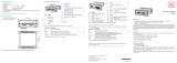
7.1 View of IF2008/PCIe Basis Board
X1 = Sensor
connection 1 and 2
X2 = Sensor
connection 3 and 4
X3 = Encoder
connection 1 and 2
X4 ... X6 = Connector for IF2008E connection
X7 = Connection 12 V power
Fig. 1: View of board IF2008/PCIe Basis Board

Page 10
Hardware
IF2008/PCIe / IF2008E
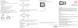
7.2 View of IF2008E Expansion Board
X1 = Sensor
connection 5 and 6
X2 = Connection for
IO signals
X3 = Connection for A/D
converter
Fig. 2: View of board IF2008E expansion board
X4 ... X6 = Connection for IF2008/PCIe connection
S5 and S6 = Switch for positive trigger level
S11 ... S15 = Switch for ADC level 1
S21 ... S25 = Switch for ADC level 2

Page 11
Pin Assignments and Jumper Settings
IF2008/PCIe / IF2008E
8. Pin Assignments and Jumper Settings
8.1 Sensor Interface
IF2008/PCIe X1 and X2, IF2008E X1
Pin Signal
1 Sensor 1 TxD-
2 Sensor 1 TxD+
3 Sensor 1 RxD-
4 Sensor 1 RxD+
5 Power supply 0 V
6 Sensor 1 TRG+
7 Sensor 1 TRG-
8 Sensor 2 TRG+
9 Sensor 2 TRG-
10 Power supply +24 V
11 Sensor 2 TxD-
12 Sensor 2 TxD+
13 Sensor 2 RxD-
14 Sensor 2 RxD+
15 GND
Fig. 3: Pin assignment for sensor interface
8.2 Encoder Interface
IF2008/PCIe X3
Pin Function
1 Encoder 1 Track A+
2 Encoder 1 Track A-
3 Encoder 2 Track A+
4 Encoder 2 Track A-
5 VCC (+5 V)
6 Encoder 1 Track B+
7 Encoder 1 Track B-
8 Encoder 2 Track B+
9 Encoder 2 Track B-
10 GND
11 Encoder 1 Track R+
12 Encoder 1 Track R-
13 Encoder 2 Track R+
14 Encoder 2 Track R-
15 GND
Fig. 4: Pin assignment for encoder interface
i
The pin assignment is not compatible with IF2004B!

Page 12
Pin Assignments and Jumper Settings
IF2008/PCIe / IF2008E
8.3 Sensor Power (IF2008/PCIe X7)
Pin Function
1 +12 V
2 GND
3 GND
4 n.c.
Fig. 5: Pin assigment of sensor power
8.4 IO Interface (IF2008E X2)
Pin Function
1 OUT 1
2 OUT 2
3 OUT 3
4 OUT 4
5 GND
6 IN 1
7 IN 2
8 IN 3
9 IN 4
Fig. 6: Pin assignment IO interface
8.5 Analog Interface (IF2008E X3)
Pin Function
1 Input signal 1
2 Analog GND
3 Input signal 2
4 Analog GND
5 n.c.
6 n.c.
7 n.c.
8 n.c.
9 n.c.
Fig. 7: Pin assignment analog interface

Page 13
Pin Assignments and Jumper Settings
IF2008/PCIe / IF2008E
8.6 Jumper/Switch Setting for Trigger Level
By means of the switches S5 and S6 (IF2008E) the positive trigger level for the sensor channels 5 and 6
(IF2008E) can be selected. The negative output always has LVDS level.
Fig. 8: Switch settings trigger level IF2008A
Switch Setting Trigger output +
S5 to S6
LVn LVDS level for sensor n TRG+
CMn 3.3 V CMOS level for sensor n TRG+
Fig. 9: Switch settings trigger level

Page 14
Address assignment
IF2008/PCIe / IF2008E
8.7 Switch Setting for ADC Level
VIN Sx1 Sx2 Sx3 Sx4 Sx5
0-5 V ON ON ON ON
0-10 V ON ON ON ON
±5 V ON ON ON
±10 V OFF ON ON
Fig. 10: Switch settings ADC level for ±10 V Fig. 11: Switch settings ADC level
9. Address assignment
9.1 PCI Interface
Interface: PCI-Express x1 interface
Access: Memory space 40 Hex addresses
Base address: Automatically assigned by operating system
Adr. Byte 3 Byte 2 Byte 1 Byte 0 Value (Hex)
00h Device ID Vendor ID 1910 1204
18h Base Address Local Memory Space xxxx xxxx
2C Subsystem ID Subsystem Vendor ID 2008 1204
Fig. 12: Header configuration

Page 15
Address assignment
IF2008/PCIe / IF2008E
9.2 Local Address Assignment
Base addr. + Write access Read access
00h Transmit register FIFO data
02h Set- / Reset- / Latch register FIFO volume
04h FIFO enable register FIFO enable register
06h Interrupt enable register Interrupt status register
08h Sensor 1 baud rate Reserved
0Ah Sensor 2 baud rate Reserved
0Ch Sensor 3 baud rate Reserved
0Eh Sensor 4 baud rate Reserved
10h Sensor 5 baud rate Reserved
12h Sensor 6 baud rate Reserved
14h Counter control register 1 Counter control register 1
16h Counter control register 2 Counter control register 2
18h Counter 1 preload LSW Counter 1 LSW
1Ah Counter 1 preload MSW Counter value 1 MSW
1Ch Counter 2 preload LSW Counter 2 LSW
1Eh Counter 2 preload MSW Counter value 2 MSW
20h Timer 1 frequency ADC 1
22h Timer 1 pulse width ADC 2
24h Timer 2 frequency Status, FPGA- / hardware version
26h Timer 2 pulse width Input and status power switch
28h Timer 3 frequency Reserved
2Ah Timer 3 pulse width Reserved

Page 16
Register Description
IF2008/PCIe / IF2008E
Base addr. + Write access Read access
2Ch Timer clock splitter Timer clock splitter
2Eh Output register Output register
30h Mode opto- and TxD outputs Mode opto- and TxD outputs
32h Trigger Outputs Mode Mode trigger outputs, latch source and sensor power switch
34h ADC control register ADC-Kontrollregister
36h Parity enable register Parity error
Fig. 13: Local address assignment
10. Register Description
10.1 Transmit Register
Base addr. + 00h (write access)
Bit 15 14 13 12 11 10 9 8 7 6 5 4 3 2 1 0
S6 S5 S4 S3 S2 S1 D7 D6 D5 D4 D3 D2 D1 D0
Selection sensor channel Data bits
Fig. 14: Transmit register
Bit 0 to 7 Include the data for the transmit register
Bit 8 to 15 Select the sensor channel
Bit 8 = 1 > Data are output on the sensor channel S1
Bit 9 = 1 > Data are output on the sensor channel S2
Bit 13 = 1 > Data are output on the sensor channel S6
Bit 14 ... 15 > free
Immediately on the write access to the address „0“, the data with the bit 8 to 13 selected sensor channel are transmitted. The baud
rate for the transmit register is automatically adapted to the selected sensor channel. In case that the data output is effected on more
channels, the baud rate of the best channel is used.

Page 17
Register Description
IF2008/PCIe / IF2008E
10.2 Fifo Data
Base addr. + 00h (read access)
Bit 15 14 13 12 11 10 9 8 7 6 5 4 3 2 1 0
C7 C6 C5 C4 C3 C2 C1 C0 D7 D6 D5 D4 D3 D2 D1 D0
Code bits Data bits
Fig. 15: FIFO data memory
Bit 0 to 7 Include the data buffered
Bit 7 to 15 Mark the data code
Code bits
Bytes 0 to 7
Channel 0 to 7
Data source 0 to 3
C7 C6 C5 C4 C3 C2 C1 C0
C7 C6 Daten source
0 0 Sensor
0 1 Encoder
1 0 Switching input (IN 1 ... 4 > channel 0, RxD 1 ... 6 > channel 1)
1 1 ADC
Fig. 16: FIFO data memory - data sources

Page 18
Register Description
IF2008/PCIe / IF2008E
10.3 Set- / Reset- / Latch Register
Base addr.. + 02h (write access)
Bit Function
0
Delete counter 1
1
Load counter 1
2
Latch counter 1
3
Reference counter 1
4
Delete counter 2
5
Load counter 2
6
Latch counter 2
7
Reference counter 2
8
Start ADC1 conversion
9
Start ADC2 conversion
10
Delete FIFO
11 to 15
Reserved
Fig. 17: Set- / Reset- / Latch register
i
By means of the bits 0 to 2 and 4 to 6, the counters can be either deleted or loaded independently of
the counter control register by the software, (addr. 14h and addr. 16h). Furthermore, the counter rea-
ding can be transferred into the latch register.
If a counter latch or load function, which should only operate in connection with a reference marker
signal is settled by the counter control register (addr. 14h and addr. 16h); this is subject to approval by
setting bit 3 or bit 7. On setting bit 3 or bit 7 the status bits 0 and 1 or 2 and 3 are reset.
All bits only need to be set, resetting them is not necessary.
After power interruption, all bits are set to “0”.

Page 19
Register Description
IF2008/PCIe / IF2008E
10.4 FIFO Volume
Base addr. + 02h (read access)
Bit Function
0 to 14 FIFO data volume (0 to 32767)
15 permanently 0
Fig. 18: FIFO volume
The dataset is transferred automatically into the FIFO data
memory on receipt. By means of a report of the FIFO volume
the FIFO data amount can be calculated. The order and speed
regarding buffering the data received, is similar to the data
stream of the receiving register. In case that the FIFO is not
readout quickly enough, it offers the latest 32768 data sets.
10.5 FIFO Enable Register
Base addr. + 04h (read and write access)
Bit Function
0 0 = FIFO for sensor channel 1 disabled
1 = FIFO for sensor channel 1 enabled
1 0 = FIFO for sensor channel 2 disabled
1 = FIFO for sensor channel 2 enabled
2 0 = FIFO for sensor channel 3 disabled
1 = FIFO for sensor channel 3 enabled
3 0 = FIFO for sensor channel 4 disabled
1 = FIFO for sensor channel 4 enabled
4 0 = FIFO for sensor channel 5 disabled
1 = FIFO for sensor channel 5 enabled
5 0 = FIFO for sensor channel 6 disabled
1 = FIFO for sensor channel 6 enabled
Bit Function
6 0 = FIFO for encoder channel 1 disabled
1 = FIFO for encoder channel 1 enabled
7 0 = FIFO for encoder channel 2 disabled
1 = FIFO for encoder channel 2 enabled
8 0 = FIFO for state of external inputs IN 1..4 disabled
1 = FIFO for state of external inputs IN 1..4 enabled
9 0 = FIFO for state of RxD inputs (sensor 1..6) disabled
1 = FIFO for state of RxD inputs (sensor 1..6) enabled
10 0 = FIFO for ADC 1 disabled
1 = FIFO for ADC 1 enabled
11 0 = FIFO for ADC 2 disabled
1 = FIFO for ADC 2 enabled
12 0 = FIFO is disabled for sensor 1 and 2 if ext.
input IN 1 is active
1 = IN 1 does not affect FIFO
13 0 = FIFO is disabled for sensor 3 and 6 if ext.
input IN 2 is active
1 = IN 2 does not affect FIFO
14 0 = FIFO is disabled for encoder 1 and 2 if ext.
input IN 3 is active
1 = IN 3 does not affect FIFO
15 0 = FIFO is disabled for ADC 1/2; IN 1..4; RxD 1..6 if
ext. input IN 4 is active
1 = IN 4 does not affect FIFO
Fig. 19: FIFO enable register

Page 20
Register Description
IF2008/PCIe / IF2008E
10.7 Interrupt-Status-Register
Base addr. + 06h (read access)
Bit Function
0 1 = Interrupt requirement if FIFO level exceeds 50 %
1 1 = Interrupt requirement if FIFO level exceeds 75 %
2 1 = Interrupt requirement on overflow Timer 1
3 1 = Interrupt requirement on overflow Timer 2
4 1 = Interrupt requirement on overflow Timer 3
5 1 = Interrupt requirement if external input IN 1 is acti-
vated
6 1 = Interrupt requirement if external input IN 2 is acti-
vated
7 1 = Interrupt requirement if external input IN 3 is acti-
vated
8 1 = Interrupt requirement if external input IN 4 is acti-
vated
9 - 15 Reserved
Fig. 21: Interrupt status register
i
The interrupt state register informs by which source(s)
the interrupt requirements have been generated. One
interrupt requirement can be effected by using more than
one source at the same time. In case that no state bit is
set, the interrupt requirement was not generated by the
IF2008A but by another hardware.
10.6 Interrupt Enable Register
Base addr. + 06h (write access)
Bit Function
0 1 = Enable interrupt requirements if FIFO is filled with
more than 50 %
1 1 = Enable interrupt requirements if FIFO is filled with
more than 75 %
2 1 = Enable interrupt requirements on overflow Timer 1
3 1 = Enable interrupt requirements on overflow Timer 2
4 1 = Enable interrupt requirements on overflow Timer 3
5 1 = Enable interrupt requirements if external input IN 1
is activated
6 1 = Enable interrupt requirements if external input IN 2
is activated
7 1 = Enable interrupt requirements if external input IN 3
is activated
8 1 = Enable interrupt requirements if external input IN 4
is activated
9 - 15 Reserved
Fig. 20: Interrupt enable register
i
The interrupt generation is controlled by a trigger flan-
ge, i.e., an interrupt requirement is only effected if the
corresponding bit is set in the interrupt enable register.
Furthermore, the appropriate source has to change from
the inactive into the active state. Several bits can be set at
the same time.
/