Page is loading ...

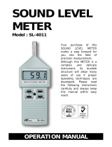
SOUND LEVEL
METER
Model : SL-4010
Your purchase of this
SOUND LEVEL METE
R
marks a step forward for
you into the field of
precision measurement.
Althou
g
h this METER is a
complex and delicate
instrument, its durable
structure will allow many
years of use if proper
operatin
g
techniques are
developed. Please read
the followin
g
instructions
carefully and always keep
this manual within easy
reach.
OPERATION MANUAL

TABLE
OF
CONTENTS
1. FEATURES...............................................................1
2. SPECIFICATIONS..................................................... 1
3. FRONT PANEL DESCRIPTION....................................3
3-1 Electric condenser microphone...........................3
3-2 Display............................................................. 3
3-3 Range upper / lower indicator............................3
3-4 Range switch.................................................... 3
3-5 External calibration VR......................................
.
3
3-6 Power OFF/ON/Hold switch................................3
3-7 Battery compartment / Cover.............................3
4. MEASURING PROCEDURE.........................................4
5. REPLACEMENT of BATTERY......................................4
6. CALIBRATION .........................................................5
7. FREQUENCY WEIGHTING CHARACTERISTICS
OF " A " NETWORKS................................................
.
6

1. FEATURES
* Large LCD display, easy to read.
* Characteristic of " A " frequency weighting network are
designed to meet IEC 61672 class 2.
* " Fast " time weighting characteristic mode.
* Build in adj. VR is available for easy calibration.
* Condenser microphone for high accuracy & long-term
stability.
* Hold function to freeze the display value.
* Warning indicator for over and under range.
* LCD display for low power consumption & clear
read-out even in bright ambient light condition.
* Used the durable, long-lasting components, including a
strong, light weight ABS-plastic housing case.
* Small and light weight design allow one hand operation.
* Low battery indicator.
* High quality with economical cost.
2. SPECIFICATIONS
Display 18 mm ( 0.7" ) LCD ( Liquid Crystal
Display ), 3 1/2 di
g
its.
Measurement
35 to 130 dB, 3 ran
g
es :
Ran
g
eran
g
e 1 - 35 to 80 dB,
ran
g
e 2 - 50 to 100 dB,
ran
g
e 3 - 80 to 130 dB,
*Each ran
g
e with warnin
g
indicator for
over & under load.
Resolution 0.1 dB.
Measurement 31.5 Hz to 8,000 Hz.
Frequency
Frequency Characteristics of " A " frequency
Wei
g
htin
g
wei
g
htin
g
network.
*The " A wei
g
htin
g
" characteristic is
simulated as "Human Ear Listin
g
"
response.
1

Time Wei
g
htin
g
Default to " Fast " time wei
g
htin
g
characteristics.
* " Fast time wei
g
htin
g
" is simulated the
human ear response character.
Accuracy Characteristics of " A " frequency
(
23± 5
)
℃
wei
g
htin
g
network meet IEC 61672
class 2.
Under 94 dB input si
g
nal, the accuracy
are :
31.5 Hz ± 3.5 dB
63 Hz ± 2.5 dB
125 Hz ± 2.0 dB
250 Hz ± 1.9 dB
500 Hz ± 1.9 dB
1
K
Hz ± 1.4 dB
2
K
Hz ± 2.6 dB
4
K
Hz ± 3.6 dB
8
K
Hz ± 5.6 dB
Remark :
T
he above spec. are tested under th
e
environment RF Field Strength less tha
n
3 V/M & frequency less than 30 MH
z
only.
Calibrator B & K (Bruel & k
j
aer), multi-fuction
acoustic calibrator, model : 4226.
Microphone Electric condenser microphone.
Size of microphone 1/2 inch standard size.
Calibration VR Build in external calibration VR, easy to
calibrate on 94 dB level by screw driver.
Data Hold Hold function to freeze the display value.
Operatin
g
Temp. 0 to 50 ( 32 to 122 ).℃℉
Operatin
g
Humidity Less than 80% RH.
Power Supply
Alkaline or Heavy duty type, 9V d.c.
006 P, MN1604(PP3) or equivalent.
Power Consumption Approx. DC 6 mA.
Dimension 250 x 70 x 28 mm ( 9.9 x 2.8 x 1.1 inch ).
Wei
g
ht 250
g
/0.55 LB ( includin
g
battery ).
Standard Instruction Manual ...................... 1 PC.
Accessories
Optional 94 dB Sound Calibrator,
Accessories Model : SC-941, SC-942.
Hard carryin
g
case, Model : CA-06.
2

3. FRONT PANEL DESCRIPTION
3-1 Electric condenser microphone
3-2 Display
3-3 Range upper / lower indicator
3-4 Range switch
3-5 External calibration VR
3-6 Power ON/OFF/Hold switch
" 1 " = Power ON " 0 " = Power OFF
3-7 Battery compartment / Cover
3

4. MEASURING PROCEDURE
1)Slide the " Power ON/OFF/Hold switch " ( 3-6, Fig. 1 ) to
the " 1 " position will power on the meter.
" 1 " = Power ON. " 0 " = Power OFF.
2)Determine proper measuring range by selecting the
" Range switch " ( 3-4, Fig. 1 ) to minimize the tolerance of
readout. When left corner of LCD show " "
( Range upper / lower indicator, 3-3, Fig. 1 ), it shows
the dB range selection is upper or lower setting. Slide
range switch to other range for measuring.
3)Hold the instrument in hand and point the microphone at
measured noise source, the sound level will be displayed
on " dB " ( decibel) unit.
4)During the measurement, if slide the " Power
ON/OFF/Hold switch " ( 3-6, Fig. 1 ) to the " Hold "
position will freeze the display value. If slide the
" Power ON/OFF/Hold switch " ( 3-6, Fig. 1 ) to the " 1 "
position. then the display will make the measurement
continually.
5. REPLACEMENT OF BATTERY
1)When the left corner of LCD display show " BAT ",
it indicate a normal battery output of less than
6.5 V - 7.5 V. It is necessary to replace the battery.
However, in-spec. measurement may still be made for
several hours after LOW BATTERY INDICATOR
appears before the instrument become inaccurate.
2)Slide the Battery Cover ( 3-7, Fig. 1 ) & take the battery
away from the battery compartment..
3)Replace with 9V battery ( Alkaline or Heavy duty type,
006 P, MN1604/PP3 or equivalent ) and reinstate the cover.
4

6. CALIBRATION
*
The sound level meter is built in the internal
" External calibration VR " ( 3-5, Fig. 1 ) on the front
panel.
*
Please according the following procedures to calibrate
the instrument accurately, if it is necessary.
1) Prepare the optional " SOUND CALIBRATOR, model:
SC-941, SC-942 or other equivalent sound calibrator.
Power on the Sound Calibrator & plug calibrator output
into the " Electric condenser micro- phone " ( 3-1, Fig. 1 )
of the Sound Level Meter.
2) Slide the " Range switch " ( 3-4, Fig. 1 ) to " 50 - 100 dB "
position.
3) Carefully adjust the " Calibration VR " ( 3-5 ) with " - "
screw driver, until the display read within " 94.0 ± 0.2 " dB.
5

7. FREQUENCY WEIGHTING
CHARACTERISTICS OF " A "
NETWORKS
Frequency A Weighting Tolerance
Hz Character (IEC 61672 class 2)
31.5 -39.4 dB ± 3.5 dB
63 -26.2 dB ± 2.5 dB
125 -16.1 dB ± 2.0 dB
250 -8.6 dB ± 1.9 dB
500 -3.2 dB ± 1.9 dB
1 K 0 dB ± 1.4 dB
2
K
+1.2 dB ± 2.6 dB
4
K
+1 dB ± 3.6 dB
8
K
-1.1 dB ± 5.6 dB
6
0711-sl4010
/