Page is loading ...

auto range + type K Temp.
optional Humidity, Light, Anemometer
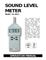
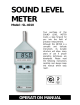
SOUND LEVEL METER
Model : SL-4112
Y
our purchase of this
SOUND LEVEL METER
marks a step forward for
you into the field o
f
precision measurement.
A
lthough this METER is a
complex and delicate
instrument, its durable
structure will allow many
years of use if proper
operating techniques are
developed. Please read
the following instructions
carefully and always keep
this manual within easy
reach.
OPERATION MANUAL

TABLE
OF
CONTENTS
1. FEATURES...............................................................1
2. SPECIFICATIONS.....................................................2
2-1 Electrical specification for Sound level meter...............2
2-2 Electrical specification for Type K/J thermometer........
.
4
2-3 General specification.................................................4
2-4 Electrical specifications for optional probe EM-900P.....5
3. FRONT PANEL DESCRIPTION....................................8
3-1 Microphone.............................................................
.
8
3-2 Display....................................................................8
3-3 Power Button ( Send Button )...................................8
3-4 Hold Button ( ESC Button ) ......................................8
3-5 REC/Max. Min. Button.............................................. 8
3-6 Mode Button ( Lo
gg
er Button, Enter Button ) ...........
.
8
3-7 A/C Wei
g
htin
g
Button ( / Button )......................
.
℃℉ 8
3-8 F/S Button ( Time Wei
g
htin
g
Button ) /Unit Button...
.
8
3-9 PH Button ( Peak Hold Button ) /Settin
g
Button......... 8
3-10 Temperature input socket........................................8
3-11 EM-900P probe input socket....................................
.
8
3-11A Probe lock switch..................................................8
3-12 Screws for battery cover..........................................8
3-13 Tripod Fix Nut.........................................................8
3-14 Stand.....................................................................8
3-15 Battery compartment / Cover...................................8
3-16 AC Output Socket...................................................
.
8
3-17 Sound Calibration VR...............................................8
3-18 RS232 Computer Interface Socket............................8
3-19 DC 9V Power Adapter Input Socket..........................8

4. MEASURING PROCEDURES.......................................9
4-1 Sound level meter..............................................9
4-2 Type K/J thermometer........................................12
4-3 EM-900P ( Humidity, Anemometer, Light ) ..........13
4-4 Data Logger.......................................................14
5. FURTHER SETTING..................................................15
5-1 Thermometer, type K. type J selection.......................
.
16
5-2 Auto power ON/OFF..................................................16
5-3 Chan
g
e the data lo
gg
er samplin
g
time.......................
.
17
5-4 To show the balance data numbers in the memory.....
.
17
5-5 Clear the existin
g
savin
g
data from the memory.........
.
17
5-6 Code enterin
g
for the further calibration usa
g
e...........18
6. SIGNAL OUTPUT......................................................18
6-1 AC output..........................................................18
6-2 RS232 computer interface...................................18
7. REPLACEMENT of BATTERY......................................20
8 CALIBRATION OF SOUND LEVEL METER...................
.
20
9. HOW TO SEND THE DATA OUT FROM THE METER....21
10. FREQUENCY WEIGHTING CHARACTERISTICS
OF A & C NETWORKS.............................................
22
11. TIME WEIGHTING (FAST & SLOW)
CHARACTERISTICS.................................................
22

1. FEATURES
* Large LCD display, easy to read.
* Frequency and Time weighting meet IEC 61672 class 2.
* A, C frequency weighting networks is selected.
* Time weighting (Fast & Slow) dynamic characteristic
modes.
* 0.5" standard microphone head.
* AC output for system expansion.
* RS232 computer interface.
* Auto range & Manual range selection.
* Available for external calibration adjustment.
* Condenser microphone for high accuracy & long-term
stability.
* Memory function to store the Max. & Min. value.
* Hold and MAX. Hold functions.
* Build in type K and type J thermometer.
* Optional probe ( EM-900P ) for Humidity/Temp.,
Light and Anemometer measurement.
* DC 1.5 V battery ( UM-4, AAA ) X 6 or DC 9V
adapter in.
* Operation key used push button.
* LCD display for low power consumption & clear read-out
even in bright ambient light condition.
* Using the durable, long-lasting components, including a
strong, light weight ABS-plastic housing case.
* Small and light weight design allow one hand operation.
* Patent.
1

2. SPECIFICATIONS
2-1 Electrical specification for Sound level mete
r
Function dB ( A & C frequency wei
g
htin
g
), Time
wei
g
htin
g
( Fast, Slow), Hold, Memory
( Max. & Min. ), Peak hold, AC output,
RS232 output.
Meter default Range set to auto range.
function Frequency weighting set to A weighting.
Time weighting set to fast.
Measurement 30 - 130 dB.
Ran
g
e
Resolution 0.1 dB.
Ran
g
e selector
Auto ran
g
e :
30 to 130 dB.
Manual ran
g
e :
3 ran
g
e, 30 to 80 dB, 50 to 100 dB,
80 to 130 dB, 50 dB on each step,
with over & under ran
g
e indicatin
g
.
Frequency 31.5 to 8,000 Hz.
Microphone type Electric condenser microphone.
Microphone size Out size, 12.7 mm DIA. ( 0.5 inch).
Frequency wei
g
htin
g
Characteristics of A & C.
network
* A weighting :
The characteristic is simulated as
"Human Ear Listing" response.
Typical, if making the environmental
sound level measurement, always
select to A weighting.
* C weighting :
The characteristic is near the "FLAT"
response. Typical, it is suitable for
checking the noise of machinery (Q.C.
check) & knowing the sound pressure
level of the tested equipment.
2

Range selector Manual range: 3 ranges ( 30 to 80 dB,
50 to 100 dB, 80 to 130 dB ).
Auto range: 30 - 130 dB.
Time weighting Fast - t= 200 ms, Slow - t = 500 ms,
( Fast & Slow ) * "Fast" range is simulated the
human ear response time.
* "Slow" range is easy to get the avg.
values of vibration sound level.
* The "Fast" & "Slow" response
range are designed to meet IEC 61672
class 2 requirement.
Calibrator B & K (Bruel & kjaer), MULTIFUCTION
ACOUSTIC CALIBRATOR 4226.
Output Signal
* AC output :
AC 0.5 Vrms correspondin
g
to each
ran
g
e step.
Out put impedance - 600 ohm.
* RS232 output.
Output terminal
Terminal 1 :
RS232 computer interface terminal,
photo couple isolated.
Terminal 2 :
AC output terminal.
Terminal socket size :
3.5 mm dia. phone socket.
Calibration VR Build in external calibration VR, easy to
calibrate on 94 dB level by screw driver.
3

2-2 Electrical specification for
Type K/J thermometer
Sensor Reso- Range Accuracy
Type lution
Type K 0.1 ℃ -50.0 to 1300.0 ℃ ± ( 0.4 % + 0.8 )℃
-50.1 to -199.9 ℃ ± ( 0.4 % + 1 )℃
0.1 ℉ -58.0 to 2372.0 ℉ ± ( 0.4 % + 1.5 )℉
-58.1 to -327.8 ℉ ± ( 0.4 % + 1.8 )℉
Type J 0.1 ℃ -50.0 to 1100.0 ℃ ± ( 0.4 % + 0.8 )℃
-50.1 to -199.9 ℃ ± ( 0.4 % + 1 )℃
0.1 ℉ -58.0 to 2012.0 ℉ ± ( 0.4 % + 1.5 )℉
-58.1 to -327.8 ℉ ± ( 0.4 % + 1.8 )℉
*
Accuracy value is specified for the meter only.
*
Temp. probe ( Type K, TP-01 TP-02A, TP-03. TP-04 ) is the
optional accessories.
2-3 General specification
Display 51 mm x 37 mm LCD (Liquid crystal
display), 5 digits with annunciator.
Operating Temp. 0 to 50 ( 32 to 122 ).℃℉
Operating Humidity Less than 80% RH.
Power Supply DC 1.5 V battery ( UM4, AAA ) x 6 PCs,
or equivalent.
Power Approx. DC 12 mA.
Consumption
Dimension 245 x 68 x 41 mm
( 9.6 x 2.7 x 1.6 inch).
Weight 358 g/0.79 LB (including battery).
Accessory Included Instruction Manual ............... 1 PC.
4

Optional
94 dB Sound Calibrator :
Accessories Model : SC-941. SC-942.
Sound wind shield ball
Model : SB-01
RS232 cable ( isolated RS232 cable ) :
Model : UPCB-02.
USB cable
Model : USB-01
Application windows software :
Model : SW-U801-WIN.
Type K Temperature probe :
Model : TP-01 TP-02A, TP-03. TP-04
2-4 Electrical specifications for
optional probe EM-900
P
Anemometer
A
. Air velocity
Measure
-
Range Resolu- Accuracy
ment tion
m/S 0.4 - 25.0 m/s 0.1 m/s ± (2% + 0.2 m/s)
km/h 1.4 - 90.0 km/h 0.1 km/h ± (2% + 0.8 km/h)
mph 0.9 - 55.9 mile/h 0.1 mile/h ± (2% + 0.4 mile/h)
knot 0.8 - 48.6 knots 0.1 knots ± (2% + 0.4 knots)
FPM 80 - 4930 ft/min 1 ft/min ± (2%+40 ft/min.)
Note:
m/S - meters per second km/h - kilometers per hour
FPM - feet per minute knot - nautical miles per hour
mph - miles per hour (international knot)
B. Temperature
Measuring Range 0 to 50 /32 to 122 ℃℃℉ ℉
Resolution 0.1 /0.1 ℃℉
Accuracy ± 0.8 /1.5 ℃℉
5

Humidity/Temp. meter
A
. Humidity
Measuring Range 0 % to 95 % R.H.
Resolution 0.1 % R.H.
Accuracy 70%RH ≧ ± (3% reading + 1% RH).
< 70%RH ± 3% RH.
B. Temperature
Measuring Range 0 to 50 /32 to 122 ℃℃℉ ℉
Resolution 0.1 /0.1 ℃℉
Accuracy ± 0.8 /1.5 ℃℉
Light meter
Measuring Range LUX 0 to 20,000 LUX.
Ft-cd 0 to 1,860 Ft-cd
Resolution LUX 1 LUX
Ft-cd 0.1 Ft-cd
Accuracy ± ( 5% rdg ± 8 dgt )
Note:
Ft-cd : Feet candle
*
Above specification tests under the environment RF Field
Strength less than 3 V/M & frequency less than 30 MHz only.
6

3. FRONT PANEL DESCRIPTION
7

3-1 Microphone
3-2 Display
3-3 Power Button ( Send Button )
3-4 Hold Button ( ESC Button )
3-5 REC/Max. Min. Button
3-6 Mode Button ( Logger Button, Enter Button )
3-7 A/C Weighting Button ( / Button )℃℉
3-8 F/S Button ( Time Weighting Button ) /Unit Button
3-9 PH Button ( Peak Hold Button ) /Setting Button
3-10 Temperature input socket
3-11 EM-900P probe input socket
3-11A Probe lock switch
3-12 Screws for battery cover
3-13 Tripod Fix Nut
3-14 Stand
3-15 Battery compartment / Cover
3-16 AC Output Socket
3-17 Sound Calibration VR
3-18 RS232 Computer Interface Socket
3-19 DC 9V Power Adapter Input Socket
8

4. MEASURING PROCEDURE
4-1 Sound level mete
r
1)Power on by pressing the " Power On/Off Button " ( 3-3,
Fig. 1 ) , the meter's default function is " Auto range ",
" A frequency weighting " & " Fast time weighting ". The
LCD display will show the unit " A. Fast Auto ".
2)Select " A " or " C " frequency weighting by pressing the
" A/C Button " ( 3-7, Fig. 1 ) .
Note :
a. The characteristic table of A, C weighting, please
ref. page 22.
b. The characteristic of A weighting is simulated as
the " Human Ear Listening " response.
Typically always select the A weighting when makes
environmental sound level measurement.
c. The C weighting characteristic is near the " FLAT "
response. Typically it is suitable for checking the
noise of machinery ( Q.C. check ) & knowing the
real sound level of the tested equipment.
3)Determine proper measuring range by pressing the
" Range Button " ( 3-6, Fig. 1 ).
After power on the default range is " Auto range ".
In the same time the lower right display will show the text
of " Auto ".
Under the auto range, press the " Mode Button " ( 3-6,
Fig. 1 ) more than 2 seconds continuously will enter
to the manual range ( range 1, range 2, range 3 ) and
auto range in sequence. There are still 3 manual ranges
for your choice :
9

Manual range 1 , 30 - 80 dB range :
* Display will show the unit of " 30 - 80 ".
Manual range 2 , 50 - 100 dB range :
* Display will show the unit of " 50 - 100 ".
Manual range 3 , 80 - 130 dB range :
* Display will show the unit of " 80 - 130 ".
4) According to various measuring sound source, select the
Time Weighting ( Fast or Slow ) by pressing the " Time
Weighting Button " ( 3-8, Fig. 1 ).
Note :
a. If select the function of " Fast " time weighting, the
display will show the unit of " Fast ".
b. If select the function of " Slow " time weighting, the
display will show the unit of " Slow ".
5)Hold the instrument in hand and point the microphone at
measured noise source, the sound level value ( dB ) will be
displayed on LCD.
6)Peak Hold
If intend to maintain the Peak Hold value, press
the " PH Button " ( 3-9, Fig. 1 ) and a " PH "
symbol will show on the top LCD display. Press the
" PH Button again to exit the function.
Note :
a. When execute Peak Hold function, the time weighting
will default to " Fast " , the display will show
" FAST " indicator.
b. When make the Peak Hold measurement under
slow varying noise environment, please select the
" Auto range "
10

c. When make the Peak Hold measurement under
pulse noise environment, it should select to the
convenient " manual range "
7)Data Hold
During the measurement, pushing the " Hold Button "
( 3-4, Fig. 1 ) will hold the measured value & the LCD
will indicate " " symbol.
* Push the " Hold Button " again to release the data hold
function.
8)Data Record ( Max., Min. reading )
* The data record function displays the maximum and
minimum readings. To start the DATA RECORD
function, press the " REC Button " ( 3-5, Fig. 1) once.
" REC " symbol will appear on the LCD display.
* With the " REC " symbol on the display :
a)Push the " REC. Button " ( 3-5, Fig. 1 ) once, the
" REC Max " symbol along with the maximum value
will appear on the display.
If intend to delete the maximum value, just press
the " Hold Button " ( 3-4, Fig. 1 ) once a while, then
the display will show the " REC " symbol only &
execute the memory function continuously.
b)Push the " REC. Button " ( 3-5, Fig. 1 ) again, the
" REC Min " symbol along with the minimum value
will appear on the display.
If intend to delete the minimum value, just press
the " Hold Button " ( 3-4, Fig. 1 ) once a while, then
the display will show the " REC " symbol only &
execute the memory function continuously.
11

c) To exit the memory record function, push the
" REC " button at least 2 seconds continuously. The
display will revert back to the current reading.
4-2 Type K/J thermometer
1)Power on by pressing the " Power On/Off Button " ( 3-3,
Fig. 1 ) , the meter's default function is " Sound
level meter with auto range "
Press the " Mode Button " ( 3-6, Fig. 1 ) once will
enter to " Thermometer ( type K, type J )
* Press the " Mode Button " ( 3-6, Fig. 1 ) once again
will revert to " Sound level meter "
2)Under the Thermometer mode, if press the / Button "℃℉
( 3-7, Fig. 1 ) can select the Temp. unit to or , in℃℉
the same time LCD will show the or symbol.℃℉
3)The Thermometer is default to " Type K " function,
if intend to change the " Type K " to " Type J ",
please refer the
5-1 Thermometer, type K. type J selection, page 16.
4)Connect the plug of the Temp. probe ( optional type K
probe, TP-01, TP-02A, TP-03, TP-04 ) into the
" Temperature input socket " ( 3-10, Fig. 1 )
* When insert the probe plug into the temp. input
socket should take care to observe the correct
polarity.
5)Data Hold
Same as page 11
6)Data Record ( Max., Min. reading )
Same as page 11
12

4-3 EM-900P ( Humidity, Anemometer, Light )
1)Plug the optional probe EM-900P's plug into the " Probe
Input Socket " ( 3-11, Fig. 1 ).
Slide " Probe lock switch " ( 3-11A, Fig. 1 ) to the " 1 "
position.
2)Power on by pressing the " Power On/Off Button " ( 3-3,
Fig. 1 ) , the meter's default function is " Sound
level meter with auto range "
Press the " Mode Button " ( 3-6, Fig. 1 ) once will
enter to following mode in sequence.
Thermometer ( type K, type J )
Anemometer with Temp.
Humidity with Temp.
Light meter
3)After already select the desiring mode, release the
Mode Button ".
Press the / Button " ( 3-7, Fig. 1 ) can select the℃℉
Temp. unit to or , in the same time LCD will show℃℉
the or symbol.℃℉
Press the " Unit Button " once can select the display unit
for each mode.
Anemometer unit : m/S, Km/h, FPM, knot, mph.
Light unit : Lux, Ft-cd.
4)Data Hold
Same as page 11
5)Data Record ( Max., Min. reading )
Same as page 11
13

4-4 Data Logger
The data logger function can save 1,600-point measuring
data.
The data logger procedures are following :
a)Press the " REC. Button " ( 3-5, Fig. 1 ) once to start
the Data record function and there will be a " REC. "
symbol on the display.
b)Auto Data Logger ( Sampling time should select
to 1, 2, 5, 10, 30, 60, 600, 1800 or 3600 seconds )
Press the " Logger button " ( 3-6, Fig. 1 ) once to start
the Data Logger function. The " REC " symbol will flash
per 1.5 second when save the data into the memory.
Now the Date Logger function is executed.
Manual Data Logger ( Sampling time should set
to 0 second )
Press the " Logger Button " ( 3-6, Fig. 1 ) once will
save the data one time into the memory, at the
same time the symbol " REC " will flash once and
the beeper will sound.
Memory full
When execute the data logger function, if the upper
display show " FULL " with flashing, it indicate the
memory data already over 1,600 no. and the
memory is full.
14

c) During the Data Logger function is executed, press the
" Logger Button " ( 3-6, Fig. 1 ) once will stop the
data logger function, the " REC. " symbol will stop to
flash.
If press the " Logger Button " ( 3-6, Fig. 1 ) once again
will continuous the Data Logger function.
Note :
1)
If intend to change the data logger sampling time, please
refer section 5-3, page 17.
2)
If intend to know the space of balance data numbers into the
memory IC, please refer section 5-4, page 17.
3)
If intend to clear the saving data from the memory please
refer section 5-5, page 17.
5. ADVANCED SETTING
PROCEDURES
Before executing Advanced Setting Procedures,
exit the " Hold function " and the Record "
function first.
* Press " Setting Button " continuously at
least 5 seconds to enter the setting function.
* After already set the desiring value ( function ),
press the " Enter button " to save with default.
* Press the " Unit button " to the next setting
function.
* Press the " Button Button " to the next setting▲▼
function.
* Press the " Esc button " to escape the setting
procedures.
15

a. Hold the " Setting Button " ( 3-9, Fig. 1 ) at least five
seconds will enter the Advanced Setting Procedures.
b. One by one to press the " Unit Button " ( 3-8, Fig. 1 )
once a while to select the main setting function in sequence
and show the text the lower display as :
K...........
.
Change thermocouple type to type K or type J
OFF....... Auto power ON/OFF management
SP-t...... Change the data logger sampling time
SPC.......
.
To show the balance data numbers in the memory
CLr........
.
Clear the existing saving data from the memory
Code.....
.
Code entering for the further calibration usage
5-1 Change thermocouple type to K or J
Change " thermocouple type to K or J " only available
for Type K/J Thermometer
a. Use " button " ( 3-7, Fig. 1 ) button " ( 3-9, Fig.▲▼
1 ) to select " K " or " J ".
b. After select the desiring value ( K or J ), press the
" Enter button " ( 3-6, Fig. 1 ) to save the data with
default.
5-2 Auto power On/Off
( Lower display show " OFF " )
a. Use " button " ( 3-7, Fig. 1 ) button " ( 3-9, Fig. 1 )▲▼
to select " YES " or " no ".
* YES : Auto power off.
* no : Auto power disable.
b. After select the desiring function ( YES or no ), press the
" Enter button " ( 3-6, Fig. 1 ) to save the function with
default.
16

5-3 Change the data logger sampling time
( Lower display show " SP-t " )
a. Use " button " ( 3-7, Fig. 1 ) button " ( 3-9, Fig. 1 ) ▲▼
to select data logger sampling time to
0, 1, 2, 5, 10, 30, 60, 600, 1800, 3600 seconds
b. After the sampling time value is determined, press the
Enter button " ( 3-6, Fig. 1 ) to save the sampling
time with default.
Note :
Set the sampling time to 0 second is used
for the manual Data Logger function.
5-4 To show the balance data numbers in the memory
( Lower display show " SPC " )
The display will show the balance data no. that exist
into the memory ( allow memorize data no. ).
5-5 Clear the existing saving data from the memory
( Lower display show " CLr " )
a. Use " button " ( 3-7, Fig. 1 ) button " ( 3-9, Fig. 1 )▲▼
to select " YES " or " no ".
* YES : It will execute the memory clear function..
* no : It will be not to clear the memory.
b. If select " YES ", press the " Enter button " ( 3-6, Fig. 1 )
the beeper will sound three sounds for warning,
if really intend to clear the memory, then press the
" Enter button " again.
17
/