Page is loading ...

Operator’s Manual
IMPORTANT: Read this manual carefully. It contains information about your
safety and the safety of others. Also become familiar with the controls and
their proper use before you operate the product.
FORM NO. 3319–775
44” or 52” SIDE
DISCHARGE
BAGGER
for
Proline Mid–Size Mowers
Model No. 30128 – 890001 & Up

Printed in USA
Introduction
We want you to be completely satisfied with your
new product, so feel free to contact your local
Authorized Service Dealer for help with service,
genuine replacement parts, or other information you
may require.
Whenever you contact your Authorized Service
Dealer or the factory, always know the model and
serial numbers of your product. These numbers will
help the Service Dealer or Service Representative
provide exact information about your specific
product. You will find the model and serial number
plate located in a unique place on the product as
shown below
.
1
1. Model
and Serial Number Plate
For your convenience, write the product model and
serial numbers in the space below.
Model No:
Serial No.
The warning system in this manual identifies
potential hazards and has special safety messages that
help you and others avoid personal injury, even death.
DANGER, WARNING and CAUTION are signal
words used to identify the level of hazard. However,
regardless of the hazard, be extremely careful.
DANGER signals an extreme hazard that will cause
serious injury or death if the recommended
precautions are not followed.
WARNING signals a hazard that may cause serious
injury or death if the recommended precautions are
not followed.
CAUTION signals a hazard that may cause minor or
moderate injury if the recommended precautions are
not followed.
Two other words are also used to highlight
information. “Important” calls attention to special
mechanical information and “Note” emphasizes
general information worthy of special attention.
The left and right side of the machine is determined
by sitting on the seat in the normal operator’s
position.

1
Contents
Page
Installation 2.
. . . . . . . . . . . . . . . . . . . . . . . . . . . .
Loose Parts 2
. . . . . . . . . . . . . . . . . . . . . . . . .
Installing the Bagger 3
. . . . . . . . . . . . . . . . .
Removing the Bagger 7
. . . . . . . . . . . . . . . . .
Operation 8
. . . . . . . . . . . . . . . . . . . . . . . . . . . . . .
Emptying the Grass Bag 8
. . . . . . . . . . . . . .
Clearing Obstructions from the Bagger 8
. . .
Operating and Bagging Tips 8
. . . . . . . . . . .
Page
Maintenance 9
. . . . . . . . . . . . . . . . . . . . . . . . . . . .
Inspecting the Bagger 9
. . . . . . . . . . . . . . . . .
Inspecting the Mower Blades
9
. . . . . . . . . . .
Caring for the Grass Bag 9
. . . . . . . . . . . . . .
Cleaning the Bagger
9
. . . . . . . . . . . . . . . . . .
Storing the Bagger 9
. . . . . . . . . . . . . . . . . . .

2
Installation
Loose
Parts
DESCRIPTION QTY. USE
Baffle
(18”–for use on 44” deck)
Baf
fle (24”–for use on 52” deck)
Screw (5/16” x 3/4”)
1
1
2
Install baf
fle
Seal T
emplate–44” (for use with 44” deck)
Seal T
emplate–52” (for use with 52” deck)
Back Panel
1
1
1
Cut rubber extension
Mounting Beam
Retainer Bolt
Flange Nut (3/8”–16)
2
4
4
Install mounting beams
Curved Bolt
Washer (3/8”)
Bolt (3/8” x 2 1/2”)
Locknut (3/8”–16)
2
6
2
4
Install mounting assembly on a 44” deck
Bolt (3/8” x 2 1/2”)
Washer (3/8”)
Bolt (3/8” x 4 1/2”)
Locknut (3/8”–16)
2
8
2
4
Install mounting assembly on a 52” deck
Lockup Rod
Bolt (5/16” x 3/4”)
Flange Nut (5/16”–18)
1
2
2
Install lockup rod
Grass Bag and T
ray
Front Bag Support T
ube
Rear Bag Support T
ube
T
russ Head Screw (5/16” 3/4”)
Flange Nut (5/16”–18)
1
1
1
10
10
Install grass bag and tray

Installation
3
Installing
the Bagger
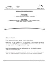
Installing the Baffles
Note: For a 44” deck, use the 18” baffle. For
a 52” deck, use the 24” baffle.
1. Position the appropriate baffle inside the cutting
deck opening so the end is aligned with the edge
of the deck opening and is against the front wall
and ceiling in the storage position (Fig. 1)
1
2
m–3053
Figure 1
1 Baffle
in Bagging Position
2 Baf
fle in Storage Position
2. Using the baffle as a template, mark and drill
two 11/32” holes in the mower deck.
3. Secure the end of the baffle farthest from the
opening with a 5/16” x 3/4” screw.
4. Pivot the end nearest the opening until there is a
distance of 2 3/4” between the baffle and the
front wall of the deck.
5. Using the baffle as a template, mark and drill an
11/32” hole in the mower deck.
6. Secure the end of the baffle closest to the
opening in the bagging position with a 5/16” x
3/4” screw (Fig. 1).
Note: The unused hole is used to mount the
baffle when the mower is not being
used with the bagger.
7. Ensure that both screws are tight.
Trim the Rubber Extension
Note: For a 44” deck, use the template
marked ”Seal Template–44” Deck”.
For a 52” deck, use the template
marked ”Seal T
emplate–52” Deck”.
1. Place the appropriate template against the metal
retaining strips on the outside of the rubber
extension (Fig. 2).
2. Cut the rubber extension along the bottom edge
of the template (Fig. 2).
m–3054
5
4
3
2
1
Figure 2
1 Template
2 Retaining
Strips
3
Rubber Extension
4
Back Panel
5 Cut

Installation
4
Attaching the Mounting Beams to the
Back Panel
1. Secure the mounting beams to the back panel
using four retainer bolts and four 3/8”–16 flange
nuts (Fig. 3).
m–3055
4
1
2
3
Figure 3
1 Back
Panel
2
Mounting Beams
3
Retainer Bolts
4
3/8”–16 Flange Nut
Note: The back panel can be mounted onto
the mounting beams in a range of
vertical positions. When fully
assembled, the back panel should be
adjusted so that the grass bag tray is
positioned slightly below the mower
deck.
Preparing the Cutting Deck and Carrier
Frames for Installation
1. Position the back panel and mounting beam
assembly onto the cutting deck and carrier frame
(Fig. 4). The rubber extension should be
touching the back edge of the discharge opening
(Fig. 5).
m–3056
2
2
1
1
Figure 4
1 Mounting
Holes for 44”
Deck
2
Mounting Holes for 52”
Deck
m–3057
1
2
Figure
5
1 Rubber
Extension
2
Back Edge of Discharge
Opening
2. Using each mounting beam as a template, locate
and drill four 1/2” diameter holes in the carrier
frame, if no holes already exist.

Installation
5
Installing the Mounting Assembly on a
44” Deck
Note: If you are installing the bagger on a
52” deck, skip this section.
1. Insert the flat end of the curved screw into one of
the holes in the carrier frame for the rear
mounting beam (Fig. 6).
2. Insert the treaded end of the curved bolt through
the appropriate hole in the rear mounting beam
and secure it with a 3/8” washer and 3/8”–16
locknut (Fig. 6).
3. Repeat steps 1 and 2 for the other hole in the rear
mounting beam.
m–3058
2
4
1
3
Figure 6
1 Rear
Mounting Beam
2
Curved Bolt
3
3/8” W
asher and 3/8”–16
Locknut
4
Carrier Frame
4. Secure the front mounting beam to the carrier
frame with two 3/8” x 2 1/2” bolts, four 3/8”
washers, and two 3/8” locknuts.
Note: The washers should be positioned on
top of the beam and under the carrier
frame.
Installing the Mounting Assembly on a
52” Deck
Note: If you are installing the bagger on a
44” deck, skip this section.
1. Secure the rear mounting beam to the carrier
frame with two 3/8” x 4 1/2” bolts, four 3/8”
washers, and two 3/8” locknuts.
Note: The washers should be positioned on
top of the beam and under the carrier
frame.
2. Secure the front mounting beam to the carrier
frame with two 3/8” x 2 1/2” bolts, four 3/8”
washers, and two 3/8” locknuts.
Note: The washers should be positioned on
top of the beam and under the carrier
frame.
Installing the Lockup Rod
1. Measure 7” (on a 44” deck) or 7 1/4” (on a 52”
deck) from the edge of the deflector and make a
mark parallel to the edge (Fig. 7).
m–3059
1
2
3
Figure 7
1 Lockup
Rod
2
Deflector Shield
3
7” (44” Deck) or 7 1/4”
(52” Deck)
2. Position the outside mounting hole on the lockup
rod on the line you drew.

Installation
6
3. Raise the deflector and move the lockout rod
back and forth along the course of the line you
drew on the deflector until the rod is centered in
the back panel slot (Fig. 8).
m–3060
1
2
Figure 8
1 Lockup
Rod
2
Lockup Latch
4. Using the lockup rod as a template, mark and
drill two 11/32” diameter holes in the deflector.
5. Secure the lockup rod to the deflector using two
5/16” x 3/4” bolts and two 5/16”–18 flange nuts.
Note: The flange nuts should be on top of the
deflector.
Assembling and Installing the Grass Bag
1. Position the rear bag support tube ends between
the bag rods and the bag tray (Fig. 9).
3
m–3061
2
1
Figure 9
1 Grass
Bag T
ray
2
Front Bag Support T
ube
3
Rear Bag Support T
ube
2. Secure the front bag support tube to the grass
bag tray using six 5/16” x 3/4” truss head screws
and six 5/16”–18 flange nuts.
3. Secure the rear bag support tube to the grass bag
tray using four 5/16” x 3/4” truss head screws
and four 5/16–18 flange nuts.
Note: Use only the bottom two mounting
holes on each side of the rear bag
support tube to secure it to the tray.
4. Move the lockup rod into the slot in the back
panel.
5. Hook the front bag support tube into the lip on
the top of the back panel and lower the bag tray
against the back panel.
6. Hook the lockup latch (Fig. 8) on the bag tube.
7. Adjust the back panel height by sliding the
retainer bolts up or down in the slots in the
mounting beams (Fig. 3) so that the bag tray is
slightly below the bottom of the deck.

Installation
7
Note: This adjustment may need to be made
whenever you adjust the mower height
of cut.
Removing
the Bagger
POTENTIAL
HAZARD
• Sometimes people are tempted to operate
the mower without the grass deflector or
entire bagger in place. This exposes you
and others to thrown debris and blade
contact.
WHAT CAN HAPPEN
• You and others may die or be injured
severely if you are hit by thrown debris or
cut by the blade.
HOW TO AV
OID THE HAZARD
• Always operate the mower with the
complete grass bagger mounted in place or
use the mower to side discharge, making
sure that the grass deflector is in the down
position.
1. Remove the grass bag from the back panel.
2. Remove the bolts, washers, and nuts securing the
mounting beams to the carrier frame, remove the
mounting assembly
, and re–thread the bolts,
washers, and nuts into the mounting beams
(Fig. 4 and Fig. 6).
3. Remove screws and nuts securing the lockup rod
and remove the lockup rod. Replace the screws
and nuts into the holes in the deflector.
4. Remove the baffle screw closest to the opening
in the deck (Fig. 1).
5. Pivot the baffle to the storage position and
secure it with the screw (Fig 1).
6. Store all bagger parts in a convenient place.

8
Operation
To Avoid Personal Injury:
• Become familiar with all operating and
safety instructions in the operator’s manual
for your mower before using this
attachment.
• Never do maintenance or repairs while the
engine is running.
Emptying
the Grass Bag
1. Disengage the power take off (PTO) to stop the
mower blades and release the traction drive or
shift to NEUTRAL as applicable for your
mower.
2. Remove and empty the grass bag.
3. Reinstall the grass bag and resume operation.
Clearing
Obstructions from
the Bagger
1. Disengage the power take off (PTO) to stop the
mower blades and release the traction drive or
shift to NEUTRAL as applicable for your
mower.
2. Remove the grass bag and empty it if full.
3. Carefully remove and clear the obstruction from
the mower.
4. Reinstall the grass bag and resume operation.
Operating
and Bagging T
ips
1. Remember that the mower is wider with the
bagger installed. By turning too sharply in
confined places you may damage the bagger.
2. Do not trim with the right side of the mower
because you could damage the bagger.
3. When mowing rough or uncertain, use care to
avoid damaging the bagger.
4. Air flow is required to cut grass and propel it
into the bag. Setting the height–of–cut too low,
especially in heavy or long grass can restrict the
air flow and plug the mower or bagger.
To avoid plugging, double–cut the grass, first at
a high height–of–cut and then lower the mower
to the desired setting. Also, try to leave one side
of the mower out of the uncut grass, allowing air
to be drawn into the mower housing.

9
Maintenance
Inspecting
the Bagger
Inspect the bagger after the first ten hours of
operation and monthly thereafter.
1. Check the grass bag, back panel, and lockup rod
for damage. Replace any damaged parts.
POTENTIAL HAZARD
• The grass bag material may tear, wear, and
eventually deteriorate.
WHAT CAN HAPPEN
• You or bystanders could be severely injured
by flying debris or thrown objects that pass
through a worn or deteriorated grass bag.
HOW TO AV
OID THE HAZARD
• Frequently check the grass bag for holes,
wear, and other deterioration. Do not wash
the grass bag. If the bag has deteriorated,
install a new grass bag.
2. Tighten all nuts bolts and screws.
Inspecting
the Mower Blades
1. Inspect the mower blades regularly and
whenever a blade strikes a foreign object.
2. If blades are badly worn or damaged, install new
blades. Refer to your mower operator’
s manual
for complete blade maintenance.
Caring
for the Grass Bag
1. Do not wash the grass bag.
2. To prevent rapid deterioration of bag material,
store the bag so it drys completely after each use.
POTENTIAL HAZARD
• If you store grass clippings in the grass bag,
under the right conditions, spontaneous
combustion (a fire-generating process that
occurs without an external source of
ignition) could occur.
WHAT CAN HAPPEN
• If a fire occurs, property could be damaged
and/or someone could be injured.
HOW TO AV
OID THE HAZARD
• The cloth grass bag is not a storage
container. Never store grass clippings and
debris in the grass bag.
Cleaning
the Bagger
1. Frequently clean the inside and outside of the
back panel and the mower deck, using water
sprayed from a hose. Use a mild automotive
detergent to remove stubborn dirt. Do not wash
the grass bag.
2. Ensure you remove matted grass from all parts.
3. After washing let all parts dry thoroughly.
Storing
the Bagger
1. Clean the bagger (refer to Cleaning the Bagger,
page 9).
2. Inspect the bagger for damage (refer to
Inspecting the Bagger, page 9).
3. Ensure the grass bag is empty and dry.
4. Store the bagger in a clean, dry place, out of
direct sunlight. This extends the life of the
bagger. If you must store the bagger outside,
cover it with a weatherproof cover.

/