Page is loading ...

WL270
OPERATING, INSTALLATION, AND SERVICE MANUAL
Waterlogic Commercial Products, LLC
11710 Stonegate Circle
Omaha, NE 68164
(800) 288-1891
www.waterlogic.us

WL270 OPERATING, INSTALLATION, AND SERVICE MANUAL
Congratulations on your choice of the Waterlogic WL270 water treatment system. The WL270
model dispenses cold, ambient and hot. Every WL270 includes:
Bio-Cote® Anti-Microbial Protection
Advanced In-Tank Ultraviolet (UV) Purification
The Waterlogic WL270 provides exceptional quality and great tasting water with every use.
TABLE OF CONTENTS
• Features and Benefits ................................................................. 3
• Certifications ............................................................................... 4
• Introduction and Safety Alert Symbols ....................................... 5
• Safety Precautions ...................................................................... 6
• Model and Part Designations ...................................................... 7
• Specifications .............................................................................. 7
• Operating Instructions ................................................................ 8
• Water Flow Diagram ................................................................... 9
• Pre-Installation Procedures ...................................................... 10
• Draining Procedures.................................................................. 16
• Installation Procedures ............................................................. 17
• Service Requirements ............................................................... 20
• Replacement Components ....................................................... 21
• Hot Tank Descaling Instructions ............................................... 22
• Resetting the Overload or High Limit Safety ............................ 24
• Layout Parts Drawings and Parts Lists …………………… ............... 26
• Hot and Cold Tank Assembly Drawings and Parts Lists ………… 28
• Faucet and Front Hatch Drawing and Part List…………………… ... 29
• Reservoir Assembly Drawing and Part List…………………… ......... 30
• Electrical Diagram ..................................................................... 32
• Fault Codes and Troubleshooting ............................................. 33
• Warranty .................................................................................. 46
WL270 Operating, Installation, and Service Manual Page 2 - Revision: 4-7-2015

WL270 FEATURES AND BENEFITS
Cold, Ambient, and Hot Water
The WL270 unit comes standard with Ambient, Cold and Hot Selections to meet a wide range of
customer demands. Cold Water temperature is adjustable.
High Volume Storage and Water Capacity
The WL270 unit has 4 liters of Cold Water Capacity, 1.6 Liters of Hot Water Capacity and 11.4 Liters
of Reservoir Capacity.
BioCote®Anti-Microbial Protection
Plastic surfaces surrounding dispensing areas and drip tray are infused with an
exclusive silver additive called BioCote®. Silver is a natural anti-microbial that
inhibits the growth of microorganisms providing additional surface protection.
Large Dispense Area with Recessed Faucet
9.0 inch dispense height with BioCote® recessed faucet to protect from cross-contamination.
Leak Detection
The WL270 unit is supplied with a Sensor in the Leak Tray that halts water supply to prevent
overflow.
In-Tank UV Purification
Industry leading In-Tank UV Purification prevents the growth of bio-film within the Stainless Steel
Cold Tank.
WL270 Operating, Installation, and Service Manual Page 3 - Revision: 4-7-2015

WL270 CERTIFICATIONS
Waterlogic water treatment systems have been tested, and certified to rigorous NSF and UL
Standards. We believe that performance testing and certifications validate Waterlogic as a world-
leader in water treatment systems.
WL270 Certifications Include
UL399 – Certified Drinking Water Cooler
Intertek Labs (ETL) Certified the WL270 to ANSI/UL 399 Standard for Drinking Water
Coolers.
BPA Free - Waterlogic tests for BPA and declares that all of its products are Bisphenol-A
FREE and contain no harmful BPA plastics.
NSF/ANSI-61 – Certified Drinking Water System Components
The WL-270 has been tested and certified by The Water Quality Association (WQA) to
NSF/ANSI-61, Section 9.
Waterlogic manufacturing is certified to ISO 9001 – Quality Management
Systems (certified by Moody International). ISO 9001 is the
internationally accepted standard for well managed organizations that
have adopted the key quality management principles to its operations to
bring consistent quality products and a culture of continuous
improvement.
Safe Drinking Water Act
Waterlogic water treatment systems conform to the Safe Drinking Water Act (SWDA) “lead-free”
amendment effective January 4, 2014.
WL270 Operating, Installation, and Service Manual Page 4 - Revision: 4-7-2015

INTRODUCTION
Carefully read and follow all instructions to ensure proper and efficient operation of your WL270.
Contact Waterlogic or an Authorized Waterlogic Dealer if you have any questions.
Waterlogic and Authorized Waterlogic Dealers employ trained service personnel who are
experienced in the installation, function and repair of Waterlogic equipment. This publication is
written for use by these qualified individuals. Waterlogic encourages users to learn about products,
however, we believe that product knowledge and service is best obtained by consulting Waterlogic
or an Authorized Waterlogic Dealer.
Waterlogic water treatment systems should be combined with selected water treatment
components to create a system specifically tailored for each application by trained and qualified
personnel.
Products manufactured and marketed by Waterlogic and its affiliates are protected by patents
issued or pending in the United States and other countries.
Waterlogic reserves the right to change the specifications referred to in this literature at any time,
without prior notice. Changes or modifications not expressly approved by Waterlogic could void the
warranty and user’s authority to operate the equipment.
SAFETY ALERT SYMBOLS
Read and follow all safety information carefully. The signal words used in this manual are selected as
shown below and based on an assessment of the degree of potential injury or damage (severe or
minor) and the occurrence of injury (definitely occurs or has the potential to occur) when the
warning is ignored:
DANGER!
Indicates a situation which, when not avoided, results in death or severe injury.
WARNING!
Indicates a situation which, when not avoided, has the potential to result in death or severe
injury; and/or severe property damage.
CAUTION!
Indicates a situation which, when not avoided, results or has the potential to result in minor
injury; and/or minor property damage.
WL270 Operating, Installation, and Service Manual Page 5 - Revision: 4-7-2015

SAFETY PRECAUTIONS
Basic safety precautions should be followed, including the following:
DANGER! If incorrectly installed, operated or maintained, this product can cause death or
severe injury. Those who install, operate, or maintain this product should be trained in its proper use,
warned of its dangers, and should read the entire manual before attempting to install, operate, or
maintain this product.
WARNING! Unit is to be used for its intended purpose as described in this manual, and
untrained individuals who use this manual assume the risk of any resulting property damage or
personal injury.
WARNING! HOT WATER. Unit produces Hot Water up to 188
o
F. Water above 125
o
F can cause
severe burns or scalding. Keep unauthorized people and children away from the unit to avoid
accidental dispensing of hot water. Children should not use without supervision.
DANGER! ELECTRICAL SHOCK HAZARD. Always unplug from power supply prior to servicing
equipment to prevent electrical shock.
WARNING! This system to be used for water only and is not intended for use where water is
microbiologically unsafe or with water of unknown quality without adequate disinfection before or
after the system. The system is designed for the supplemental bactericidal treatment of either
treated and disinfected public drinking water, or other drinking water, which has been tested and
deemed acceptable for human consumption by the state or local health agency having jurisdiction.
The system is designed to reduce normally occurring non-pathogenic or nuisance microorganisms
only. System is not intended for treatment of contaminated water.
WARNING! Dispenser Could Tip or Fall causing serious injury. Always install unit on a firm, flat,
and level surface and secure the WL270 to the base cabinet with the screw provided to lock the
components together. Never place heavy items on top of unit and never climb, stand, or hang on unit
or storage cabinet to prevent injury and damage.
CAUTION! INDOOR USE ONLY. Do not install outdoors or where unit is in direct sunlight. Do not
install where ambient temperature goes below 50F or above 97F. Avoid high humidity and moisture.
Product life and performance will be impacted and warranty could be voided.
WL270 Operating, Installation, and Service Manual Page 6 - Revision: 4-7-2015

MODEL/PART DESIGNATIONS
BRAND NAME DESCRIPTION
MODEL -
PART NUMBER
WL270
Waterlogic WL270 – Cold, Ambient and Hot 19-GU-SB
F-1001-FS-HCA-UT-BS-INN
SPECIFICATIONS
ITEM WL270
Water Connection ¼” Quick Connect
Cold Water Temperature
Cold Water Temperature – Factory Set Point 41° - 5°C
(Adjustable) 34° - 54° F. (1.1° - 12.2°C)
Hot Water Temperature 185° F (85°C)
Hot Water Manual Reset
Overload
207° F (97°C)
Recommended Service
Pressure
40-60 psi (275-414 kPa) – Use Pressure Regulator
Maximum Service Pressure 100 psi (689 kPa) – Use Pressure Regulator
Rated Service Flow 0.5 gallons per minute (1.89 Lpm)
Environmental Temperature
35° - 100°F (2° - 37°C)
UV Lamp 8 Watts
Heater 500 W
Refrigerant Gas R134a, 58 grams, 2.05 ounces
R134a Pressures High (230 psi), Low (90 psi)
SHIPPING SPECIFICATIONS
ITEM WL270
Width/Depth/Height 15.5” x 14.5” x 45.75” (39cm x 37cm x 116 cm)
Weight (dry) 58 pounds (26 kg)
ELECTRICAL SPECIFICATIONS
ELECTRICAL SUPPLY 120V/60Hz, 1PH 15 Amp Service
COMPONENT POWER (approximate) AMP DRAW (approximate)
Heater 528 4.4 Amps
Compressor 216 1.8 Amps
UV Lamp System 24 0.2 Amps
WL270 TOTAL 738 6.4 Amps
WL270 Operating, Installation, and Service Manual Page 7 - Revision: 4-7-2015

OPERATING INSTRUCTIONS
The above picture shows front LCD display and control panel for the Waterlogic WL270.
For Cold Water: Press Green Cold Water Select Button
For Ambient Water: Press Glue Ambient Water Select Button
For Hot Water: Press both hold the Hot Safety Button (right hand side) while holding down the
Red Hot Water Select Button (left hand side)
Selection Indicator Light
WL270 Operating, Installation, and Service Manual Page 8 - Revision: 4-7-2015

WL270 WATER FLOW DIAGRAM
WL270 Operating, Installation, and Service Manual Page 9 - Revision: 4-7-2015

PRE-INSTALLATION PROCEDURES
DANGER! ELECTRICAL SHOCK HAZARD.
Only qualified personnel who have read and understand this entire manual should attempt to
install, or service this unit, failure to do so could result in death or serious injury. DO NOT plug
into an electrical supply until specifically instructed.
WARNING! ALWAYS SANITIZE BEFORE USE.
Sanitize before use to eliminate any potential microbiological contaminates.
Washing of the Internal Plastic Reservoir, Lid and Float
Materials Needed:
• Personal Protective Equipment. Rubber or Nitrile Safety Gloves and Protective Eyewear
• Phillips Screwdriver
• Sanitizer - Household Bleach (5.25% Sodium Hypochlorite) or Citric Acid Based Cleaner
• Unused sponges or paper towels
• Dish Soap
• Clean water
1. Unpack the Waterlogic WL270 and check exterior for damage.
CAUTION! ALWAYS WASH THE INTERNAL PLASTIC RESERVOIR, LID AND FLOATS PRIOR TO
INSTALLATION.
The internal wetted surfaces of the machine have been handled multiple times in the process of
manufacturing. By following the steps below, you will ensure the cleanliness and sterility of the
drinking water. Refer to the flow diagram in this manual prior to washing of the plastic reservoir,
lid and floats.
2. Remove the top cover and lower panel of the WL270. The two screws securing the top cover are
located in each rear corner. The two screws securing the lower front panel are located on the
front, lower sides near the floor. Depress the recessed tabs of the lower front panel (under the
front-end of the machine) and pull outward simultaneously to remove.
WL270 Operating, Installation, and Service Manual Page 10 - Revision: 4-7-2015

3. Completely remove the plastic internal reservoir from the WL270.
3a.
Remove and discard the
clear silicon float
protector from the
electronic float.
3b.
Loosen the water supply
line fitting from the
mechanical float.
3c.
Disconnect the white
plastic electrical
connectors attached
externally to the
electronic float.
3d.
Pull the silicon ¼” vent
line loose from the hot
tank where it attaches
to the plastic reservoir.
4. Scrub the internal surfaces with soapy water using an unused sponge or paper towels.
5. Rinse well with clean water.
6. While avoiding touching the wetted surfaces of the reservoir with your hands, reinstall the
reservoir into the WL270, reversing the removal steps you performed prior.
Sanitizing the machine
Materials Needed:
• Personal Protective Equipment. Rubber or Nitrile Safety Gloves and Protective Eyewear
• Phillips Screwdriver
• Sanitizer - Household Bleach (5.25% Sodium Hypochlorite) or Citric Acid Based Cleaner
• Unused sponges or paper towels
1. Install the hose adaptor fitting that is packed in the accessories bag found in the drip tray onto
the water inlet fitting on the back of the machine.
CAUTION! DO NOT OVERTIGHTEN
2. Install the metal stand-off plate from the accessories bag and install over the water inlet.
Connect a section of the ¼” plastic tubing from the water supply line into the hose adaptor fitting
at the back of the unit.
CAUTION! DO NOT TURN ON THE WATER YET
3d
3a
3c
3b
WL270 Operating, Installation, and Service Manual Page 11 - Revision: 4-7-2015

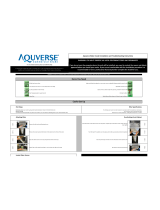
CAUTION! FILTER FLUSH REQUIRED.
WL270’s are not supplied with filters. Filters should be configured to optimize your system.
Filters need to be configured and specified to do the job given the local water conditions, usage,
maintenance schedule, and placement restrictions.
In order for our filters to perform as represented and to provide the best quality water possible, it
is essential that filters be replaced periodically. The frequency of filter changes depends upon your
water quality and your water usage. For example, if there is a lot of sediment and/or particles in
your water, then you will have to change your filters more frequently than a location with little to
no sediment. Be sure to replace your filters whenever you notice a decline in the performance,
whether it is a drop in flow rate and/or pressure or an unusual taste in the water.
3. Flush thoroughly per filter manufacturers’ recommendation with fresh water to drain.
4. Once flushed, install the filters. Following the flow direction on the filters.
NOTE: Filters should not be flushed prior to 24 hours before installation to limit Microbial
Growth.
If you intend to use the Waterlogic RO System, you must remove the filter plate supplied behind
the lower front panel (four screws total). The RO System then mounts on the rails just above the
compressor. Route the RO drain line through the port that is protected by the rubber grommet on
the back of the machine.
5.
Remove the lid to the
internal reservoir of the
WL270.
6.
Pour 2 tablespoons of
Sanitizer - Household
Bleach (5.25% Sodium
Hypochlorite) or Citric
Acid Based Cleaner in
the reservoir.
7.
Replace the reservoir lid.
8.
Unplug (disconnect) one
of the white plastic
electrical connectors
supplying power to the
UV lamp. This step will
prevent interaction
between the sanitizer
and the UV.
WL270 Operating, Installation, and Service Manual Page 12 - Revision: 4-7-2015

Red Compressor/Heater Switch must be in the O=OFF position while the
hot tank is empty. Damage could occur within one minute and the
overload (high limit) will require manual reset if heater is turned on
with an empty hot tank.
9. Turn on the water and plug the WL270 into a power source. Verify the power LED is illuminated
on the front of the unit. The unit should start to fill.
10. Once the reservoir has filled halfway with water, drop two more tablespoons of Sanitizer -
Household Bleach (5.25% Sodium Hypochlorite) or Citric Acid Based Cleaner in the reservoir.
11. Once the reservoir has filled, depress and hold the cold dispense button. This action fills the cold
tank. There will be a pause of up to one minute before the water starts to dispense from the
WL270 faucet.
WARNING! Use Personal Protective Equipment. Gloves and Eye Protection Required. The first
2 or 3 gallons of water will contain concentrated sanitizer. Use extreme care!
12. Once the cold tank is filled (when the water starts streaming into the glass under the faucet,
release the cold dispense button. Depress and verify chlorinated dispenses from the Ambient
faucet.
13. Depress and verify chlorinated water flows from the hot faucet.
14. After water flows from all 3 faucets, turn on the Red Compressor / Heater Switch.
Red Compressor/Heater Switch must be in the I=ON position.
The compressor and hot tank heater systems will begin to operate. The heater LED (not the word
heater, but the LESD above the word “heater”), and the blue chilling LED on the front indication
panel of the machine will be illuminated.
15. Allow the sanitizing solution to remain in the machine until the red heater LED turns off – about
10 minutes.
16. Place a pitcher under the Cold Faucet of the WL270 and dispense 1 gallon of water. Do the same
with the Ambient and Hot Faucets.
WL270 Operating, Installation, and Service Manual Page 13 - Revision: 4-7-2015

17. Turn off the Red Compressor / Heater Switch. Unplug the unit. Switch off the cold and hot drain
caps on the back of the unit. Drain the WL270, replace drain caps.
Red Compressor/Heater Switch must be in the O=OFF position.
18. Reconnect the UV wiring connectors.
19. With the Red Compressor / Heater Switch off, plug the WL270 back into the power source.
Ensure the power LED is illuminated on the front of the WL270. The unit should start to fill.
DANGER! ELECTRICAL SHOCK HAZARD.
Do not plug in unit unless qualified. Only qualified personnel who have read and understand this
entire manual should attempt to install or service this unit.
20. Verify the UV lamp has a faint blue glow underneath the silicon fittings on top of the UV lamp to
ensure it is working. The UV Lamp is directly connected to the electronic float, meaning the lamp
will only be turned on when the unit is filling.
CAUTION! NEVER LOOK DIRECTLY AT A WORKING UV LAMP, EYE DAMAGE WILL OCCUR.
21. Replace the top cover.
22. Once the reservoir has re-filled, verify that all of the sanitizer has been rinsed from the hot, cold
and ambient faucets. Continue dispensing water from the faucets until the water tests chlorine
free. Draining, refilling and dispensing more water from the unit may be necessary to ensure the
water is chlorine free.
23. Turn on the Red Compressor / Heater Switch. This will start the chilling and heating processes.
Red Compressor/Heater Switch must be in the I=ON position.
24. Verify the compressor starts by feeling the head of the compressor for vibration. The
temperature in the cold tank should reach its target temperature within 45 minutes. When the
unit has reached target cold temperature, the compressor will cycle off. The hot tank will take
considerably less time to reach its target temperature of 185° F (85°C).
WL270 Operating, Installation, and Service Manual Page 14 - Revision: 4-7-2015

25. After the cold and hot water temperatures have been reached, turn the Red Heater/Compressor
Switch off.
Red Heater and Compressor Power Switch must be in the O=OFF
position while the hot tank is empty. Damage could occur within one
minute and the overload (high limit) will require manual reset if heater
is turned on with an empty hot tank.
WL270 Operating, Installation, and Service Manual Page 15 - Revision: 4-7-2015

WL270 DRAINING INSTRUCTIONS
Drain the WL270 for transportation.
WARNING! STORE UNIT EMPTY. ALWAYS SANITIZE BEFORE REUSE.
The unit must be completely drained and sealed before storing to avoid stagnation and reduce
microbial growth).
Prior to draining the hot tank, turn off the Red Heater and Compressor Power Switch, and
dispense 2 liters of hot water from the machine. As hot water is dispensed from the faucet of the
unit, colder water will be introduced into the hot tank. Since the red power switch is turned off,
the heater will not energize and heat the incoming tap water. Following this precaution prevents
exposing personnel and equipment (drains, catch basin, etc.) to scalding hot water.
Disable Cold and Hot Tanks
1. Turn off the Red Heater and Compressor Power Switch to disable the heater and compressor.
2. Dispense 2 liters of water through the hot tank to cool the water temperature in the hot tank and
avoid burns.
WARNING! HOT WATER CAN BURN OR SCALD.
Hot water should be dispensed carefully into insulated container to avoid injury.
Turn off Water Supply and Bleed Water Pressure
3. Isolate the unit from feed water by turning off the supply.
4. Dispense cold still water to relieve any pressure built up in the system.
5. Remove the water supply line from the hose adaptor.
Drain the Cold Water Tank and Circuit
6. Remove Hose Adaptor.
7. Remove Drain Caps located on back of unit.
8. After unit drains, replace drain caps.
WL270 Operating, Installation, and Service Manual Page 16 - Revision: 4-7-2015

INSTALLATION PROCEDURES
Safety and Installation Guidelines
Ensure all Local, State, and Federal Laws and Codes including health and safety guidelines are met
when installing Waterlogic Equipment. Only qualified service technicians should attempt
installation and service of Waterlogic Equipment.
WARNING! ELECTRICAL SHOCK HAZARD. Always unplug (isolate from power supply) to prevent
electrical shock except where electrical tests are specified.
WARNING! IMPROPER SUPPLY OR CONNECTION CAN RESULT IS RISK OF SHOCK.
Connect to a 15 amp 120V 60Hz properly grounded outlet (GFI is recommended). Ensure polarity is
correct and always use a 3-prong outlet. Consult a qualified electrician if you have any questions.
WARNING! USE ONLY Waterlogic SUPPLIED POWER CORD. Locate system within 5 feet of
power supply. Never use an extension cord or adapter. Do not use a damaged power cord or plug.
Keep power cord out of heavy traffic areas and away from heat sources. Do not, under any
circumstances, remove ground prong or alter the power cord. Never pull the power plug from the
outlet with a wet hand or allow the plug to get wet. Failure to use the supplied power cord will void
UL Certification and Warranty.
CAUTION! INDOOR USE ONLY. Never expose to direct sunlight, heat sources, or ambient air
temperature above 100°F (37°C) or below 35°F (2°C). Install indoors and keep unit away from
excessive humidity. Never expose to freezing temperatures. Ensure there is adequate clearance
around the unit to allow refrigeration system condenser to dissipate heat. Warmer environments
require more clearance around the unit. Minimum clearance around all surfaces of the machine is 2-
inches. Installs where the ambient temperature exceed 80F, require a minimum of 4-inches clearance
for proper heat dissipation and efficient operation.
CAUTION! USE A WATER PRESSURE REGULATOR. Waterlogic will not be responsible for injury or
damage caused by excessive water pressure. Operating pressure must be 40 psi to 60 psi. Be aware
any of potential pressure surges caused by building/municipal pumping stations.
CAUTION! USE UV STABILIZED SUPPLY LINES. Feed the unit with a potable ambient or cold
water supply only. Feed water over 100° F (37°C) can damage the treatment components. Water
block devices and external leak detectors are strongly recommended. Locate the unit as close to the
water supply and the electrical connections as possible.
WARNING! STORE AND TRANSPORT UNIT EMPTY. ALWAYS SANITIZE BEFORE USE.
The unit must be completely drained and sealed before storing to avoid stagnation and reduce
microbiological contamination (potential bacterial growth). Sanitize before use to eliminate any
potential microbiological contaminates
Pre-installation and sanitization procedures as prescribed in this manual must be performed before
installing the WL270.
Always install indoors and place the Waterlogic WL270 on a firm, flat and stable surface.
WL270 Operating, Installation, and Service Manual Page 17 - Revision: 4-7-2015

1. Attach the water supply line to the 1/4” feed water hose adaptor fitting on the back of the unit.
Waterlogic requires the use of a water pressure regulator. Water feed pressure must be
between 40-60 psi. Turn on the water supply and check for leaks.
2. Check to ensure that the Red Heater and Compressor Power Switch is the
O=OFF position.
NOTE: Switches have internal LED that illuminates when placed in I=ON
position.
3. Connect the power cord to the back of the Waterlogic WL270 and to a 120 Volt supply.
4. Turn on water supply and allow reservoir to fill.
5. Fill the Cold Tank. Hold a container under the dispensing faucet, press and hold the cold
dispensing button until a continuous flow of water is obtained. Once a continuous flow is
obtained, release the dispensing button. Cold tank is now full.
6. Fill the Hot Tank. Hold a container under the
dispensing faucet. Press and hold the Hot Safety
Button followed by the Hot dispensing button until
a continuous flow of water is obtained. Once a
continuous flow is obtained, release the main
dispensing button. Hot tank is now full.
CAUTION! NEVER TURN ON HEATER BEFORE
FILLING HOT TANK.
Red Heater and Compressor Power Switch must be
in the O=OFF position while the hot tank is empty.
Damage could occur within one minute and the
overload (high limit) will require manual reset if
heater is turned on with an empty hot tank.
7. Verify that the UV lamp operates as expected.
WARNING! ULTRAVIOLET RADIATION. Protect your skin and eyes against ultraviolet rays.
Never look directly at an operating UV light. Always disconnect before removal.
8. Move the Waterlogic WL270 into its final operating position. Be sure that a minimum of 2”
clearance is maintained around both the sides and the back of the unit. This is important to allow
proper airflow and heat exchange of refrigeration system.
9. Level unit using the adjustable feet to level if necessary. Never install on incline.
10. Turn the Red Heater and Compressor Power Switch to I=ON position.
11. When the unit has reached its Hot Temp Set Point, the heater will cycle off. When the unit has
reached its Cold Temp Set Point Temperature, the compressor will cycle off.
Hot Safety
Button
Hot Water
Select Button
Press and hold the Hot Safety Button
+ the Hot Water Select Button to
dispense hot water
WL270 Operating, Installation, and Service Manual Page 18 - Revision: 4-7-2015

12. Once the unit is at the target temperature(s), sample the water to ensure water meets
expectations and additional rinsing or adjustment is not required.
13. Check the unit for any leaks. External Leak Protection is always recommended.
WL270 Operating, Installation, and Service Manual Page 19 - Revision: 4-7-2015

SERVICE REQUIREMENTS
WARNING! Read and understand the contents of this manual before attempting to service
WL270. Failure to follow the instructions in this manual could result in death, serious personal
injury, or severe property damage. Only trained and qualified technicians should attempt to
install, maintain, or service Waterlogic Equipment.
1. Visually inspect all electrical and water connections for signs of wear or damage.
DANGER! HIGH VOLTAGE ELECTRICAL HAZARD. Unplug before inspection and service.
2. Waterlogic recommends changing the UV Lamp every 12 months.
NOTE: When replacing the UV lamp the wiring harness must also be
replaced.
NOTE: The Glow Starter shown to the right, may appear blackened
which is normal.
WARNING! ULTRAVIOLET RADIATION. Protect your skin and eyes against ultraviolet rays.
Never look directly at an operating UV light. Disconnect before removing UV Lamp.
CAUTION! UV LAMPS ARE HAZARDOUS. Lamps are considered Hazardous Waste and must
be disposed of accordingly. Refer to Product MSDS sheet for details.
3. Clean the quartz sleeve that surrounds the UV lamp with a non-abrasive cloth, descaling solution,
or ultrasonic bath if needed when changing UV lamps.
CAUTION! UV SYSTEM IS FRAGILE. Never handle the UV lamp or Quartz Sleeve with bare
hands. UV Lamp and quartz sleeve must be free of oils and contaminants to ensure proper
operation. Use a soft non-abrasive cloth to clean.
4. Inspect the Quartz Sleeve O-ring for wear or damage and replace as necessary.
5. Ensure there is adequate (minimum of 2”) clearance around the unit and clean the condenser grill
and compressor fan to provide efficient cooling system operation.
6. Sanitize the cold tank per instructions in the pre-installation procedures.
7. Clean and sanitize external surfaces of the unit. Use soap and water or chemicals that are
compatible with ABS plastic and will not damage or degrade the product surfaces.
8. Remove and clean the Faucet. Replace as needed.
WARNING! SANITIZER MAY CONTAIN HAZARDOUS CHEMICALS. Use of proper personal
protective equipment such as rubber gloves and eye protection is required.
WL270 Operating, Installation, and Service Manual Page 20 - Revision: 4-7-2015
/