Page is loading ...

Waterlogic Commercial Products, LLC
11710 Stonegate Circle
Omaha, NE 68164
(800) 288-1891 www.waterlogic.us
Tech Portal Website: www.techportal.waterlogic.com
WL350
OPERATING, INSTALLATION, AND SERVICE MANUAL

WL350 Operating, Installation, and Service Manual Page 2 – Revision 8-30-2016
WL350 OPERATING, INSTALLATION, AND SERVICE MANUAL
Congratulations on your choice of the Waterlogic WL350 Water Treatment System. The WL350
Water Treatment System model dispenses cold, and hot. Every WL350 Water Treatment System
includes:
High Performance Multi-Stage Filtration
Bio-Cote Anti-Microbial Protection
Firewall Advanced Purification
The Waterlogic WL350 Water Treatment System provides exceptional quality and great tasting
water with every use.
INTRODUCTION
Carefully read and follow all instructions to ensure proper and efficient operation of your WL350
Water Treatment Systems. Contact Waterlogic or an Authorized Waterlogic Dealer if you have any
questions.
Waterlogic and Authorized Waterlogic Dealers employ trained service personnel who are
experienced in the installation, function and repair of Waterlogic equipment. This publication is
written for use by these qualified individuals. Waterlogic encourages users to learn about products,
however, we believe that product knowledge and service is best obtained by consulting Waterlogic
or an Authorized Waterlogic Dealer.
Waterlogic Water Treatment Systems should be combined with selected water treatment
components to create a system specifically tailored for each application by trained and qualified
personnel.
Products manufactured and marketed by Waterlogic and its affiliates are protected by patents
issued or pending in the United States and other countries.
Waterlogic reserves the right to change the specifications referred to in this literature at any time,
without prior notice. Changes or modifications not expressly approved by Waterlogic could void the
warranty and user’s authority to operate the equipment.

WL350 Operating, Installation, and Service Manual Page 3 – Revision 8-30-2016
TABLE OF CONTENTS
USER GUIDE
Safety Alert Symbols ................................................................ 4
Safety Precautions ................................................................... 4
Features and Benefits .............................................................. 7
Certifications ............................................................................ 8
Model Designations and General Specifications ..................... 9
Electrical and Shipping Specifications .................................... 10
Operating Instructions ........................................................... 11
Warranty ............................................................................... 12
SERVICE GUIDE
Service Requirements ............................................................ 13
Hot Tank Principles of Operation ........................................... 14
Heater Circuit – Hot Tank Wiring ........................................... 15
Resetting the Hot Tank Overload (High Limit Safety) ............ 16
Hot Tank Descaling................................................................. 18
Firewall Outlet Solenoid – Reverse Flow Orientation ........... 20
Adjusting Cold Water Set Point ............................................. 21
Programming – Disabling Energy Saving Sleep Mode ........... 22
Programming – Changing Hot Water Mode to Ambient ....... 23
Replacement Components (Consumables) ........................... 24
Countertop Drawings and Parts List…………………… ................ 25
Tower Drawings and Parts List……………………......................... 32
Counter Top Flow Diagram .................................................... 39
Tower Flow Diagram .............................................................. 40
Electrical Schematic ............................................................... 41
INSTALLATION GUIDE
Pre-Installation Procedures ................................................... 42
Countertop Draining Procedure ............................................ 46
Tower Draining Procedure ..................................................... 47
Installation Instructions ......................................................... 48
TROUBLESHOOTING GUIDE
Fault Codes ............................................................................. 50
Power Troubleshooting.......................................................... 53
Dispense Troubleshooting ..................................................... 56
Cold Water Troubleshooting .................................................. 68
Hot Water Troubleshooting ................................................... 69

WL350 Operating, Installation, and Service Manual Page 4 – Revision 8-30-2016
SAFETY ALERT SYMBOLS
Read and follow all safety information carefully. The signal words used in this manual are selected as
shown below and based on an assessment of the degree of potential injury or damage (severe or
minor) and the occurrence of injury (definitely occurs or has the potential to occur) when the
warning is ignored:
DANGER!
Indicates a situation which, when not avoided, results in death or severe injury.
WARNING!
Indicates a situation which, when not avoided, has the potential to result in death or severe
injury; and/or severe property damage.
CAUTION!
Indicates a situation which, when not avoided, results or has the potential to result in minor
injury; and/or minor property damage.
SAFETY PRECAUTIONS
Basic safety precautions should be followed, including the following:
Ensure all local, state, and federal laws and codes including health and safety guidelines are met
when installing Waterlogic Equipment. Only qualified service technicians should attempt
installation and service of Waterlogic Equipment. Always read the entire operating instructions
before using the appliance and save these instructions for future use.
DANGER! ELECTRICAL SHOCK HAZARD. Always use a dedicated and properly grounded outlet.
Unit should be protected by ground-fault circuit interrupter (GFCI) or residual current device (RCD)
having a rated residual operating current not exceeding 30mA. Use only Waterlogic supplied
power cord. Never use extension cords or power strips to connect unit. Do not use if the power
supply cord is damaged. Always unplug from power supply prior to servicing.
WARNING! AUTHORIZED USE ONLY. This appliance is to be used for its intended purpose as
described in this manual, and untrained individuals who use this manual assume the risk of any
resulting property damage or personal injury. This appliance can be used by children aged from 8
years and above and persons with reduced physical, sensory or mental capabilities or lack of
experience and knowledge if they have been given supervision or instruction concerning use of the
appliance in a safe way and understand the hazards involved.
WARNING! SUPERVISE CHILDREN. Keep appliance and cord out of reach of children under the
age of 8years. Children under the age of 8 years must not use or play with the appliance.
WARNING! DO NOT OPERATE IF DAMAGED. Unplug if abnormal case occurs. Contact Waterlogic
or authorized dealer for repair, service, and installation to avoid hazards.
WARNING! HOT WATER. Unit produces Hot Water in excess of 87
o
C (188
o
F). Water above 52
o
C
(125
o
F) can cause severe burns or scalding. Keep unauthorized people and children away from the
unit to avoid accidental dispensing of hot water.

WL350 Operating, Installation, and Service Manual Page 5 – Revision 8-30-2016
WARNING! CONNECT TO POTABLE WATER SUPPLY. This system is to be used for water only and
is not intended for use where water is microbiologically unsafe or with water of unknown quality
without adequate disinfection. System is designed for the supplemental bactericidal treatment of
public drinking water, or other drinking water, which has been tested and deemed acceptable for
human consumption by the state or local health agency having jurisdiction. The system is designed
to reduce normally occurring non-pathogenic or nuisance microorganisms only. System is not
intended for treatment of contaminated water.
WARNING! TIP HAZARD. Dispenser could tip or fall causing serious injury. Always install unit on a
firm, flat, and level surface and secure the WL350 Water Treatment System to the base cabinet
with the screw provided to lock the components together. Secure unit to cabinet, wall, or floor if
needed. Never place heavy items on top of unit and never climb, stand, or hang on unit or storage
cabinet to prevent injury and damage.
WARNING! UNIT IS HEAVY. TWO PERSON LIFT REQUIRED. Transport unit empty and always use
material handling equipment or two people with proper lifting technique to reduce injury risk.
WARNING! STORE AND TRANSPORT UNIT EMPTY. ALWAYS SANITIZE BEFORE USE.
The unit must be completely drained and sealed before storing to avoid stagnation and reduce
microbiological contamination (potential bacterial growth). Sanitize before use to eliminate any
potential microbiological contaminates
CAUTION! INDOOR USE ONLY. Intended for household use only. Never expose to direct sunlight,
heat sources, or ambient air temperature above 37°C (100°F) or below 2°C (35°F). Install indoors
and keep unit away from excessive humidity. Never expose to freezing temperatures. Ensure
there is adequate clearance around the unit to allow refrigeration system condenser to dissipate
heat. Warmer environments require more clearance around the unit. Minimum clearance around
all surfaces of the machine is 2-inches. Installs where the ambient temperature exceeds 27°C
(80°F), require a minimum of 4-inches clearance for proper heat dissipation and efficient
operation.
CAUTION! USE A WATER PRESSURE REGULATOR. Waterlogic will not be responsible for injury or
damage caused by excessive water pressure. Input or feed pressure must be 40 psi to 60 psi. Be
aware of any potential pressure surges caused by building/municipal pumping stations. Water
block devices and external leak detectors are strongly recommended. Locate the unit as close to
the water supply and the electrical connections as possible to minimize risk.
CAUTION! USE PROPER SUPPLY LINES AND FEED WITH POTABLE AMBIENT WATER ONLY.
Feed water over 37°C (100°F) may damage the treatment components. Always use supply lines
with adequate pressure rating and UV resistance. Close water supply valve and contact service
representative if a leak is noticed.
Contact Waterlogic for assistance or help finding an Authorized Service Representative.

WL350 Operating, Installation, and Service Manual Page 6 – Revision 8-30-2016
WARNING! CONNECT TO POTABLE WATER SUPPLY. This system is to be used for water only and
is not intended for use where water is microbiologically unsafe or with water of unknown quality
without adequate disinfection. System is designed for the supplemental bactericidal treatment of
public drinking water, or other drinking water, which has been tested and deemed acceptable for
human consumption by the state or local health agency having jurisdiction. The system is designed
to reduce normally occurring non-pathogenic or nuisance microorganisms only. System is not
intended for treatment of contaminated water.
WARNING! TIP HAZARD. Dispenser could tip or fall causing serious injury. Always install unit on a
firm, flat, and level surface and secure the WL350 Water Treatment System to the base cabinet
with the screw provided to lock the components together. Secure unit to cabinet, wall, or floor if
needed. Never place heavy items on top of unit and never climb, stand, or hang on unit or storage
cabinet to prevent injury and damage.
WARNING! UNIT IS HEAVY. TWO PERSON LIFT REQUIRED. Transport unit empty and always use
material handling equipment or two people with proper lifting technique to reduce injury risk.
WARNING! STORE AND TRANSPORT UNIT EMPTY. ALWAYS SANITIZE BEFORE USE.
The unit must be completely drained and sealed before storing to avoid stagnation and reduce
microbiological contamination (potential bacterial growth). Sanitize before use to eliminate any
potential microbiological contaminates
CAUTION! INDOOR USE ONLY. Intended for household use only. Never expose to direct sunlight,
heat sources, or ambient air temperature above 37°C (100°F) or below 2°C (35°F). Install indoors
and keep unit away from excessive humidity. Never expose to freezing temperatures. Ensure
there is adequate clearance around the unit to allow refrigeration system condenser to dissipate
heat. Warmer environments require more clearance around the unit. Minimum clearance around
all surfaces of the machine is 2-inches. Installs where the ambient temperature exceeds 27°C
(80°F), require a minimum of 4-inches clearance for proper heat dissipation and efficient
operation.
CAUTION! USE A WATER PRESSURE REGULATOR. Waterlogic will not be responsible for injury or
damage caused by excessive water pressure. Input or feed pressure must be 40 psi to 60 psi. Be
aware of any potential pressure surges caused by building/municipal pumping stations. Water
block devices and external leak detectors are strongly recommended. Locate the unit as close to
the water supply and the electrical connections as possible to minimize risk.
CAUTION! USE PROPER SUPPLY LINES AND FEED WITH POTABLE AMBIENT WATER ONLY.
Feed water over 37°C (100°F) may damage the treatment components. Always use supply lines
with adequate pressure rating and UV resistance. Close water supply valve and contact service
representative if a leak is noticed.
Contact Waterlogic for assistance or help finding an Authorized Service Representative.

WL350 Operating, Installation, and Service Manual Page 7 – Revision 8-30-2016
WL350 FEATURES AND BENEFITS
Ambient, Cold and Hot Water
Cold and Hot Selections, which can be changed to Ambient and Cold settings to meet a wide range of
customer demands.
High Volume Storage and Water Capacity
Tower Model has 4 liters (1 gallon) of Cold Water Capacity and 1.6 Liters (.43 gallons) of Hot Water.
Counter Top has 2 liters (½ gallon) of Cold Water Capacity and 1.6 Liters (.43 gallons) of Hot Water.
BioCote®Anti-Microbial Protection
Plastic surfaces surrounding dispensing areas and Drip Tray are infused with an
exclusive silver additive called BioCote®. Silver is a natural anti-microbial that
inhibits the growth of microorganisms providing additional surface protection.
Large Dispense Area with Recessed Faucet
8.5 inch dispense height with BioCote® recessed faucet to protect from cross-contamination.
Leak Detection
WL350 Water Treatment Systems are supplied with a Sensor in the Leak Tray that halts water supply
to prevent overflow and sounds alarm to reduce accident potential.
Child Safeguard
WL350 Water Treatment Systems requires Hot Water selection followed by main dispense for Hot
Water, and defaults back to cold selection after 3 seconds of inactivity to prevent accidental
dispensing of hot water.
Energy Saving Sleep Mode
Energy Saving Sleep Mode can be programmed to turn off heater after 3 hours of inactivity.
Firewall™
Firewall is proprietary technology that places the UV lamp at the point of
dispense. This point of dispense purification keeps the dispense nozzle free
from external contamination as well as purifying the water, making the
freshest water possible.
Auxiliary Port
Auxiliary Port to feed Coffee Machines or other Appliances on Counter Top Models.

WL350 Operating, Installation, and Service Manual Page 8 – Revision 8-30-2016
WL350 CERTIFICATIONS
Waterlogic Water Treatment Systems have been tested, approved, and certified by the world’s top
standards bodies such as NSF and ANSI. These organizations set and regulate national standards. We
believe that performance testing and certifications validate Waterlogic as a world-leader in water
treatment systems.
WL350 Water Treatment System Certifications Include
NSF/ANSI-55 Class A –Ultraviolet Microbiological Water Treatment Systems
Water Quality Association is an international standards organization. Firewall™ Technology
contains our latest, most innovative and patented breakthrough, “The Firewall™”, the most
comprehensive UV purification system for point-of-use water treatment systems ever
developed. The Waterlogic Firewall components has been tested and certified by the Water
Quality Association (WQA) to NSF/ANSI-55 Class A – Ultraviolet Microbiological Water
Treatment Systems, and to NSF/P231 and the USEPA Standard for Microbiological Water
Purifiers.
NSF P231 –Protocol for Microbiological Purifiers
The Public Health and Safety Organization establishes minimum requirements for health and
sanitation characteristics of microbiological water purifiers. The requirements are based on
the recommendations of the U.S. Environmental Protection Agency's Task Force Report.
NSF/ANSI-42 – Chlorine, Taste and Odor Reduction
NSF/ANSI-53 – Lead and Cyst Reduction
The Public Health and Safety Organization establishes minimum requirements for materials,
design, construction, and performance of drinking water treatment units that are designed to
reduce specific aesthetic-related contaminants in public or private water supplies.
UL399 – Certified Drinking Water Cooler
Intertek Labs (ETL) Certified the WL350 Water Treatment System to ANSI/UL 399 Standard for
Drinking Water Coolers.
BPA Free - Waterlogic tests for BPA and declares that all of its products are Bisphenol-A FREE
and contain no harmful BPA plastics.
Energy Star Certified
The WL350 Water Treatment Systems, have been tested and certified to the Energy Star,
a US Environmental Protection Agency (EPA) program that helps our customers save
money and protect our climate through superior energy
efficiency.
Waterlogic is certified to ISO 9001:2008 – Quality Management Systems
(certified by Intertek). ISO 9001 is the internationally accepted standard
for well managed organizations that have adopted the key quality
management principles to its operations to bring consistent quality products and a culture of
continuous improvement.
Safe Drinking Water Act
Waterlogic water treatment systems conform to the Safe Drinking Water Act (SWDA) “lead-free”
amendment effective January 4, 2014.

WL350 Operating, Installation, and Service Manual Page 9 – Revision 8-30-2016
MODEL/PART DESIGNATIONS
BRAND NAME
DESCRIPTION
MODEL – PART NUMBER
WL350 Counter Top
Waterlogic WL350 Counter Top - Cold and Hot
12-CHCMFW3
F-2FW-M-HC-TT-CS-INN
WL350 Tower
Waterlogic WL350 Tower - Cold and Hot
12-CHCFW3
F-2FW-FS-HC-TT-CS-INN
SPECIFICATIONS
ITEM
WL350 Counter Top
WL350 Tower
Water Connection
¼” Quick Connect
Cold Water Temperature
Cold Water Temperature – Factory Set Point 5°C (41°F)
Adjustable to 1.1°- 12.2°C (34° - 54° F)
Hot Water Temperature
85°C (185°F)
Hot Water Manual Reset
Overload
105°C (221°F)
Recommended Incoming
Feed Pressure
40-60 psi (275-414 kPa) – Use Pressure Regulator
Maximum Service Pressure
100 psi (689 kPa) – Use Pressure Regulator
Rated Service Flow Out
1.89 Liters per Minute (0.5 Gallons per Minute) – Firewall Purification
Environmental Temperature
2°- 37°C (35°- 100°F)
UV Lamp
15 Watts
15 Watts
Heater
500 W
Refrigerant Gas
R134a, 40g, 1.41 ounces
R134a, 65g, 2.29 ounces
R134a Pressures
High (230 psi), Low (90 psi)

WL350 Operating, Installation, and Service Manual Page 10 – Revision 8-30-2016
SHIPPING SPECIFICATIONS
ITEM
WL350 Counter Top
WL350 Tower
Width/Depth/Height
34cm x 37cm x 45cm
13.5” x 14.5” x 17.75”
#
34cm x 41cm x 104cm
13.5” x 14.5 x 41”
Weight (dry)
26.3 kg (58 pounds)
30 kg (66 pounds)
ELECTRICAL SPECIFICATIONS
ELECTRICAL SUPPLY
120V/60Hz
15 Amp Service
COMPONENT
POWER (approximate)
AMP DRAW (approximate)
Heater
504
4.2 Amps
Compressor
216
1.8 Amps
UV Lamp System
18
0.15 Amps
WL350 TOTAL
738
6.15 Amps
#WL350 Counter Top is 17.75 in. tall and may not fit between countertops and cabinets - Check installation to ensure adequate clearance.

WL350 Operating, Installation, and Service Manual Page 11 – Revision 8-30-2016
OPERATING INSTRUCTIONS
The above picture shows front LCD display and control panel for the Waterlogic WL350 Water
Treatment System.
For Cold Water: Press Cold Water Select Button followed by the Dispensing Button (within 3
seconds).
For Hot Water: Press Hot Water Select Button followed by the Dispensing Button (within 3
seconds).
NOTE: Default selection mode is Cold Water. Selection will return to default after 3 seconds of
inactivity.
NOTE: Selection indication light will turn Red when the Hot Water Select button is pressed, and will
switch back to the default green within 3 seconds after dispensing the hot water.
Cold Water
Select
Hot Water
Select
Dispensing Button
Temperature Indicator Light

WL350 Operating, Installation, and Service Manual Page 12 – Revision 8-30-2016
WATERLOGIC MANUFACTURED WATER TREATMENT SYSTEM LIMITED WARRANTY
UNITED STATES AND CANADA ONLY
Waterlogic water treatment systems are guaranteed to the original purchaser to be free of defects in
materials and workmanship for a period of three (3) years from the date of purchase, but in no event
longer than forty-eight (48) months from the date of manufacture. Waterlogic Commercial Products,
LLC (“Waterlogic”) based in the U.S.A. and its affiliated companies are not liable for any cost of
removal, installation, transportation, or any other charges which may arise in connection with a
warranty claim.
This warranty does not cover damage or wear to products caused by abnormal operating conditions,
accident, abuse, misuse, unauthorized or improper alteration or repair, damage caused by or
resulting from shipping or accident, damage caused by hot water, freezing, flood, fire, or acts of God.
The effects from chlorine corrosion, scaling and normal wear are specifically excluded from this
warranty. This warranty does not cover products used outside the countries where the unit was
purchased, and does not cover products that were not installed in accordance with Waterlogic printed
installation and operating instructions obtained in training or from www.waterlogic.us. Failure to
follow all instructions for operation and maintenance voids the warranty. This warranty is not
transferable.
To obtain warranty repairs or replacement, you must obtain a Return Authorization from Waterlogic.
To obtain a Return Authorization, you must submit a Return Authorization form with supporting
documentation to Waterlogic for evaluation. The form is available at www.waterlogic.us. Supporting
documentation must include, but is not limited to; proof of purchase, installation date, failure date,
and supporting installation and maintenance data. After you submit a Return Authorization form and
supporting documentation, Waterlogic will determine whether a reasonably apparent defect in
materials or workmanship covered by this limited warranty exists. If Waterlogic determines the
claimed defect is covered by this warranty, Waterlogic will, at its sole discretion, determine whether
to correct the defect or replace the unit, free of charge to you. If Waterlogic determines that the unit
should be returned for warranty service, Waterlogic will approve of return in writing and will issue a
Return Authorization which you must obtain prior to shipping the product. You are responsible for the
cost of freight in to Waterlogic.
Waterlogic and its affiliated companies hereby limit the duration of any and all implied warranties to
a maximum period of three (3) years from the date of purchase including, but not limited to, the
implied warranties of merchantability and fitness for a particular purpose. Some states do not allow
limitations on how long an implied warranty lasts, so the above limitation may not apply to you.
Consequential and incidental damages are not recoverable under this warranty. Some states do not
allow the exclusion or limitation of incidental or consequential damages, so the above limitation or
exclusion may not apply to you.
This warranty gives you specific legal rights and you may also have other rights which may vary from
state to state.
New Warranty Policy issued by Waterlogic Commercial Products LLC, USA - January 10, 2014
Waterlogic Commercials Products LLC Tel: (800) 288-1891
11710 Stonegate Circle Website: waterlogic.us
Omaha, NE 68164

WL350 Operating, Installation, and Service Manual Page 13 – Revision 8-30-2016
SERVICE REQUIREMENTS
WARNING! Read and understand the contents of this manual before attempting to service
WL350 Water Treatment System. Failure to follow the instructions in this manual could
result in death, serious personal injury, or severe property damage. Only trained and
qualified technicians should attempt to install, maintain, or service Waterlogic Equipment.
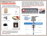
1. Visually inspect all electrical and water connections for signs of wear or damage.
DANGER! HIGH VOLTAGE ELECTRICAL HAZARD. Unplug before inspection and service.
2. Waterlogic recommends changing the UV Lamp every 6 months.
WARNING! ULTRAVIOLET RADIATION. Protect your skin and eyes against ultraviolet rays.
Never look directly at an operating UV light. Disconnect before removing UV Lamp.
CAUTION! UV LAMPS ARE HAZARDOUS. Lamps are considered Hazardous Waste and must
be disposed of accordingly. Refer to Product MSDS sheet for details.
3. Clean the Spiral Quartz Sleeve that surrounds the UV Lamp with a non-abrasive cloth, descaling
solution, or ultrasonic bath if needed when changing UV Lamps.
CAUTION! UV SYSTEM IS FRAGILE. Never handle the UV lamp or Quartz Sleeve with bare
hands. UV Lamp and quartz sleeve must be free of oils and contaminants to ensure proper
operation. Use a soft non-abrasive cloth to clean.
4. Sanitize the Cold Tank per instructions in the pre-installation procedures.
5. Clean and sanitize external surfaces of the unit. Use soap and water or chemicals that are
compatible with ABS plastic and will not damage or degrade the product surfaces.
6. Remove and clean the Faucet. Replace as needed.
WARNING! SANITIZER MAY CONTAIN HAZARDOUS CHEMICALS. Use of proper personal
protective equipment such as rubber gloves and eye protection is required.

WL350 Operating, Installation, and Service Manual Page 14 – Revision 8-30-2016
HOT TANK PRINCIPLES OF OPERATION
All Waterlogic Hot Tanks have a built in Vent or
Expansion Chamber in the top of the tank except for
WL270 (GF) units.
The Vent Chamber allows for expansion of the water
when it is heated.
The chambers are separated by a welded-in tank
baffle.
Water always flows into the bottom of the tank and
out the top to the faucet.
The hot tank outlet tube has a restrictor in its base.
This ensures the reservoir is always full by allowing
more water in than out.
There is a small hole in the side of the tank outlet tube
that allows air and water to pass into the vent
chamber as it is heated.
Water in the vent chamber is suctioned back through
the outlet tube vent hole when water is dispensed.
Expansion of water as it is heated in the reservoir will
push the water out the faucet when the outlet tube
vent hole becomes plugged with debris or scale.
The small Outlet Vent Hole is susceptible to scale build
up and is a key indicator that descaling is required.
It is critical to descale the hot tank through the vent
line and outlet line on a regular basis to prevent this
problem.
Descaling through the inlet and/or outlet lines only
will not clean the vent chamber and outlet vent hole
properly.

WL350 Operating, Installation, and Service Manual Page 15 – Revision 8-30-2016
HEATER CIRCUIT – HOT TANK WIRING

WL350 Operating, Installation, and Service Manual Page 16 – Revision 8-30-2016
RESETTING THE HOT TANK OVERLOAD OR HIGH LIMIT SAFETY
1.
Red Compressor/Heater Switch must be in the O=OFF position
2.
Unplug the Power Cord from rear of WL350 Water Treatment System.
3.
Tower Model: Remove the Lower Front Panel by removing the Phillips Head Screws
underneath the Lower Front Panel.
Counter Top Model: Remove the Side Panel by removing Phillips Head Screws from
Side Panel.
4.
Locate the Protective Metal Box on the rear of the hot
tank. As you look through the condenser coils on the
rear of the unit, you will see the hot tank located on the
right hand side.
5.
From the front of the Water Treatment System, reach
up behind the hot tank and take hold of the protective
metal box covering the thermostat and overload on the
hot tank.
There are nuts that secure the Protective Metal Box to
the Hot Tank, are loose enough to allow you to remove
the Protective Metal Box.
If the nuts on the metal box are too tight, loosen the
nuts securing the Hot Tank to the upper base of the
WL350 Water Treatment System unit and lower the
Hot Tank so you can remove the Protective Metal Box.

WL350 Operating, Installation, and Service Manual Page 17 – Revision 8-30-2016
6.
For demonstrative purposes, photos below have lowered the hot tank from the unit.
Press the reset button
7.
Reattach the Protective Metal Box by depressing the top
flap of the Protective Metal Box so it snaps back into its
original position on the Hot Tank.
8.
Replace the Lower Front Panel.
9.
Plug in the Power Cord.
10.
Turn on the Red Compressor/Heater Switch I=ON position
The Hot and Cold tanks must be filled with water BEFORE turning on the
Red Heater and Compressor Switch.
11.
Verify the cooler is fully operational before installing it at the customers’ site.

WL350 Operating, Installation, and Service Manual Page 18 – Revision 8-30-2016
HOT TANK DESCALING INSTRUCTIONS
The Hot Tank requires removal of mineral deposits (descaling) on a regular basis. Typically
descaling should take place every 6 to 12 months to preserve the long-term health of your unit.
Use non-toxic cleaner such as ScaleKleen, DEZCAL, 20% Citric Acid Solution, or Undiluted Vinegar
Solution to remove mineral deposits as directed by the manufacturer depending upon filtration
and local water conditions.
Descaling is an important process that removes calcium deposits, or scale, that can build up
inside a tank over time. Calcium and scale is non-toxic but left unattended will hinder your unit’s
performance.
WARNING! PERSONAL PROTECTIVE EQUIPMENT REQUIRED. Always ensure proper
ventilation and use rubber or nitrile gloves and eye protection when using chemicals. Refer to
Material Safety Data Sheet for specific requirements of each product.
CAUTION! STAINLESS STEEL TANK DESCALING.
The Hot Tank is made from stainless steel. Ensure descaling solution is compatible with
stainless and always flush the unit completely. Dispose in an environmentally safe manner.
Materials Needed:
Personal Protective Equipment. Rubber or Nitrile Safety Gloves and Protective Eyewear
Phillips Screwdriver
Temperature Gauge
Water Pitcher or Container to collect water from the faucet
19 Liter (5 gallon) container or drain basin
Citric Acid Based Cleaner
¼” Plastic Tubing, at least 4 feet in length, and assorted ¼” quick connect fittings
Sanitizing Cartridge
Food Coloring
1. Put descaler per directions and 3 drops of food coloring into the descaling cartridge.
2. Connect descaling cartridge to the inlet water supply and connect to Inlet Bulkhead Fitting on the
back of the WL350 Water Treatment System. Turn on Water Supply.
3. Select Hot Water and depress the Main Dispensing Button on the Front Control Panel until
descaling solution (colored water) comes out of the faucet. Container and drain basic will be
required to catch water from the faucet.
4. Turn off water supply and remove sanitizing cartridge from inlet water supply. Reconnect water
supply to inlet fitting.

WL350 Operating, Installation, and Service Manual Page 19 – Revision 8-30-2016
5. Allow descaling solution to remain in the Hot Tank for 15 minutes (length of time may vary
depending on water conditions).
6. Place a pitcher, catch basin or other container under the faucet of the WL350 Water Treatment
System.
7. Flush the Hot Tank until water runs clear.
8. Once clear Water dispenses from the faucet the Hot Tank has been descaled. Always ensure the
WL350 Water Treatment System is performing to the customer’s satisfaction.
WARNING! HOT WATER. The WL350 Water Treatment System produces Hot Water up to
86°C (187°F). Water above 52°C (125°F) can cause severe burns or scalding. Hot water should
be dispensed carefully into insulated container to avoid injury.
CAUTION! MUST REPLACE HOT TANK 3-5 YEARS DEPENDING ON USAGE. The Hot Tank and
its controls must be replaced a minimum of every three to five years to ensure efficient and
dependable operation.
WARNING! REINSTALL ALL PANELS AND COVERS. Always reinstall all Panels, Protective
Covers, and Fasteners after servicing equipment. Failure to do so could result in severe
personal injury and will void the certifications and warranty of the equipment.

WL350 Operating, Installation, and Service Manual Page 20 – Revision 8-30-2016
FIREWALL OUTLET SOLENOID – REVERSE FLOW ORIENTATION
/