Page is loading ...

®
SuperStorageSystem
6027R-E1R12T
SUPER
USER’S MANUAL
1.0

The information in this User’s Manual has been carefully reviewed and is believed to be accurate.
The vendor assumes no responsibility for any inaccuracies that may be contained in this document,
makes no commitment to update or to keep current the information in this manual, or to notify any
person or organization of the updates. Please Note: For the most up-to-date version of this
manual, please see our web site at www.supermicro.com.
Super Micro Computer, Inc. ("Supermicro") reserves the right to make changes to the product
described in this manual at any time and without notice. This product, including software and docu-
mentation, is the property of Supermicro and/or its licensors, and is supplied only under a license.
Any use or reproduction of this product is not allowed, except as expressly permitted by the terms
of said license.
IN NO EVENT WILL SUPERMICRO BE LIABLE FOR DIRECT, INDIRECT, SPECIAL, INCIDENTAL,
SPECULATIVE OR CONSEQUENTIAL DAMAGES ARISING FROM THE USE OR INABILITY TO
USE THIS PRODUCT OR DOCUMENTATION, EVEN IF ADVISED OF THE POSSIBILITY OF
SUCH DAMAGES. IN PARTICULAR, SUPERMICRO SHALL NOT HAVE LIABILITY FOR ANY
HARDWARE, SOFTWARE, OR DATA STORED OR USED WITH THE PRODUCT, INCLUDING THE
COSTS OF REPAIRING, REPLACING, INTEGRATING, INSTALLING OR RECOVERING SUCH
HARDWARE, SOFTWARE, OR DATA.
Any disputes arising between manufacturer and customer shall be governed by the laws of Santa
Clara County in the State of California, USA. The State of California, County of Santa Clara shall
be the exclusive venue for the resolution of any such disputes. Super Micro's total liability for all
claims will not exceed the price paid for the hardware product.
FCC Statement: This equipment has been tested and found to comply with the limits for a Class A
digital device pursuant to Part 15 of the FCC Rules. These limits are designed to provide reasonable
protection against harmful interference when the equipment is operated in a commercial environ-
ment. This equipment generates, uses, and can radiate radio frequency energy and, if not installed
and used in accordance with the manufacturer’s instruction manual, may cause harmful interference
with radio communications. Operation of this equipment in a residential area is likely to cause harmful
interference, in which case you will be required to correct the interference at your own expense.
California Best Management Practices Regulations for Perchlorate Materials: This Perchlorate warn-
ing applies only to products containing CR (Manganese Dioxide) Lithium coin cells. “Perchlorate
Material-special handling may apply. See www.dtsc.ca.gov/hazardouswaste/perchlorate”
WARNING: Handling of lead solder materials used in this
product may expose you to lead, a chemical known to the
State of California to cause birth defects and other repro-
ductive harm.
Manual Revision 1.0
Release Date: January 29, 2013
Unless you request and receive written permission from Super Micro Computer, Inc., you may not
copy any part of this document.
Information in this document is subject to change without notice. Other products and companies
referred to herein are trademarks or registered trademarks of their respective companies or mark
holders.
Copyright © 2013 by Super Micro Computer, Inc.
All rights reserved.
Printed in the United States of America

iii
Preface
Preface
About This Manual
This manual is written for professional system integrators and PC technicians.
It provides information for the installation and use of the SuperStorageSystem
6027R-E1R12T. Installation and maintainance should be performed by experienced
technicians only.
The SuperStorageSystem 6027R-E1R12T is a high-end server based on the
SC826BE16-R920LPB 2U chassis and the X9DRH-7TF dual processor serverboard.
Manual Organization
Chapter 1: Introduction
The fi rst chapter provides a checklist of the main components included with the
server system and describes the main features of the X9DRH-7TF serverboard and
the SC826BE16-R920LPB chassis.
Chapter 2: Server Installation
This chapter describes the steps necessary to install the SuperStorageSystem
6027R-E1R12T into a rack and check out the server confi guration prior to pow-
ering up the system. If your server was ordered without processor and memory
components, this chapter will refer you to the appropriate sections of the manual
for their installation.
Chapter 3: System Interface
Refer here for details on the system interface, which includes the functions and
information provided by the control panel on the chassis as well as other LEDs
located throughout the system.
Chapter 4: System Safety
You should thoroughly familiarize yourself with this chapter for a general overview
of safety precautions that should be followed when installing and servicing the
SuperStorageSystem 6027R-E1R12T.

SuperStorageSystem 6027R-E1R12T User's Manual
iv
Chapter 5: Advanced Serverboard Setup
Chapter 5 provides detailed information on the X9DRH-7TF serverboard, includ-
ing the locations and functions of connections, headers and jumpers. Refer to this
chapter when adding or removing processors or main memory and when reconfi g-
uring the serverboard.
Chapter 6: Advanced Chassis Setup
Refer to Chapter 6 for detailed information on the SC826BE16-R920LPB server
chassis. You should follow the procedures given in this chapter when installing, re-
moving or reconfi guring SAS/SATA or peripheral drives and when replacing system
power supply units and cooling fans.
Chapter 7: BIOS
The BIOS chapter includes an introduction to BIOS and provides detailed informa-
tion on running the CMOS Setup Utility.
Appendix A: BIOS Error Beep Codes
Appendix B: System Specifi cations

Notes
Preface
v

vi
Table of Contents
Chapter 1 Introduction
1-1 Overview ......................................................................................................... 1-1
1-2 Serverboard Features ..................................................................................... 1-2
Processors ...................................................................................................... 1-2
Memory ........................................................................................................... 1-2
SAS ................................................................................................................ 1-2
SATA .............................................................................................................. 1-2
PCI Expansion Slots ....................................................................................... 1-2
I/O Ports .......................................................................................................... 1-2
Graphics Controller ......................................................................................... 1-3
1-3 Server Chassis Features ................................................................................ 1-3
System Power ................................................................................................. 1-3
Hard Drive Subsystem .................................................................................... 1-3
Front Control Panel ......................................................................................... 1-3
Cooling System ............................................................................................... 1-3
1-4 Contacting Supermicro .................................................................................... 1-5
Chapter 2 Server Installation
2-1 Overview ......................................................................................................... 2-1
2-2 Unpacking the System .................................................................................... 2-1
2-3 Preparing for Setup ......................................................................................... 2-1
Choosing a Setup Location ............................................................................. 2-1
2-4 Warnings and Precautions .............................................................................. 2-2
Rack Precautions ............................................................................................ 2-2
General Server Precautions ............................................................................ 2-2
Rack Mounting Considerations ....................................................................... 2-3
Ambient Operating Temperature ................................................................ 2-3
Reduced Airfl ow ......................................................................................... 2-3
Mechanical Loading ................................................................................... 2-3
Circuit Overloading ..................................................................................... 2-3
Reliable Ground ......................................................................................... 2-3
2-4 Rack Mounting Instructions ............................................................................. 2-4
Identifying the Sections of the Rack Rails ...................................................... 2-4
Locking Tabs ................................................................................................... 2-4
Outer Rack Rails ............................................................................................. 2-6
5-5 Installing the Chassis onto a Rack ................................................................. 2-7
SuperStorageSystem 6027R-E1R12T User's Manual

vii
Chapter 3 System Interface
3-1 Overview ......................................................................................................... 3-1
3-2 Control Panel Buttons ..................................................................................... 3-2
3-3 Control Panel LEDs ........................................................................................ 3-2
3-4 Drive Carrier LEDs .......................................................................................... 3-4
SAS/SATA Drives ............................................................................................ 3-4
Chapter 4 Standardized Warning Statements for AC Systems
4-1 About Standardized Warning Statements ....................................................... 4-1
Warning Defi nition ........................................................................................... 4-1
Installation Instructions .................................................................................... 4-4
Circuit Breaker ................................................................................................ 4-5
Power Disconnection Warning ........................................................................ 4-6
Equipment Installation ..................................................................................... 4-8
Restricted Area ................................................................................................ 4-9
Battery Handling ............................................................................................ 4-10
Redundant Power Supplies .......................................................................... 4-12
Backplane Voltage ........................................................................................ 4-13
Comply with Local and National Electrical Codes ........................................ 4-14
Product Disposal ........................................................................................... 4-15
Hot Swap Fan Warning ................................................................................. 4-16
Power Cable and AC Adapter ...................................................................... 4-18
Chapter 5 Advanced Serverboard Setup
5-1 Handling the Serverboard ............................................................................... 5-1
Precautions ..................................................................................................... 5-1
Unpacking ....................................................................................................... 5-2
5-2 Connecting Cables .......................................................................................... 5-2
Connecting Data Cables ................................................................................. 5-2
Connecting Power Cables .............................................................................. 5-2
Connecting the Control Panel ......................................................................... 5-2
5-3 I/O Ports .......................................................................................................... 5-3
5-4 Installing the Processor and Heatsink ............................................................ 5-4
Installing an LGA2011 Processor .................................................................... 5-4
Installing a CPU Heatsink ............................................................................... 5-7
Removing the Heatsink ................................................................................... 5-7
5-5 Installing Memory ............................................................................................ 5-8
Memory Support .............................................................................................. 5-8
DIMM Installation ............................................................................................ 5-8
5-6 Adding PCI Add-On Cards ............................................................................ 5-13
Table of Contents

viii
5-7 Serverboard Details ...................................................................................... 5-14
X9DRH-7TF Quick Reference....................................................................... 5-15
5-8 Connector Defi nitions ................................................................................... 5-17
5-9 Jumper Settings ............................................................................................ 5-23
5-10 Onboard Indicators ........................................................................................ 5-25
5-11 SAS and SATA Ports ..................................................................................... 5-26
5-12 Installing Software ......................................................................................... 5-27
SuperDoctor III .............................................................................................. 5-28
5-13 Onboard Battery ............................................................................................ 5-30
Chapter 6 Advanced Chassis Setup
6-1 Static-Sensitive Devices .................................................................................. 6-1
Precautions ..................................................................................................... 6-1
Unpacking ....................................................................................................... 6-1
6-2 Control Panel .................................................................................................. 6-2
6-3 Accessing the Inside of the Chassis ............................................................... 6-2
6-4 System Fans ................................................................................................... 6-3
System Fan Failure ......................................................................................... 6-3
Replacing System Fans .................................................................................. 6-4
6-5 Air Shroud ....................................................................................................... 6-5
6-6 Drive Bay Installation/Removal ....................................................................... 6-6
Accessing the Drive Bays ............................................................................... 6-6
SATA Drive Installation .................................................................................... 6-6
Hard Drive Backplane ..................................................................................... 6-8
6-7 Power Supply .................................................................................................. 6-9
Power Supply Failure ...................................................................................... 6-9
Removing/Replacing the Power Supply .......................................................... 6-9
Chapter 7 BIOS
7-1 Introduction ...................................................................................................... 7-1
Starting BIOS Setup Utility .............................................................................. 7-1
How To Change the Confi guration Data ......................................................... 7-2
Starting the Setup Utility ................................................................................. 7-2
7-2 Main Setup ...................................................................................................... 7-2
7-3 Advanced Setup Confi gurations...................................................................... 7-4
7-4 Event Logs .................................................................................................... 7-25
7-5 IPMI ............................................................................................................... 7-27
7-6 Boot ............................................................................................................... 7-29
7-7 Security ......................................................................................................... 7-30
7-8 Save & Exit ................................................................................................... 7-31
SuperStorageSystem 6027R-E1R12T User's Manual

Appendix A BIOS Error Beep Codes
Appendix B System Specifi cations
Table of Contents
ix

x
Notes
SuperStorageSystem 6027R-E1R12T User's Manual

Chapter 1
Introduction
1-1 Overview
The SuperStorageSystem 6027R-E1R12T is a high-end server comprised of two
main subsystems: the SC826BE16-R920LPB 2U server chassis and the X9DRH-
7TF dual processor serverboard. Please refer to our web site for information on
operating systems that have been certifi ed for use with the system (www.super-
micro.com).
In addition to the serverboard and chassis, various hardware components have
been included with the 6027R-E1R12T, as listed below:
• One passive CPU heatsink (SNK-P0048P) for CPU1
• One active CPU heatsink (SNK-P0048APA4) for CPU2
• Three 8-cm system fans (FAN-0094L4)
• One air shroud (MCP-310-28001-0N)
• SAS/SATA Accessories
One SAS/SATA backplane (BPN-SAS2-826EL1)
Two 27-cm. iPass to SATA cables (CBL-0176L-02)
Twelve 3.5" drive carriers (MCP-220-00024-0B)
• One CD containing drivers and utilities
• SuperStorageSystem 6027R-E1R12T Quick Reference Guide
Note: a complete list of safety warnings is provided on the Supermicro web site at
http://www.supermicro.com/about/policies/safety_information.cfm
Chapter 1: Introduction
1-1

1-2
SuperStorageSystem 6027R-E1R12T User's Manual
1-2 Serverboard Features
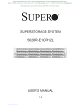
The SuperStorageSystem 6027R-E1R12T is built around the X9DRH-7TF, a dual
processor serverboard based on the Intel C602 chipset and designed to provide
maximum performance. Below are the main features of the X9DRH-7TF. (See Figure
1-1 for a block diagram of the chipset).
Processors
The X9DRH-7TF supports single or dual Intel® E5-2600 Series (Socket R) pro-
cessors in LGA 2011 sockets up to 130 watts. Please refer to our web site for a
complete listing of supported processors (www.supermicro.com).
Memory
The X9DRH-7TF has sixteen DIMM slots that can support up to 512 GB of ECC
registered/unbuffered DDR3-1600/1066/800 memory. Please refer to Chapter 5 for
details on installing memory.
SAS
An LSI 2208 hardware RAID controller provides support for eight SAS 2.0 ports,
which are RAID 0, 1, 5, 6, 10, 50 and 60 capable.
SATA
A SATA controller is integrated into the C602 chipset to provide a 6+4 port SATA
subsystem, which is RAID 0, 1, 10 and 5 capable. Two ports support SATA 3.0 (I-
SATA0/1) and 6+2 support SATA 2.0 (I-SATA2-5).
PCI Expansion Slots
The X9DRH-7TF has six PCI-E 3.0 x8 (in x16 slots), two PCI-E 3.0 x8 and one
PCI-E 3.0 x16 slots. Note that the PCI slots are controlled by the CPU so some
slots may not be available when two CPUs are not installed on the board at the
same time. See the serverboard layout in Chapter 5 for details.
I/O Ports
The color-coded I/O ports include one COM port, a VGA (monitor) port, four USB,
two Ethernet LAN ports (10 Gb ports on the 6027R-E1R12T and 1 Gb ports on the
6027R-E1R12T) and a dedicated IPMI LAN port.

1-3
Chapter 1: Introduction
Graphics Controller
The X9DRH-7TF features an integrated Matrox G200eW video controller. The
G200eW is a 2D/3D/video accelerator chip with a 128-bit core.
1-3 Server Chassis Features
The SC826BE16-R920LPB is an ATX form factor chassis designed to be used in a
2U rackmount confi guration. The following is a general outline of the main features
of the SC826BE16-R920LPB server chassis.
System Power
The SC826BE16-R920LPB features a redundant 920W power supply composed of
two separate power modules. This power redundancy feature allows you to replace
a failed power supply module without shutting down the system.
Hard Drive Subsystem
The SC826BE16-R920LPB chassis was designed to support twelve hot-swap
SATA or SAS hard drives.
Front Control Panel
The control panel on the SC826BE16-R920LPB provides you with system monitor-
ing and control. LEDs indicate system power, HDD activity, network activity, system
information and power supply failure. A main power button and a system reset but-
ton are also included. In addition, two USB ports have been incorporated into the
control panel to provide front side USB access.
Cooling System
The SC826BE16-R920LPB chassis has an innovative cooling design that includes
three 8-cm hot-plug system cooling fans located in the middle section of the chas-
sis. An air shroud channels the airfl ow from the system fans to effi ciently cool the
processor area of the system. The power supply module also includes a cooling fan.

1-4
SuperStorageSystem 6027R-E1R12T User's Manual
Figure 1-1. Chipset Block Diagram
Note: This is a general block diagram. Please see Chapter 5 for details.
KB
MS
#G-1
#G-2
PORTs#4~7
PORTs#0~3
800/1066/1333/1600
DDRIII
P0
#F-2
#F-1
#E-2
#E-1
DDRIII
#B-2
#B-1
#A-2
#A-1
QPI
8G
LANE6
PCI-E X8
USB 2.0
E5-2600
PCH
C602
SSB
PCI-E X8 G3
DMI2
PCI
LANE1/2/3/4
SPI
SIO
W83527
DMI2
USB
I-SATA 0/1
2 Rear
4 Front
1 Type-A
BMC
WPCM450
PCI-E X8
PCI-E X8 G3
PCI
#C-1
#C-2
PCI-E X8 G3
SAS2
8 SNB CORE
DDR-III
E5-2600
8 SNB CORE
DDR-III
QPI
8G
4GB/s
SAS
SAS
P1
P1
P0
SLOT 3
SLOT 1
SLOT 2
SLOT 5
SLOT 6
SLOT 7
SLOT 4
PCI-E X8
PCI-E X8
PCI-E X8 G3
PCI-E X8 G3
PCI-E X8 G3
DMI2#2A #1 #2A #2B #3#1 #3A #3C #2C DMI2
SAS2208
I350/X540
LAN
VGA
PCI-E X8
COM1
External
COM2
Internal
Optional
PCI-E X16
PCI-E X8
PCI-E X8
PCI-E X8 G3
PCI-E X16 G3
SCU0
SATA
#0~#3
#0~#1
#0~#6
800/1066/1333/1600
(CPU1)
(CPU2)
#D1
#D-2
#H-2
#H-1
SATA3.0
3.0 Gb/S
Group2: SATA2.0
from SCU
S-SATA0~3
SATA2.0
Group3:
SATA2.0
3.0 Gb/S
SATA2.0
I-SATA 2~5
Group1:
SATA 3.0
6.0 Gb/S
#2~#5

1-5
Chapter 1: Introduction
1-4 Contacting Supermicro
Headquarters
Address: Super Micro Computer, Inc.
980 Rock Ave.
San Jose, CA 95131 U.S.A.
Tel: +1 (408) 503-8000
Fax: +1 (408) 503-8008
Email: [email protected] (General Information)
[email protected] (Technical Support)
Web Site:
www.supermicro.com
Europe
Address: Super Micro Computer B.V.
Het Sterrenbeeld 28, 5215 ML
's-Hertogenbosch, The Netherlands
Tel: +31 (0) 73-6400390
Fax: +31 (0) 73-6416525
Email: [email protected] (General Information)
[email protected] (Technical Support)
[email protected] (Customer Support)
Asia-Pacifi c
Address: Super Micro Computer, Inc.
4F, No. 232-1, Liancheng Rd
Chung-Ho Dist., New Taipei City 235
Taiwan
Tel: +886-(2) 8226-3990
Fax: +886-(2) 8226-3991
Web Site:
www.supermicro.com.tw
Technical Support:
Email: [email protected]
Tel: +886-(2)-8226-3990

1-6
SuperStorageSystem 6027R-E1R12T User's Manual
Notes

2-1
Chapter 2: Server Installation
Chapter 2
Server Installation
2-1 Overview
This chapter provides a quick setup checklist to get your chassis up and running.
Following these steps in the order given should enable you to have the system
operational within a minimum amount of time.
2-2 Unpacking the System
You should inspect the box the chassis was shipped in and note if it was damaged
in any way. If the chassis itself shows damage you should fi le a damage claim with
the carrier who delivered it.
Decide on a suitable location for the rack unit that will hold your chassis. It should
be situated in a clean, dust-free area that is well ventilated. Avoid areas where
heat, electrical noise and electromagnetic fi elds are generated. You will also need
it placed near a grounded power outlet. Be sure to read the Rack and Server Pre-
cautions in the next section.
2-3 Preparing for Setup
The box your chassis was shipped in should include two sets of rail assemblies,
two rail mounting brackets and the mounting screws you will need to install the
system into the rack. Please read this section in its entirety before you begin the
installation procedure outlined in the sections that follow.
Choosing a Setup Location
• Leave enough clearance in front of the rack to enable you to open the front
door completely (~25 inches).
• Leave approximately 30 inches of clearance in the back of the rack to allow for
suffi cient airfl ow and ease in servicing.
• This product is for installation only in a Restricted Access Location (dedicated
equipment rooms, service closets and the like).

SuperStorageSystem 6027R-E1R12T User's Manual
2-2
2-4 Warnings and Precautions
Rack Precautions
• Ensure that the leveling jacks on the bottom of the rack are fully extended to
the fl oor with the full weight of the rack resting on them.
• In single rack installation, stabilizers should be attached to the rack.
• In multiple rack installations, the racks should be coupled together.
• Always make sure the rack is stable before extending a component from the
rack.
• You should extend only one component at a time - extending two or more si-
multaneously may cause the rack to become unstable.
General Server Precautions
• Review the electrical and general safety precautions that came with the com-
ponents you are adding to your chassis.
• Determine the placement of each component in the rack before you install the
rails.
• Install the heaviest server components on the bottom of the rack fi rst, and then
work up.
• Use a regulating uninterruptible power supply (UPS) to protect the server from
power surges, voltage spikes and to keep your system operating in case of a
power failure.
• Allow the hot plug hard drives and power supply modules to cool before touch-
ing them.
• Always keep the rack's front door and all panels and components on the servers
closed when not servicing to maintain proper cooling.

2-3
Chapter 2: Server Installation
Rack Mounting Considerations
Ambient Operating Temperature
If installed in a closed or multi-unit rack assembly, the ambient operating tempera-
ture of the rack environment may be greater than the ambient temperature of the
room. Therefore, consideration should be given to installing the equipment in an
environment compatible with the manufacturer’s maximum rated ambient tempera-
ture (Tmra).
Reduced Airfl ow
Equipment should be mounted into a rack so that the amount of airfl ow required
for safe operation is not compromised.
Mechanical Loading
Equipment should be mounted into a rack so that a hazardous condition does not
arise due to uneven mechanical loading.
Circuit Overloading
Consideration should be given to the connection of the equipment to the power
supply circuitry and the effect that any possible overloading of circuits might have
on overcurrent protection and power supply wiring. Appropriate consideration of
equipment nameplate ratings should be used when addressing this concern.
Reliable Ground
A reliable ground must be maintained at all times. To ensure this, the rack itself
should be grounded. Particular attention should be given to power supply connec-
tions other than the direct connections to the branch circuit (i.e. the use of power
strips, etc.).
Warning! To prevent bodily injury when mounting or servicing this unit in a
rack, you must take special precautions to ensure that the system remains
stable. The following guidelines are provided to ensure your safety:
• This unit should be mounted at the bottom of the rack if it is the only unit in
the rack.
• When mounting this unit in a partially fi lled rack, load the rack from the bottom
to the top with the heaviest component at the bottom of the rack.
• If the rack is provided with stabilizing devices, install the stabilizers before
mounting or servicing the unit in the rack.

SuperStorageSystem 6027R-E1R12T User's Manual
2-4
2-5 Rack Mounting Instructions
This section provides information on installing the SC826 chassis into a rack unit
with the rails provided. There are a variety of rack units on the market, which may
mean the assembly procedure will differ slightly. You should also refer to the instal-
lation instructions that came with the rack unit you are using.
NOTE: This rail will fi t a rack between 26" and 33.5" deep.
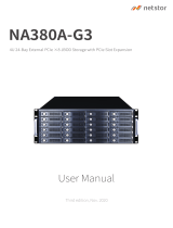
Identifying the Sections of the Rack Rails
The chassis package includes two rack rail assemblies in the rack mounting kit.
Each assembly consists of two sections: an inner fi xed chassis rail that secures
directly to the server chassis and an outer fi xed rack rail that secures directly to
the rack itself.
Figure 2-1. Identifying the Sections of the Rack Rails
Inner Rails
(Inner Rail is preinstalled
to the chassis)
Inner Rail Extensions
Locking Tabs
Both chassis rails have a locking tab. The tabs lock the server into place when
installed and pushed fully into the rack. These tabs also lock the server in place
when fully extended from the rack. This prevents the server from coming completely
out of the rack when it is pulled out for servicing.
Rail Locking Tabs
/