Page is loading ...

SUPER
SUPERSERVER
2028UT-BC1NRT
2028UT-BTNRT
®
USER’S MANUAL
Revision 1.0

ii
The information in this User’s Manual has been carefully reviewed and is believed to be accurate.
The vendor assumes no responsibility for any inaccuracies that may be contained in this document,
makes no commitment to update or to keep current the information in this manual, or to notify any
person or organization of the updates. Please Note: For the most up-to-date version of this
manual, please see our web site at www.supermicro.com.
Super Micro Computer, Inc. ("Supermicro") reserves the right to make changes to the product
described in this manual at any time and without notice. This product, including software and
documentation, is the property of Supermicro and/or its licensors, and is supplied only under a
license. Any use or reproduction of this product is not allowed, except as expressly permitted by
the terms of said license.
IN NO EVENT WILL SUPERMICRO BE LIABLE FOR DIRECT, INDIRECT, SPECIAL, INCIDENTAL,
SPECULATIVE OR CONSEQUENTIAL DAMAGES ARISING FROM THE USE OR INABILITY TO
USE THIS PRODUCT OR DOCUMENTATION, EVEN IF ADVISED OF THE POSSIBILITY OF
SUCH DAMAGES. IN PARTICULAR, SUPERMICRO SHALL NOT HAVE LIABILITY FOR ANY
HARDWARE, SOFTWARE, OR DATA STORED OR USED WITH THE PRODUCT, INCLUDING THE
COSTS OF REPAIRING, REPLACING, INTEGRATING, INSTALLING OR RECOVERING SUCH
HARDWARE, SOFTWARE, OR DATA.
Any disputes arising between manufacturer and customer shall be governed by the laws of Santa
Clara County in the State of California, USA. The State of California, County of Santa Clara shall
be the exclusive venue for the resolution of any such disputes. Super Micro's total liability for all
claims will not exceed the price paid for the hardware product.
FCC Statement: This equipment has been tested and found to comply with the limits for a Class
A digital device pursuant to Part 15 of the FCC Rules. These limits are designed to provide
reasonable protection against harmful interference when the equipment is operated in a commercial
environment. This equipment generates, uses, and can radiate radio frequency energy and, if not
installed and used in accordance with the manufacturer’s instruction manual, may cause harmful
interference with radio communications. Operation of this equipment in a residential area is likely
to cause harmful interference, in which case you will be required to correct the interference at your
own expense.
California Best Management Practices Regulations for Perchlorate Materials: This Perchlorate
warning applies only to products containing CR (Manganese Dioxide) Lithium coin cells. “Perchlorate
Material-special handling may apply. See www.dtsc.ca.gov/hazardouswaste/perchlorate”
WARNING: Handling of lead solder materials used in this
product may expose you to lead, a chemical known to
the State of California to cause birth defects and other
reproductive harm.
Manual Revision 1.0
Release Date: November 4, 2014
Unless you request and receive written permission from Super Micro Computer, Inc., you may not
copy any part of this document.
Information in this document is subject to change without notice. Other products and companies
referred to herein are trademarks or registered trademarks of their respective companies or mark
holders.
Copyright © 2014 by Super Micro Computer, Inc.
All rights reserved.
Printed in the United States of America

Preface
iii
Preface
About This Manual
This manual is written for professional system integrators and PC technicians. It
provides information for the installation and maintenance which should be performed
by experienced technicians only.
Notes
For your system to work properly, please follow the links below to download all
necessary drivers/utilities and the user’s manual for your server.
•Supermicro product manuals: http://www.supermicro.com/support/manuals/
•Product drivers and utilities: ftp://ftp.supermicro.com
•Product safety info: http://super-dev/about/policies/safety_information.cfm
If you have any questions, please contact our support team at:
This manual may be periodically updated without notice. Please check the
Supermicro Web site for possible updates to the manual revision level.
Warnings
Special attention should be given to the following symbols used in this manual.
Warning! Indicates high voltage may be encountered when performing
a procedure.
Warning! Indicates important information given to prevent equipment/
property damage or personal injury.

SUPERSERVER 2028UT-BTNRT/BC1NRT User's Manual
iv
Contents
Chapter 1 Introduction
1-1 Overview ......................................................................................................... 1-1
1-2 Serverboard Features .................................................................................... 1-2
Processors ...................................................................................................... 1-2
Memory ........................................................................................................... 1-2
Serial ATA ....................................................................................................... 1-2
Expansion Slots .............................................................................................. 1-2
Input/Output Ports ........................................................................................... 1-2
IPMI ................................................................................................................. 1-3
1-3 Server Chassis Features ................................................................................ 1-3
System Power ................................................................................................. 1-3
Drive Bays ....................................................................................................... 1-3
Front Control Panel ......................................................................................... 1-3
Cooling System ............................................................................................... 1-3
1-4 Contacting Supermicro .................................................................................... 1-5
Chapter 2 Server Installation
2-1 Overview ......................................................................................................... 2-1
2-2 Preparing for Setup ......................................................................................... 2-1
Choosing a Setup Location ............................................................................. 2-1
Rack Precautions ............................................................................................ 2-2
Server Precautions .......................................................................................... 2-2
Rack Mounting Considerations ....................................................................... 2-2
Ambient Operating Temperature ................................................................ 2-2
Airow ......................................................................................................... 2-3
Mechanical Loading ................................................................................... 2-3
Circuit Overloading ..................................................................................... 2-3
Reliable Ground ......................................................................................... 2-3
2-3 Installing the System into a Rack .................................................................. 2-4
Identifying the Sections of the Rack Rails ...................................................... 2-4
Releasing the Inner Rail ................................................................................. 2-5
Installing the Inner Rails on the Chassis ........................................................ 2-6
Installing the Outer Rails onto the Rack ......................................................... 2-7
Sliding the Chassis onto the Rack Rails ......................................................... 2-8
Chapter 3 System Interface
3-1 Overview ......................................................................................................... 3-1
3-2 Control Panel Buttons ..................................................................................... 3-2

Preface
v
3-3 Control Panel LEDs ........................................................................................ 3-2
Overheating ..................................................................................................... 3-3
Overheat Temperature Setting ................................................................... 3-3
Responses .................................................................................................. 3-3
3-4 Drive Carrier LEDs .......................................................................................... 3-3
3-5 Power Supply LEDs ........................................................................................ 3-4
Chapter 4 Standardized Warning Statements for AC Systems
About Standardized Warning Statements ....................................................... 4-1
Warning Denition ........................................................................................... 4-1
Installation Instructions .................................................................................... 4-4
Circuit Breaker ................................................................................................ 4-5
Power Disconnection Warning ........................................................................ 4-6
Equipment Installation ..................................................................................... 4-8
Restricted Area ................................................................................................ 4-9
Battery Handling ............................................................................................ 4-10
Redundant Power Supplies .......................................................................... 4-12
Backplane Voltage ........................................................................................ 4-13
Comply with Local and National Electrical Codes ........................................ 4-14
Product Disposal ........................................................................................... 4-15
Hot Swap Fan Warning ................................................................................. 4-16
Power Cable and AC Adapter ...................................................................... 4-18
Chapter 5 Advanced Serverboard Setup
5-1 Handling the Serverboard ............................................................................... 5-1
Precautions ..................................................................................................... 5-1
Unpacking ....................................................................................................... 5-1
5-2 Installing the Processor and Heatsink ............................................................ 5-2
Installing an LGA 2011 Processor ................................................................... 5-2
Installing a CPU Heatsink ............................................................................... 5-5
Removing the Heatsink .................................................................................. 5-5
5-3 Connecting Cables .......................................................................................... 5-6
Connecting Data Cables ................................................................................. 5-6
Connecting Power Cables .............................................................................. 5-6
5-4 I/O Ports .......................................................................................................... 5-7
5-5 Installing Memory ............................................................................................ 5-8
Memory Support .............................................................................................. 5-9
Processor & Memory Module Population Conguration ............................ 5-9
Fully-Populated Conguration .................................................................... 5-9
Half-Populated Conguration ..................................................................... 5-9

SUPERSERVER 2028UT-BTNRT/BC1NRT User's Manual
vi
RDIMM/LRDIMM DDR3 ECC in Performance Mode (2:1) ..................... 5-10
RDIMM/LRDIMM DDR3 ECC in Lockstep Mode (1:1) ........................... 5-10
5-6 Serverboard Details .......................................................................................5-11
Quick Reference ........................................................................................... 5-12
5-7 Connector Denitions .................................................................................... 5-14
5-8 Jumper Settings ............................................................................................ 5-16
5-9 Onboard Indicators ........................................................................................ 5-19
5-10 SATA Ports .................................................................................................... 5-20
5-11 Installing Software ......................................................................................... 5-21
SuperDoctor
®
5 ............................................................................................. 5-22
5-12 Onboard Battery ............................................................................................ 5-24
Chapter 6 Advanced Chassis Setup
6-1 Removing the Power ....................................................................................... 6-1
6-2 Chassis Cover ................................................................................................. 6-2
6-3 Installing Drives ............................................................................................... 6-3
6-4 Expansion Card Setup ................................................................................... 6-6
6-5 System Cooling ............................................................................................... 6-7
System Fan Failure ......................................................................................... 6-7
Air Shroud ....................................................................................................... 6-9
6-6 Power Supply ................................................................................................ 6-10
Chapter 7 BIOS
7-1 Introduction ...................................................................................................... 7-1
Starting BIOS Setup Utility .............................................................................. 7-1
How To Change the Conguration Data ......................................................... 7-2
Starting the Setup Utility ................................................................................. 7-2
7-2 Main Setup ...................................................................................................... 7-2
7-3 Advanced Setup Congurations...................................................................... 7-4
7-4 Event Logs .................................................................................................... 7-46
7-5 IPMI ...............................................................................................................7-48
7-6 Security ......................................................................................................... 7-50
7-7 Boot ............................................................................................................... 7-51
7-8 Save & Exit ................................................................................................... 7-53
Appendix A BIOS POST Error Codes .................................................... A-1
Appendix B System Specications ........................................................ B-1

Chapter 1
Introduction
1-1 Overview
This chapter provides a brief outline of the functions and features of the
2028UT-BTNRT/BC1NRT. The server is two independent computing nodes, each
based on the X10DBT-T serverboard, all in the SC227HD-R1K28 chassis. The
2028UT-BC1NRT model includes the LSI SAS3108 12Gb/s SAS RAID-on-Chip.
In addition to the serverboards and chassis, several important parts that are included
with the system are listed below.
•Backplanes:
•Supports sixteen 2.5" SAS/SATA drives and four PCIe SSD drive (BPN-
SAS3-227HD-N2)
•Two PBF Right 1U adapter cards for EX DP 2U, 8x PCIe gen3 lanes (BPN-
ADP-8PCIE3-1UBR)
•For 2028UT-BC1NRT only, two EX DP 2U, SAS 3108 daughter cards (BPN-
ADP-8S3108-1UBL)
•For 2028UT-BTNRT only, two PBF Left 1U adapter cards for EX DP 2U, 8x
SATA3 ports (BPN-ADP-8SATA3-1UBL)
•Riser card (RSC-R1UW-2E16)
•Air shroud (MCP-310-22701)
•Heat sink (SNK-P0057PS)
•One rail set (MCP-290-00053, MCP-290-00060)
Note: For your system to work properly, please follow the links below to download
all necessary drivers/utilities and the user’s manual for your server.
•Product manuals: http://www.supermicro.com/support/manuals/
•Product drivers and utilities: ftp://ftp.supermicro.com
•Product safety information:
http://super-dev/about/policies/safety_information.cfm
For support, email [email protected].
Chapter 1: Introduction
1-1

1-2
SUPERSERVER 2028UT-BTNRT/BC1NRT User's Manual
1-2 Serverboard Features
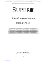
At the heart of each node is the X10DBT-T, a dual processor serverboard based
on the Intel C602 chipset. Below are the main features of the serverboard. See
Figure 1-1 for a block diagram.
Processors
The serverboard supports two Intel Xeon E7-8800 v2/E7-4800 v2/E7-2800 v2
processors in LGA 2011 sockets (Socket R1). Please refer to the serverboard
description pages on our web site for a complete listing of supported processors
(www.supermicro.com).
Memory
The serverboard has 32 DIMM slots that can support up to 1TB registered
(RDIMM) or up to 2TB of load reduced (LRDIMM) memory. Memory Type is
1600/1333/1066/800MHz ECC DDR3 SDRAM 72-bit, 240-pin gold-plated DIMMs
Modules of the same size and speed are recommended. See Chapter 5 for details.
Serial ATA
The serverboard supports eight SATA ports, that is two SATA3 and six SATA2. These
allow RAID 0, 1, 5, 10. The SATA drives are hot-swappable. Additional SATA ports
are available with a PCIe expansion card.
Expansion Slots
Each node has:
•Two PCI Express x16 slots for full height, half length expansion cards
•One PCIe x8 microLP card
•Two solid-state drive (SSD) slots for non-volatile memory express (NVMe) drives
with Windows 8 support
Input/Output Ports
The rear I/O ports for each node include two 10Gbase-T Ethernet LAN ports, two
USB 2.0 ports, one dedicated IPMI LAN port, a VGA (monitor) port, one serial
COM port.

1-3
Chapter 1: Introduction
IPMI
IPMI (Intelligent Platform Management Interface) is a hardware-level interface
specication that provides remote access, monitoring and administration for
Supermicro server platforms. IPMI allows server administrators to view a server’s
hardware status remotely, receive an alarm automatically if a failure occurs, and
power cycle a system that is non-responsive.
1-3 Server Chassis Features
Some features of the SC227HD-R1K28 chassis are listed below.
System Power
The system features two high-efciency, hot-plug, 80 Plus Platinum level, digital
1280W redundant power supplies. One power module may be removed without
shutting down the system. See Chapter 6 for details.
Drive Bays
The chassis includes twenty 2.5" drive bays and four dummy bays to allow for
cooling. Each node can control eight hot-swappable SATA or SAS drives and two
NVMe (Non Volatile Memory Express) drives. .
Front Control Panel
Two control panels provide on the front of the chassis a system monitoring and
control interface for each computing node. LEDs indicate network activity, system
overheat, UID and power supply failure. A main power button and a UID button
are also included.
Cooling System
The chassis has an innovative cooling design that includes four 4-cm PWM (Pulse
Width Modulated) fans and an air shroud to focus airow where it is needed. The
power supply module also includes a cooling fan. All fans operate continuously.
The CPU and chassis fan speeds are controlled by IPMI Thermal Management. A
thermal control sensor monitors the CPU temperature in real time and controls fan.
The chassis thermal circuitry monitors the overall system temperature and alerts
when the chassis temperature is too high.

1-4
SUPERSERVER 2028UT-BTNRT/BC1NRT User's Manual
1
D
C
B
P0
P0
P1
P1
PCI-E x8 GEN3
CPU1
CPU2
PE0 PE1 DMI
DDR3 DIMM
PCI-32bit
164E/164H
SPI FLASH
A
LPC
DDR3 DIMM
#2
PCIe Gen3 x8 (0-7)
PCIe Gen3 x8 (8-15)
SXB1
PCIe Gen3 x16
SXB4
TPM Header
USB
LAN
I350 /
X540
2 ports
RJ45 RJ45
UM56
PCIe Gen3 x16
DMI Gen2 x4
PROCESSOR
PROCESSOR
QPI
U1
U3
U3G1
UMB1
PCIe Gen3 x16
SXB2
SSB
QPI
DMI
VGA BMC
VGA CONN
AST2400
DDR2
PHY1
LAN
RTL8211E
SPI
B
C
D
Left Socket
Right Socket
#1
PCIe Gen3 x16
MicroLP
PCIe Gen3 x8 (0-7)
PCIe Gen3 x8 (8-15)
PCI-E x16 Gen 3
DDR3 DIMM
DDR3 DIMM
#2
#1
DDR3 DIMM
DDR3 DIMM
DDR3 DIMM
#2
#1
DDR3 DIMM
#2
B
A
#1
DDR3 DIMM
DDR3 DIMM
DDR3 DIMM
#2
#1
DDR3 DIMM
#2
DDR3 DIMM
DDR3 DIMM
DDR3 DIMM
#2
#1
DDR3 DIMM
#2
A
B
#1
C
D
#1
PCI-E x16 Gen 3
DDR3 DIMM
#1
DDR3 DIMM
#2
DDR3 DIMM
#1
DDR3 DIMM
#2
DDR3 DIMM
#1
DDR3 DIMM
#2
DDR3 DIMM
#1
DDR3 DIMM
#2
DDR3 DIMM
#1
DDR3 DIMM
#2
DDR3 DIMM
#1
DDR3 DIMM
#2
P1M1CD
DDR3 DIMM
#1
DDR3 DIMM
#2
DDR3 DIMM
#1
DDR3 DIMM
#2
Combine with SATA/SAS interface
PCI-E x8 GEN3
PCI-E x8 GEN3
3/1.5 Gb/s
6 Gb/s for Port 0,1
3/1.5 Gb/s
SATA2 #4 DOM
SATA2 #5 DOM
SATA3 #0
SATA3 #1
SATA2 #3
SATA2 #0
SATA2 #1
SATA2 #3
SATA2 #2
SATA2 #2
USB 2.0
REAR
MicroLP
0,1
4,5
USB Type-A
D
C
A
B
D
C
SMI2
CH1
COM1
CONN
COM1
SXB3
2
NVMe8
SXBP
SCU
SATA
BIOS 16MB
CH0
SMI2
CH3
SMI2
CH2
SMI2
CH3
SMI2
CH2
SMI2
CH0
SMI2
CH1
SMI2
C102
P1M1AB
P2M2CD
P2M2AB
PE1
PE0
DMI
P1M2AB
P1M2CD
P2M1AB
P2M1CD
Intel
C102
Intel
C102
Intel
C102
Intel
C102
Intel
C102
Intel
C102
Intel
C102
Intel
Figure 1-1. General System Block Diagram

1-5
Chapter 1: Introduction
1-4 Contacting Supermicro
Headquarters
Address: Super Micro Computer, Inc.
980 Rock Ave.
San Jose, CA 95131 U.S.A.
Tel: +1 (408) 503-8000
Fax: +1 (408) 503-8008
Email: [email protected] (General Information)
[email protected] (Technical Support)
Web Site: www.supermicro.com
Europe
Address: Super Micro Computer B.V.
Het Sterrenbeeld 28, 5215 ML
's-Hertogenbosch, The Netherlands
Tel: +31 (0) 73-6400390
Fax: +31 (0) 73-6416525
Email: [email protected] (General Information)
[email protected] (Technical Support)
[email protected] (Customer Support)
Web Site: www.supermicro.nl
Asia-Pacic
Address: Super Micro Computer, Inc.
3F, No. 150, Jian 1st Rd.
Zhonghe Dist., New Taipei City 235
Taiwan (R.O.C)
Tel: +886-(2) 8226-3990
Fax: +886-(2) 8226-3992
Email: [email protected]
Web Site: www.supermicro.com.tw

1-6
SUPERSERVER 2028UT-BTNRT/BC1NRT User's Manual
Notes

Chapter 2: Server Installation
2-1
Chapter 2
Server Installation
2-1 Overview
This chapter provides advice and instructions for mounting your system in a server
rack If your system is not already fully integrated with a serverboard, processors,
system memory etc., refer to Chapter 4 for details on installing those specic
components.
Caution: Electrostatic Discharge (ESD) can damage electronic components. To
prevent such damage to your serverboard, it is important that you handle it very
carefully. See Chapter 5 for a list of measures to protect your equipment from ESD.
2-2 Preparing for Setup
The box in which the system was shipped should include the rackmount hardware
needed to install it into the rack. Please read this section in its entirety before you
begin the installation.
Choosing a Setup Location
•Leave enough clearance in front of the rack so that you can open the front
door completely (~25 inches) and approximately 30 inches of clearance in the
back of the rack to allow sufcient space for airow and access when servicing.
•This product should be installed only in a Restricted Access Location (dedicated
equipment rooms, service closets, etc.).
•This product is not suitable for use with visual display workplace devices
acccording to §2 of the the German Ordinance for Work with Visual Display Units.

2-2
SUPERSERVER 2028UT-BTNRT/BC1NRT Manual
Rack Precautions
•Ensure that the leveling jacks on the bottom of the rack are extended to the
oor so that the full weight of the rack rests on them.
•In single rack installations, stabilizers should be attached to the rack. In multiple
rack installations, the racks should be coupled together.
•Always make sure the rack is stable before extending a server or other com-
ponent from the rack.
•You should extend only one server or component at a time - extending two or
more simultaneously may cause the rack to become unstable.
Server Precautions
•Review the electrical and general safety precautions in Chapter 3.
•Determine the placement of each component in the rack before you install the
rails.
•Install the heaviest server components at the bottom of the rack rst and then
work your way up.
•Use a regulating uninterruptible power supply (UPS) to protect the server from
power surges and voltage spikes and to keep your system operating in case
of a power failure.
•Allow any drives and power supply modules to cool before touching them.
•When not servicing, always keep the front door of the rack and all covers/panels
on the servers closed to maintain proper cooling.
Rack Mounting Considerations
Ambient Operating Temperature
If installed in a closed or multi-unit rack assembly, the ambient operating
temperature of the rack environment may be greater than the room's ambient
temperature. Therefore, consideration should be given to installing the equipment
in an environment compatible with the manufacturer’s maximum rated ambient
temperature (Tmra).

Chapter 2: Server Installation
2-3
Airow
Equipment should be mounted into a rack so that the amount of airow required
for safe operation is not compromised.
Mechanical Loading
Equipment should be mounted into a rack so that a hazardous condition does not
arise due to uneven mechanical loading.
Circuit Overloading
Consideration should be given to the connection of the equipment to the power
supply circuitry and the effect that any possible overloading of circuits might have
on overcurrent protection and power supply wiring. Appropriate consideration of
equipment nameplate ratings should be used when addressing this concern.
Reliable Ground
A reliable ground must be maintained at all times. To ensure this, the rack
itself should be grounded. Particular attention should be given to power supply
connections other than the direct connections to the branch circuit (i.e. the use of
power strips, etc.).
To prevent bodily injury when mounting or servicing this unit in a rack, you
must take special precautions to ensure that the system remains stable.
The following guidelines are provided to ensure your safety:
•This unit should be mounted at the bottom of the rack if it is the only unit in
the rack.
•When mounting this unit in a partially lled rack, load the rack from the bottom
to the top with the heaviest component at the bottom of the rack.
•If the rack is provided with stabilizing devices, install the stabilizers before
mounting or servicing the unit in the rack.
•Slide rail mounted equipment is not to be used as a shelf or a work space.

2-4
SUPERSERVER 2028UT-BTNRT/BC1NRT Manual
2-3 Installing the System into a Rack
This section provides information on installing the chassis into a rack unit with the
rails provided. There are a variety of rack units on the market, which may mean
that the assembly procedure will differ slightly from the instructions provided. You
should also refer to the installation instructions that came with the rack unit you are
using. Note: This rail will t a rack between 26.5" and 36.4" deep.
Identifying the Sections of the Rack Rails
The chassis package includes two rail assemblies. Each assembly consists of three
sections: An inner rail that secures directly to the chassis, an outer rail that secures
to the rack, and a middle rail which extends from the outer rail. These assemblies
are specically designed for the left and right side of the chassis.
Figure 3-1. Identifying the Outer Rail, Middle Rail and Inner Rail
(Left Rail Assembly Shown)
Inner Rail
Rail Assembly
(Shown with Rails
Retracted)
This Side Faces
Outward
Locking Tab
Middle Rail
Outer Rail

Chapter 2: Server Installation
2-5
Figure 3-2. Extending and Releasing the Inner Rail
Releasing the Inner Rail
Each inner rail has a locking latch. This latch prevents the server from coming
completely out of the rack when when the chassis is pulled out for servicing.
To mount the rail onto the chassis, rst release the inner rail from the outer rails.
Releasing Inner Rail from the Outer Rails
1. Pull the inner rail out of the outer rail until it is fully extended as illustrated
below.
2. Press the locking tab down to release the inner rail.
3. Pull the inner rail all the way out.
4. Repeat for the other outer rail.
1
1
1
2
1
3

2-6
SUPERSERVER 2028UT-BTNRT/BC1NRT Manual
1
3
1
4
1
4
1
2
Inner Rails
Figure 3-3. Installing the Inner Rails
Installing the Inner Rails on the Chassis
Installing the Inner Rails
1. Identify the left and right inner rails. They are labeled.
2. Place the inner rail rmly against the side of the chassis, aligning the hooks
on the side of the chassis with the holes in the inner rail.
3. Slide the inner rail forward toward the front of the chassis until the quick
release bracket snaps into place, securing the rail to the chassis.
4. Optionally, you can further secure the inner rail to the chassis with a screw.
5. Repeat for the other inner rail.
Figure 3-4. Inner Rails Installed on the Chassis

Chapter 2: Server Installation
2-7
Figure 3-5. Extending and Mounting the Outer Rails
1
1
1
2
1
3
1
4
21D01
L-min=676.00(26.61")(outer rail)
Installing the Outer Rails onto the Rack
Installing the Outer Rails
1. Press upward on the locking tab at the rear end of the middle rail.
2. Push the middle rail back into the outer rail.
3. Hang the hooks on the front of the outer rail onto the square holes on the
front of the rack. If desired, use screws to secure the outer rails to the rack.
4. Pull out the rear of the outer rail, adjusting the length until it just ts within the
posts of the rack.
5. Hang the hooks of the rear section of the outer rail onto the square holes on
the rear of the rack. Take care that the proper holes are used so the rails are
level. If desired, use screws to secure the rear of the outer rail to the rear of
the rack.
6. Repeat for the other outer rail.
Stability hazard. The rack stabilizing mechanism must be in place, or the rack
must be bolted to the oor before you slide the unit out for servicing. Failure to
stabilize the rack can cause the rack to tip over.
Do not use a two post "telco" type rack.

2-8
SUPERSERVER 2028UT-BTNRT/BC1NRT Manual
Figure 3-6. Installing into a Rack
Ball-Bearing
Shuttle
Sliding the Chassis onto the Rack Rails
Warning: Mounting the system into the rack requires at least two people to
support the chassis during installation. Please follow safety recommendations
printed on the rails.
Installing the Chassis into a Rack
1. Extend the outer rails as illustrated above.
2. Align the inner rails of the chassis with the outer rails on the rack.
3. Slide the inner rails into the outer rails, keeping the pressure even on both
sides. When the chassis has been pushed completely into the rack, it should
click into the locked position.
4. Optional screws may be used to hold the front of the chassis to the rack.
Note: The gure above is for illustrative purposes only. Always install servers to
the bottom of the rack rst.
Caution: Do not pick up the server with the front handles. They are designed
to pull the system from a rack only.
/