Page is loading ...

S
UPERMICR
R
ContaCt InformatIon
• www.supermicro.com(Email:[email protected])
• Manuals:http://www.supermicro.com/support/manuals
• Drivers&Utilities:ftp://ftp.supermicro.com
• Safety:http://www.supermicro.com/about/policies/safety_information.cfm
PaCkage Contents
(Appliestoindividual-packonly)
C7X99-OCE / C7X99-OCE-F
QuICk referenCe guIde rev. 1.0b
• One(1)SupermicroMotherboard
• Six(6)SATACables(singlepacked/boxedonly)
• Two(2)SATACables(bulkpackedonly)
MNL-1646-QRG Rev. 1.0b
© 2014 Supermicro Computer Inc. All rights reserved. Reproduction of this document whether in part or in whole is strictly prohibited without Supermicro's written
consent. All Trademarks are property of their respective entities. All information provided is deemed accurate at the time of printing; however, it is not guaranteed.
MNL-1646-QRG
• One(1)I/OShield
• One(1)QuickReferenceGuide
• One(1)DriverCD(C7X99-OCEsinglepacked/boxedonly)
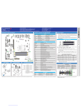
A. PS/2 Keyboard/Mouse Port H. Gb LAN Port 2 L. Center/LFE Out
B. USB 3.0 Port 14 I. USB 3.0 Port 12 M. Surround Out
C. USB 3.0 Port 15 J. USB 3.0 Port 13 N. S/PDIF Out
D. VGA Port* K. Clear CMOS O. Line In
E. Gb LAN Port 1 (shared IPMI*) P. Line Out
F. USB 3.0 Port 10 Q. Mic In
G. USB 3.0 Port 11
MAC CODE
IPMI CODE
BAR CODE
C7X99-OCE-F
REV:1.00
DESIGNED IN USA
SW_BIOSRC
S4
S7
S10
S5
S6
S9
OC_FRONT_PANEL
S8
S11
CLR_CMOS_SW
JUSB30_I2
JAUDIO1
LED4
I-SATA0
I-SATA2
I-SATA4s-SATA0
s-SATA2
AUDIO_FP
JIPMB1
JSD1
MH11
MH2
MH9
MH10
JPW2
CA
LEDM1
JBT1
BT1
+
FAN5
FAN4
FAN1
1
FAN2
4
FAN3
JPL2
JPUSB1
J29
J30
JPME2
JPAC1
JPL1
JI2C1
JI2C2
JPB1
JPG1
JWD1
1
JL2
JL1
JD1
1
JF1
2
19
JPI2C1
JSTBY1
JTPM1
SP1
+
Header for 5V STBY power
HD AUDIO
VGA
LAN1
LAN2
USB 16/17(3.0)
USB 12/13(3.0)
USB 10/11(3.0)
USB 14/15(3.0)
CPU SLOT6 PCI-E 3.0 X16
PCH SLOT5 PCI-E 2.0 X1 (IN X4)
CPU SLOT4 PCI-E 3.0 X8 (IN X16)
PCH SLOT3 PCI-E 2.0 X1 (IN X4)
CPU SLOT2 PCI-E 3.0 X8 (IN X16)
CPU SLOT1 PCI-E 3.0 X8 (IN X16)
2-3:DISABLE
1-2:ENABLE
:WATCH DOG
SPEAKER
PWR LED
:TPM/PORT80
CPU
CHASSIS INTRUSION
JI2C2
2-3:DISABLE
1-2:ENABLE
JI2C1
PWR ON OH/FF NIC1NIC2RST X
CMOS CLEAR
1-2:NORMAL
2-3:BIOS RECOVERY
JBR1
PWR LEDHDD LED NMIX
2-3:ME MANUFACTURING MODE
JPME2
1-2:NORMAL
1-2 ENABLE
2-3 DISABLE
1-2 ENABLE
2-3 DISABLE
:PWR I2C
1-2 ENABLE
2-3 DISABLE
2-3 DISABLE
1-2 ENABLE
1-2 ENABLE
2-3 DISABLE
JPAC1
VGA
USB14/15 WAKE UP
1-2 RST
2-3 NMI
:SATA DOM POWER
DIMMD2
DIMMD1
DIMMC2
DIMMC1
DIMMB2
DIMMB1
DIMMA2
DIMMA1
JBR1
JWD1
JPW1
JPUSB1
JPB1
JPG1
C
A
LE2
I-SATA1
I-SATA3
I-SATA5s-SATA1
s-SATA3
The C7X99-OCE(-F) supports up to 64GB of Unbuffered (UDIMM) DDR4 non-
ECC 2133~3000(OC) MHz in 8 memory slots. Populating these DIMM modules
with a pair of memory modules of the same type and same size will result in
interleaved memory, which will improve memory performance.
Note: For memory optimization, use only DIMM modules that have been validated by Supermicro.
For the latest memory updates, please refer to our website at http://www.supermicro.com/
products/motherboard.
Motherboard Layout and Features
Jumpers, Connectors and LED Indicators
Note: Graphics shown in this quick reference guide are for illustration only. Your components may or may not look exactly the same as drawings shown in this guide.
Back Panel I/O Connectors
Memory Support
Note: Refer to Chapter 2 of the User Manual for detailed information on memory support and CPU/
motherboard installation instructions.
Note: Refer to Chapter 2 of the User Manual for detailed information on jumpers, connectors, and LED indicators.
= mounting hole
A
B
C
D
E
F
G
H
I
Note: Up to 64GB of memory are supported. See chapter 2 of the User Manual for
complete memory population information.
CPU
Jumpers
Connectors and Switches
LED Indicators
DIMM Memory Installation
Memory Population Guidelines
When installing memory modules, the DIMM slots should be populated in the follow-
ing order: DIMMA1, DIMMB1, DIMMC1, DIMMD1 then DIMMA2, DIMMB2, DIMMC2,
DIMMD2.
• Always use DDR4 DIMM modules of the same size, type and speed.
Recommended Population (Balanced)
DIMMA1 DIMMB1 DIMMC1 DIMMD1 DIMMA2 DIMMB2 DIMMC2 DIMMD2 Total System
Memory
4GB 4GB 8GB
4GB 4GB 4GB 4GB 16GB
4GB 4GB 4GB 4GB 4GB 4GB 24GB
4GB 4GB 4GB 4GB 4GB 4GB 4GB 4GB 32GB
LGA 2011-3
I/O BACK PANEL
J
K
L
M
N
O
P
Q
HD Audio
Jumper Description Default
JBT1* Clear CMOS (on board) (See Chpt. 2)
JI
2
C1/JI
2
C2 SMB to PCI Slots Off (Disabled)
JPAC1 Audio Enable Pins 1-2 (Enabled)
JPL1/JPL2 LAN1/LAN2 Enable Pins 1-2 (Enabled)
JPME2 Intel Recovery Mode Pins 2-3 (Disabled)
JWD1 Watch Dog Enable Pins 2-3 (NMI)
JBR1 Restores the BIOS rmware from a USB
memory device (SUPER.ROM)
Pins 1-2 (Normal), set switch to pins 2-3
to recover BIOS
JPUSB1 USB Wake Up Enable (USB14/15) Pins 1-2 (Enabled)
JPB1 BMC Enable/Disable (C7X99-OCE-F only) Pins 1-2 (Enabled)
JPG1 Onboard VGA Enable (C7X99-OCE-F only) Pins 1-2 (Enabled)
Connector Description
I/O Back Panel See Back Panel I/O Connectors, below right
Audio FP Front Panel Audio Header
BT1 Onboard Battery
Fan 1,2,3,4,5 System/CPU Fan Headers (Fan1: CPU Fan)
JD1 Speaker/buzzer (Pins 1~4: External Speaker, Pins 3~4: Buzzer)
JF1 Front Panel Control Header
JL1 Chassis Intrusion Header
JPW1 24-pin ATX Main Power Connector (Required)
JPW2 +12V 4-pin CPU power Connector (Required)
JSD1 SATA DOM (Disk On Module) Power Connector
JSTBY1 Standby Power Header
SP1 Internal Speaker/Buzzer
I-SATA0~5 (Intel X99) SATA 3.0 Ports 0~5 (6Gb/sec), Supports RAID 0, 1 ,5 & 10
s-SATA0~3 (Intel X99) SATA 3.0 Ports 0~3 (6Gb/sec), no RAID functions
USB 16/17 Front Panel Accessible USB 3.0 Headers 16/17
OC FRONT PANEL Header for the Over-Clocking Control Panel
S4 Power Button
S11 BIOS Restore
S5, S6, S7 Over-Clocking Buttons OC1(15%), OC2(20-25%), OC3 (User-Dened in BIOS)
S9 Home Button, Default setting (non-OC)
S10 Memory Overclocking Button
S8 Clear CMOS Button (on board)
JPI2C1 Power Supply SMBbus I2C Header.
JTPM1 Trusted Platform Module Header
COM1 Serial Port Header for COM1
JIPMB1 System Management Bus header (for IPMI only)
LED Description Color/State Status
LEDM1 BMC Heartbeat* Green: Blinking BMC Normal
LE2 Power LED Geen: Steady System On/Running
LED4 Status Display (C7X99-OCE only) Digital Readout Download the status codes below**
Note for VGA Cards: For a single VGA card, install the VGA card into the SLOT6 (x16) slot. For CrossFireX™ mode (two VGA
cards linked), install one card each into SLOT6 (x16) and SLOT4 (x16) slots.
DIMMB2
DIMMA2
DIMMA1 (Blue Slot)
DIMMB1 (Blue Slot)
** Download the AMI status codes at http://www.ami.com/support/doc/ami_aptio_4.x_status_codes_pub.pdf
Intel Core i7
DIMMC1 (Blue Slot)
DIMMD1 (Blue Slot)
DIMMD2
DIMMC2
I/O Back Panel
Front Panel Control (JF1)
CPU Installation
OPEN 1st
Screw #2
Screw #3
Screw #4
Align Socket Keys
Power Button
OH/Fan Fail LED
1
NIC1 LED
Reset Button
2
Power Fail LED
HDD LED
Power LED
#3~4
#1~2
Vcc
Vcc
Vcc
Vcc
Ground
Ground
1920
Vcc
X
Ground
NMI
X
Vcc
NIC2 LED
Heatsink Installation
* C7X99-OCE-F only
Note for Intel CPUs: PCIe Slot#1 (x4) and Slot#4 (x16) are disabled when an Intel Core i7-5820K is installed. This is due to
the CPU having a limitation of 28 PCIe lanes, compared to 40 with other CPU models.
* C7X99-OCE-F only
C7X99-OCE-F
Only
* For the C7X99-OCE-F, reboot time may be longer after clearing CMOS. This is due to the additional IPMI functions.
/