READ AND SAVE THESE INSTRUCTIONS
HUMIDI-TECH and
HUMIDI-TECH DI
ELECTRIC STEAM HUMIDIFIERS
Installation, Operation
and
Maintenance Manual
®

2
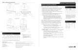
TABLE OF CONTENTS
To the purchaser and installer
Thank you for purchasing our HUMIDI-TECH
®
humidifier. We have designed and built this equipment to give
you complete satisfaction and trouble-free service for many years. Familiarizing yourself with this manual will
help ensure proper operation of the equipment for years to come.
This manual covers the installation and maintenance procedures for both the HUMIDI-TECH and
HUMIDI-TECH DI humidifiers.
DRI-STEEM Humidifier Company
General information
Product overview ................................................................. 3
Dimensions .......................................................................... 4
Electrical specifications, capacities and weights ................. 5
Installation
Locating and mounting the humidifier .................................. 6
Piping ................................................................................... 6
Wiring .................................................................................. 9
Dispersion
Using space distribution units (SDU-E and SDU-I) ..... 11
Using dispersion tubes ................................................ 14
Using a RAPID-SORB
®
dispersion assembly .............. 16
Drip tee installation ...................................................... 17
Interconnecting piping tables ....................................... 18
Operation
Start-up procedures ........................................................... 19
Control ............................................................................... 20
Maintenance
Maintenance procedures ................................................... 21
Troubleshooting guide ....................................................... 24
Replacement parts............................................................. 26
Warranty ........................................................................... 32

3
HUMIDI-TECH
®
HUMIDIFIER OVERVIEW
Deionized water models
(HUMIDI-TECH DI)
The HUMIDI-TECH DI, shown here,
is specifically designed for use with
deionized or reverse osmosis water.
Standard water models
(HUMIDI-TECH)
The standard water HUMIDI-TECH unit
requires water conductivity of at least
100 µS/cm to operate. It will not
operate with water treated
by reverse osmosis or
deionization processes
(see DI water model below).
OM-82-4
Removable
evaporating
chamber
Slide assembly under evaporating chamber
provides easy removal for cleaning
INCOLOY alloy-sheathed
immersion heaters
Keyholes for
wall mounting
Water fill DN10
(3/8") (female)
DN40 or DN50 flexible
vapor hose, pipe or
tubing connects to
dispersion tube(s) or
to an SDU
Condensate
return line
Duct
Electrical area
Electrical conduit
knockouts
DN20 (¾") threaded
skimmer port and
overflow drain
Water fill access hole
Condensate
return line
Electrical area
Removable
evaporating
chamber
INCOLOY alloy-sheathed
immersion heaters
Duct
Electrical conduit knockouts
Slide assembly under
evaporating chamber provides
easy removal for cleaning
Water fill access hole
Keyholes for
wall mounting
Water fill DN10
(3/8") (female)
Float cutoff switch
OM-82-5
Ball valve
DN20 (¾") threaded skimmer
port and overflow drain
DN40 or DN50 flexible vapor
hose, pipe or tubing connects to
dispersion tube(s) or to an SDU

4
HUMIDI-TECH
®
DIMENSIONS
50 mm
409 mm
57 mm
472 mm
146 mm
38 mm
Venting
DN20 (¾") tank drain
DN20 (¾") frame drain
57 mm
DC-1167
13 mm hole in base
for water fill line
Power wire
knockout
Steam outlet
276 mm
57 mm
Top view
614 mm
Power wiring
knockout
Left side view
Front view
614 mm
16 mm
19 mm
38 mm
146 mm
Bottom view
Control wiring
knockout
50 mm
25 mm
Control or SDU
wiring knockout

5
HUMIDI-TECH
®
SPECIFICATIONS
Electrical specifications, capacities and weights
Table notes:
All HUMIDI-TECHs operate at 50/60 Hz.
* For wire sizing, the highest leg draw is shown
due to current imbalance.
** SDU-E is not an available option for these
HUMIDI-TECH models if using SSR control.
*** Models with SDU or SSR options have
additional electronic components housed within
the HUMIDI-TECH cabinet. Therefore, if adding
an SDU or SSR, add the following to the
HUMIDI-TECH shipping and operating weights:
– SDU-I: 5.5 kg
– SDU-E: 4 kg
– SSR control: 1 kg
rebmunledoMWk
V032esahp-elgniSV004esahp-eerhT
gnippihS
thgiew
gk ***
gnitarepO
thgiew
gk ***
maetS
h/gkyticapac
A.xamI
maetS
h/gkyticapac
A.xamI
2-MV
25.20.87.2 — 6334
4-MV
40.50.614.5*7.86334
6-MV
65.70.422.8*0.310455
8-MV
80.019.139.01*3.710455
01-MV
015.219.936.31*2.512463
21-MV
210.519.743.613.712463
41-MV
415.71 — 1.912.022463
61-MV
610.02 — 8.12**1.322463
12-MV
123.62 — 6.82**3.033496
52-MV
523.13 — 0.43**1.633496
03-MV
036.73 — 8.04**3.346417
43-MV
436.24 — 3.64**1.946417
Notes about SDUs (Space Distribution Units):
• The SDU-I is available for models VM-2 through
VM-10.
• The SDU-E is available for all HUMIDI-TECH
models except Models VM-16 through VM-34
using three-phase 400V power with the SSR
control option.
• SDUs ship separately from the HUMIDI-TECH.
SDU weights
UDS
ledom
thgiewgnippihSthgiewgnitarepO
gkgk
I-UDS
1362
E-UDS
8232

6
HUMIDI-TECH piping
Water makeup piping may be of any code-
approved material (copper, steel, or plastic). The
final connection size is DN10 (3/8"). In cases where
water hammer may be a possibility, a shock arrestor
should be considered. Water pressure must be
between 175 kPa and 550 kPa.
Drain piping may be of any code-approved material
(copper, steel, or plastic rated for 100°C minimum).
If drainage by gravity is not possible, use a small lift
pump (DRI-STEEM Part No. 400281).
The final connection size is DN20 (3/4") for tank and
frame drains. This connection size should not be
reduced. (See figures on the following pages for
proper drain piping configurations.) The tank drain
should be piped separately from the frame drain, as
shown, to prevent backflow of drain water into the
humidifier cabinet.
Install a union in the water supply line as shown
in the drawings on the next two pages to allow
tank removal.
Locating and mounting the humidifier
The HUMIDI-TECH humidifier is designed to attach
to the wall with coach screws, and it should be
installed in a space located near an air duct system.
Consider the following when selecting the location of
the humidifier:
• Convenient access to duct
• Electrical and plumbing connections
• Required clearances
• External water seal requirements
Electrical power supply, water makeup piping and
drain piping must also be considered. Electrical
power supply connections are made at the lower or
upper right rear corner of the unit. Water makeup
and drain piping connections are made at the lower
left rear corner.
When mounting on a stud wall (studs with 406 mm
centers), locate studs and position coach screws in
place so that each of the screws (406 mm apart) will
center on a stud. Mark hole locations and predrill
6 mm diameter pilot holes using mounting template
on the HUMIDI-TECH box. Secure frame to wall with
coach screws provided.
For hollow block or poured concrete wall mounting,
position template in place and mark the holes. Drill
appropriate pilot hole for two 10 mm toggle bolts or
two 10 mm machine bolt lead anchors. Secure frame
in place.
HUMIDI-TECH
®
MOUNTING AND PIPING
Clearance recommendations
For recommended service and maintenance
purposes, maintain the following clearances:
Top: 460 mm
Floor: 610 mm
Supporting
wall
Left side:
305 mm
DC-1201
Right side electrical
controls: 915 mm
Front: 915 mm
Secured to
supporting
wall
To dispersion
unit

7
HUMIDI-TECH
®
PIPING
Notes:
• Offset humidifier from spill funnel or floor drain to prevent flash steam from rising into the cabinet.
• Dashed lines indicate provided by installer.
• The water supply inlet is more than 25 mm above the skim/overflow port, eliminating the possibility of
backflow or siphoning from the tank. No additional backflow prevention is required, however, governing
codes prevail.
• Install a union in the water supply line as shown to allow tank removal.
Shock arrester
recommended to
reduce water hammer
DN10 (3/8") connection to water
supply line; water pressure must be
between 175 kPa and 550 kPa;
water conductivity minimum
100 µS/cm
Water supply line
Spill funnel.
Plumb to
floor drain
25 mm
air gap
DN20 (¾") tank
drain, skimmer and
P-trap piping, rated
for 100°C. If piping
run is over 3 m
increase pipe to
DN32 after P-trap.
Open floor drain.
Refer to governing
codes for drain pipe
size and maximum
temperature requirements.
Cover
Electrical conduit
knockouts provided
top and bottom:
• Combination, with
knockout diameters
of 22.3 mm and
28.6 mm
• Combination, with
knockout diameters
of 28.6 mm and
34.9 mm
Install level
Steam vapor hose
(maximum run 3 m).
May also use pipe or
tubing.
DC-1136
DN20 (¾")
frame drain and
P-trap piping, rated for
100°C
Two keyholes for wall
mounting, 406 mm
on center
300 mm
50 mm
HUMIDI-TECH (standard water) field piping overview
Frame drain
Unions by installer

8
HUMIDI-TECH
®
PIPING
HUMIDI-TECH DI (deionized/reverse osmosis water) field piping overview
DN10 (3/8") connection to water
supply line; water pressure must
be between 175 kPa and 550 kPa;
water chloride content must be less
than 3 ppm; first 1 m of supply line
must be rated for 100°C
Water supply line
Spill funnel.
Plumb to
floor drain
25 mm
air gap
DN20 (¾") tank drain and P-trap
piping, rated for 100°C; if piping
run is over 3 m increase pipe to
DN32 after P-trap
Open floor
drain. Refer to
governing codes for drain pipe
size and maximum
temperature requirements.
Cover
Electrical conduit
knockouts provided
top and bottom:
• Combination, with
knockout diameters
of 22.3 mm and
28.6 mm
• Combination, with
knockout diameters
of 28.6 mm and
34.9 mm
Install level
DC-1139
DN20 (¾")
frame drain and
P-trap piping, rated for
100°C
Two keyholes for
wall mounting,
406 mm on center
300 mm
50 mm
Frame drain
Strainer,
by installer
If water piping to humidifier is non-metallic,
we recommend a 50 mm water seal in the
supply line to isolate steam during DI/RO
water system maintenance
Notes:
• Offset humidifier from spill funnel or floor drain to prevent flash steam from rising into the cabinet.
• Dashed lines indicate provided by installer.
• The water supply inlet is more than 25 mm above the overflow port, eliminating the possibility of backflow or
siphoning from the tank. No additional backflow prevention is required, however, governing codes prevail.
• Install a union in the water supply line as shown to allow tank removal.
Unions by
installer
Steam vapor hose
(maximum run 3 m).
May also use pipe or
tubing.

9
HUMIDI-TECH wiring
All wiring must be in accordance with all
governing codes, and with the HUMIDI-TECH
®
or
HUMIDI-TECH DI wiring diagrams. The diagrams
are located inside the removable subpanel cover on
the right-hand side of the humidifier cabinet. Power
supply wiring must be rated for 105°C.
Refer to the maximum load (I max. A) on the rating
plate, and use the tables on the following page to
determine the appropriate wire, conduit and fused
disconnect requirements.
When selecting a location for installing the
HUMIDI-TECH, avoid areas close to sources of
electromagnetic emissions such as power
distribution transformers.
Grounding requirements
The earth must be made by solid metal to metal
connections. The ground must be a good radio
frequency earth. Ground wire should be same size
as power wiring.
Shielded/screened cable drain wire connection to lug
Note: For maximum E.M.C. effectiveness, all humidity, temperature, and airflow controls should be wired
using multicolored shielded/screened plenum-rated cable with a drain wire for the shield/screen. The drain
wire should be connected to the shield/screen ground terminal with its length kept to less than 50 mm.
Shield/screen ground lug
Microprocessor
board
VAPOR-LOGIC
3
keypad on front of
cabinet
OM-1505
HUMIDI-TECH
®
WIRING
Field wiring requirements
Note: Control wiring and power wiring must be run in
dedicated or separate earthed metal conduit, cable
trays or trunking.
OM-1007
Fused disconnect
(provided by
installer) sized per
tables on next page
Power supply
(provided by
installer) cable
sized per tables
on next page
0.6 m to 1.9 m,
1.7 m recommended
Right side view of HUMIDI-TECH

10
Fuse/breaker requirements
Note:
Semiconductor
fusing is
recommended
with the SSR
option.
230 Volt single phase
A
eziseriW
mm
2
eziseriwdnuorG
mm
2
81-05.25.2
42-1.8144
7.03-1.4266
7.24-8.030101
75-8.246161
7.57-1.755261
7.39-8.575361
2.311-8.390552
441-3.3110753
471-1.4415905
7.102-1.47102107
400 Volt three phase
A.xamIezisrekaerB
0.8-001
4.01-1.831
8.21-5.0161
61-9.2102
02-1.6152
6.52-1.0223
23-7.5204
04-1.2305
4.05-1.0436
46-5.0508
08-1.46001
001-1.08521
821-1.001061
061-1.821002
A
eziseriW
mm
2
dnuorGeziseriw
mm
2
7.51-05.25.2
12-8.5144
72-1.1266
5.73-1.720101
15-6.736161
7.66-1.155261
5.28-8.665361
5.001-6.280552
2.821-6.0010753
2.551-3.8215905
2.971-3.55102107
HUMIDI-TECH
®
WIRING

11
HUMIDI-TECH
®
DISPERSION
SDU field wiring
The SDU can be mounted directly above
the HUMIDI-TECH.
OM-55-1
Air
intake
vents
Steam
outlet
OM-56-1
The SDU can be mounted remotely from
the HUMIDI-TECH.
SDU-E
Field wiring for
fan and airflow
proving switch
HUMIDI-TECH
Electrical panel
right side view
vmsbpnlasm-11-a-o&m
SDU-I:
Provides instant, internal absorption
The Space Distribution Unit Internal Absorption
(SDU-I) disperses humidity with no visible vapor trail
or wetness, making the HUMIDI-TECH
®
with an
SDU-I ideal for use in finished spaces. When room
RH is 45% or less, the SDU-I fan mixes room air
and steam to ensure complete absorption before
discharge as humidified air. The SDU-I is available
for models VM-2 through VM-10.
SDU-E:
For higher capacity units
The Space Distribution Unit External Absorption
(SDU-E) is designed for higher capacity dispersion.
The SDU-E is available for all HUMIDI-TECH
models except Models VM-16 through VM-34 using
three-phase 400 V power with the SSR control
option.
Mounting the SDU-I and SDU-E
Both SDUs may be mounted on a wall directly above
the HUMIDI-TECH cabinet or mounted on a wall
remote from the HUMIDI-TECH. Use the mounting
template on the box for correct placement. Two
coach screws are provided with each fan unit.
Note: See the following pages for more
information about SDU-I and SDU-E.

12
HUMIDI-TECH
®
DISPERSION
Installing Space Distribution Units
(SDUs)
Provide at least 150 mm clearance on each side of
the SDU.
Field wiring is required to connect the SDU fan and
airflow proving switch terminals to the respective
HUMIDI-TECH electrical panel terminals. Refer to
the external connections diagram in the package
shipped with your unit.
A HUMIDI-TECH with an SDU is a class-one-rated
assembly. It has been tested and is in compliance
with the requirements to be mounted in areas
accessible to the general public.
When performing HUMIDI-TECH
maintenance
If the SDU-E or SDU-I is installed immediately
above the HUMIDI-TECH, disconnect both hose
clamps on the steam hose, grip the hose and rotate
it to break it loose from the tubing, and then slide
the hose up onto the SDU steam tube until sufficient
clearance is provided to move the tank.
SDU-E mechanical detail
DC-1078
57 mm
DN40 or DN50
steam inlet
614 mm
Steam
outlet
472 mm
276 mm
57 mm
Front view
Side view
DN40 steam inlet
472 mm
614 mm
Air intake
grille
Humidified air
discharge grille
276 mm
SDU-I mechanical detail
Front view
Side view
DC-1076
409 mm
DN40 or DN50
steam inlet
409 mm
Note: Maximum ambient RH must not exceed
45% for the SDU-I to operate properly.

13
HUMIDI-TECH
®
DISPERSION
SDU-E: Rise, throw and spread
SDU-E minimum non-wetting distances in metres
Table notes:
Rise: Minimum non-wetting height above the steam outlet of the SDU-E
Throw: Minimum non-wetting horizontal distance from the steam outlet of the SDU-E.
Spread: Minimum non-wetting width from the steam outlet of the SDU-E.
ledoM
@HR%0412 °C@HR%0512C° @HR%0612 °C
esiRworhTdaerpSesiRworhTdaerpSesiRworhTdaerpS
-MV2
003.5.1003.005.0.2005.08.03.2008.
4-MV
003.15.003.0.050.20.0508.03.20.08
6-MV
003.5.10.030.050.2005..0083.2008.
8-MV
003.7.1003.0.050.2005.08.03.20.08
01-MV
005.8.1005.0.061.20.060.15.20.1
21-MV
005.8.10.05006.1.2006.0.15.20.1
41-MV
06.01.206.006.01.206.00.17.20.1
61-MV
006.1.20.06006.1.20.060.17.20.1
12-MV
006.3.20.060.80 0.30.800.17.30.1
52-MV
006.5.20.060.082.30.081.18.31.1
03-MV
006.5.20.060.082.3008.11.8.31.1
43-MV
006.5.2006.008.2.30.081.18.31.1
Steam outlet
Air intake
grille
Rise
Spread
Throw
DC-1027
As steam is discharged from the SDU-E, it quickly
cools and turns to a visible fog that is lighter than air.
As this fog is carried away from the SDU-E by the
airstream, it tends to rise toward the ceiling. If this
fog contacts solid surfaces (columns, beams, ceiling,
pipes, etc.) before it disappears, it could collect and
drip as water. The greater the space relative
humidity, the more the fog will rise, throw and
spread.
The table below lists the minimum rise, throw and
spread non-wetting distances for SDU-E area-type
humidifiers at 40%, 50% and 60% RH in the space.
Surfaces cooler than ambient temperature, or
objects located within this minimum dimension, may
cause condensation and dripping. To avoid steam
impingement on surrounding areas, observe the
minimum non-wetting distances in the table below.
The SDU-E contains a 926 m
3
/h blower
and an airflow proving switch field-wired to the
HUMIDI-TECH humidifier electrical panel. A wiring
diagram of the SDU-E is included with the unit.
On a call for humidity, the humidifier begins
producing steam and the start relay energizes the
SDU-E blower. When the call for humidity is
satisfied, the VAPOR-LOGIC
®
3
microprocessor keeps
the blower running to disperse residual moisture
using a time-delay.

14
Notes:
• Use DRI-STEEM's hard pipe adapter kit to
connect the steam outlet to hard pipe. Use a hose
clamp to connect the steam outlet to vapor hose.
Use a hose cuff and clamps to connect the steam
outlet to tubing.
• Thin-walled tubing heats up faster than heavy-
walled pipe causing less steam loss at start-up.
• Hard pipe or tubing diameter must match
HUMIDI-TECH steam outlet size (DN40 or DN50).
• See the Maximum Steam Carrying Capacity and
Steam Loss tables on Page 18.
• Maximum capacity of dispersion tube (without
condensate drain):
– DN40: 13 kg/h
– DN50: 25.8 kg/h
• Orient dispersion tube so that tubelets (steam
orifices) point up.
• When mounting the humidifier above the level
of dispersion tube, see the drawing on Page 17.
• Failure to follow the recommendations on this
page may result in excessive back pressures on
the humidifier. This may lead to dispersion tube(s)
spitting, steam blowing through water seals, or
leaking gaskets.
• The table at right shows hose kit sizes by humidi-
fier model. A hose kit includes vapor hose, a
dispersion tube and hardware. Note that the
capacities of models VM-30 and VM-34 require
multiple tube assemblies and therefore cannot use
a hose kit. For multiple tube assemblies, see
information on RAPID-SORB on Page 16.
HUMIDI-TECH
®
DISPERSION
reifidmuH
ledom s
tikesoH
ebutnoisrepsid,esohropav(
)erawdrahdna
mumixaM
foyticapac
ebutnoisrepsid
)rh/gk(
8-2MV
tuohtiwtikesoh)04ND("½1
niard
31
61-01MV
tikesoh)04ND("½1
niardhtiw
8.52
tikesoh)05ND("2
niardtuohtiw
8.52
52-12MV
tikesoh)05ND("2
niardhtiw
6.83
43-03MV
ebutelpitlumeriuqersledomesehT
.tikesohaesutonnacdnaseilbmessa
Hose kit sizing by model
Single tube without condensate drain
DC-1447
Duct
Single dispersion tube without
condensate drain
HUMIDI-TECH
humidifier
Secure and seal
escutcheon plates
Mounting nut
M10
Tube pitch: 15%
Pitch: 1%
See the first note below.
90° long sweep
or two 45° elbows
Interconnecting plumbing may
be hose, tubing or hard pipe.
Insulate tubing and hard
pipe to reduce steam
loss.
Dispersion tube
escutcheon plate
82.5 mm
82.5 mm
OM-351-1

15
HUMIDI-TECH
®
DISPERSION
Notes:
• Use DRI-STEEM's hard pipe adapter kit to connect the steam outlet to hard pipe. Use a hose clamp to
connect the steam outlet to vapor hose. Use a hose cuff and clamps to connect the steam outlet to
tubing.
• Thin-walled tubing heats up faster than heavy-walled pipe causing less steam loss at start-up.
• Hard pipe or tubing diameter must match HUMIDI-TECH steam outlet size (DN40 or DN50).
• See the Maximum Steam Carrying Capacity and Steam Loss tables on Page 18.
• Maximum capacity of dispersion tube with condensate drain:
– DN40: 25.8 kg/h
– DN50: 38.6 kg/h
• Orient dispersion tube so that tubelets (steam orifices) point up.
• The dispersion tube must be pitched a minimum of 1% toward the drain when using a condensate drain.
Condensate drain tubing must be pitched a minimum of 2% toward the escutcheon plate. Condensate
drain is not provided when steam flow is 15 kg/h or less.
• When mounting the humidifier above the level of dispersion tube, see the drawing on Page 17.
• Failure to follow the recommendations on this page may result in excessive back pressures on the
humidifier. This may lead to dispersion tube(s) spitting, steam blowing through water seals, or leaking
gaskets.
• See the Hose Kit Sizing table on the previous page.
Mounting nut
M10
Pitch tube toward
drain 1%
Single dispersion tube with
condensate drain
DC-1449
Duct
Interconnecting plumbing
may be hose, tubing or hard
pipe. Insulate tubing and
hard pipe to reduce steam
loss.
HUMIDI-TECH
humidifier
Secure and seal
escutcheon plates
DN15 (½" O.D.) condensate drain tube.
Pitch 2% toward escutcheon plate.
DN8 (1/4" thread)
DN20 (minimum) condensate drain
tube by installer. Must be suitable for
100°C water.
Open drain. Refer to governing codes
for drain pipe size and maximum
temperature requirements.
25 mm
air gap
Water seal
125 mm
150 mm
recommended
Pitch: 1%
Single tube with condensate drain
90° long sweep
or two 45° elbows
See the first
note below.
Pitch: 2%
Pitch: 1%
Escutcheon plates:
Dispersion tube Condensate drain
82.5 mm
82.5 mm
82.5 mm
82.5 mm
OM-351-1

16
HUMIDI-TECH
®
DISPERSION
RAPID-SORB dispersion assembly
Condensate drain
DN20 (3/4" thread)
Notes:
• Use DRI-STEEM's hard pipe adapter kit to connect the steam outlet to hard pipe. Use a hose clamp to
connect the steam outlet to vapor hose. Use a hose cuff and clamps to connect the steam outlet to
tubing.
• Thin-walled tubing heats up faster than heavy-walled pipe causing less steam loss at start-up.
• Hard pipe or tubing diameter must match HUMIDI-TECH steam outlet size (DN40 or DN50).
• See the Maximum Steam Carrying Capacity and Steam Loss tables on Page 18.
• Position dispersion tubes perpendicular to horizontal airflow.
• Pitch header toward condensate drain.
• Make sure header and tubes are square in the duct, slanting only to allow the pitch of the header.
• Secure header at both ends.
• Dashed lines indicate provided by installer.
• Dispersion tube sizes:
– DN40
– DN50
• When mounting the humidifier above the level of the RAPID-SORB, see the drawing on Page 17.
• Failure to follow the recommendations on this page may result in excessive back pressures on the
humidifier. This may lead to dispersion tube(s) spitting, steam blowing through water seals, or leaking
gaskets.
DC-1448
Duct
Stainless steel support
by DRI-STEEM
HUMIDI-TECH
humidifier
Header pitch:
1% minimum
DN20 copper
Open drain.
Refer to governing codes
for drain pipe size and
maximum temperature
requirements.
25 mm air gap
125 mm minimum
150 mm recommended
Airflow
Dispersion tube
Point tubelets perpendicular to airflow
Slip coupling or
hose cuff
Support bracket that has
11 mm mounting holes at
top, bottom and end
Pitch: 1%
Position L-bracket so that flange
is upstream of dispersion tubes.
Drawing shows L-bracket
positioned for airflow back to front.
Secure and seal
escutcheon plates
Interconnecting
plumbing may be
hose, tubing or
hard pipe. Insulate
tubing and hard
pipe to reduce
steam loss.
90° long sweep
or two 45° elbows
See the first note below.
82.5 mm
82.5 mm
OM-351-1
Dispersion tube
escutcheon plate

17
HUMIDI-TECH
®
DISPERSION
Drip tee installation
Install a drip tee as shown below when the humidifier is mounted higher than the dispersion device, when
interconnecting hose or piping needs to go over an obstruction, or when interconnecting piping runs are
long. IMPORTANT: Vapor hose must be supported to prevent sagging or low spots.
Obstruction
Pitch: 1%
HUMIDI-TECH
humidifier
Tubing or pipe drip tee, by installer.
DRI-STEEM part numbers for
304 stainless steel inline tees:
• 1½" (DN40): No. 162710
• 2" (DN50): No. 162712
Funnel or floor drain.
Refer to governing codes for drain
pipe size and maximum temperature
requirements.
25 mm air gap
200 mm minimum
150 mm recommended
To dispersion device
DC-1450
Dashed lines indicate
provided by installer.
DN20
90° long sweep or
two 45° elbows
Insulate tubing and hard
pipe to reduce steam loss

18
HUMIDI-TECH
®
DISPERSION
Steam loss of interconnecting vapor hose, tubing and pipe
Notes:Notes:
Notes:Notes:
Notes:
This data is based on an ambient air temperature of 27°C, fiberglass insulation, copper tubing, and Schedule 40 pipe.
Maximum steam carrying capacity and length of
interconnecting vapor hose, tubing and pipe*
Notes:
* Based on total maximum pressure drop in hose, tubing or piping of 1250 Pa
** Maximum recommended length for vapor hose is 3 m. Longer distances may cause kinking or low spots.
*** To minimize loss of capacity and efficiency, insulate tubing and piping.
†
Developed length equals measured length plus 50% of measured length, to account for pipe fittings.
esohropaV
gnibutleetssselniatsroreppoC
epipleets04eludehcSdna
.D.IesoH
)ND(
mumixaM
yticapac
)h/gk(
mumixaM
htgnel **
)m(
ebuT
epipro
ezis ***
)ND(
mumixaM
yticapac
)h/gk(
mumixaM
depoleved
htgnel
†
)m(
0486304861.6
053113050012.9
noitpircseD
gnibut,esohlanimoN
ezisepipro
ssolmaetSssenkcihtnoitalusnI
detalusninoNdetalusnI
NDm/h/gkm/h/gkmm
esoH
04022.0A/NA/N
05003.0A/NA/N
gnibuT
04461.0030.005
05012.0730.005
epiP
04033.0030.005
05083.0730.005

19
Introduction
After the system has been properly installed and
connected to both electrical and water supplies, it
may be started.
Start-up and checkout procedures
Mounting
Check mounting to verify that the unit is level and
securely supported before filling with water.
Piping
Verify that all piping connections have been
completed as recommended and that water
pressure is available.
• Standard makeup water piping
(HUMIDI-TECH models)
Use cold or hot makeup water. If the water
pressure is above 415 kPa and/or water hammer
would be objectionable, install a pressure-
reducing valve or shock arrester. Even though the
HUMIDI-TECH has an internal 25 mm air gap,
governing codes may require backflow
prevention.
Important: Minimum water supply pressure
is 175 kPa.
• DI makeup water piping
(HUMIDI-TECH DI models)
In this unit the electronic probe control is replaced
by float valve control. A float switch provides
heater protection in the event of a low-water
condition and is common to all DI humidifiers.
The wiring diagram is located inside the electrical
panel cover.
HUMIDI-TECH
®
START-UP AND OPERATION
Electrical
Verify electrical connections before start-up.
Do not remove the electrical panel cover or
heater terminal cover until electrical power is
disconnected. Safety first.
• Verify that all wiring connections have been
made in accordance with all governing codes
and the HUMIDI-TECH wiring diagram. The
external connections diagram will be found in the
packet with this manual.
• Verify that all DIN rail-mounted components are
securely fastened to DIN rail.
• Verify that all power terminal screws and lugs
are tight from power block to heaters. See the
table on Page 22 for torque specifications.
• Verify that all plugs located under the humidifier
cover are completely plugged in.
CAUTION: Only qualified electrical
personnel should perform start-up
procedure.
Electronic probe control
(standard water HUMIDI-TECH models only)
A three-probe conductivity sensor cycles a
solenoid-operated water fill valve to maintain
proper water levels.
OM-211-3
Fill valve on
Fill valve off
Low water

20
VAPOR-LOGIC
®
3
control
VAPOR-LOGIC
3
is the standard controller for the
HUMIDI-TECH. For more information regarding the
operation of the VAPOR-LOGIC
3
microprocessor,
see the VAPOR-LOGIC
3
Installation, Operation and
Maintenance Manual.
Control system start-up/checkout
1. Confirm that proper grounding and an approved
earth ground are provided.
2. Confirm that the control signal connected to the
VAPOR-LOGIC
®
3
system is compatible with the
VAPOR-LOGIC
3
program. Identify the
VAPOR-LOGIC
3
program code on the wiring
diagram. Refer to the VAPOR-LOGIC
3
manual
to decipher the code using the nomenclature
description.
3. Confirm all wiring is correct per wiring diagram.
4. Confirm J17, J18 and J19 shunt connectors on
VAPOR-LOGIC
3
board are in their correct
position per wiring diagram. See the
VAPOR-LOGIC
3
manual for the physical
locations.
5. Confirm that the keypad is mounted on the
HUMIDI-TECH with modular cable routed away
from high voltage circuits and connected to the
J2 female connector on the control board.
6. Turn on water supply. Confirm drain valve is
closed.
HUMIDI-TECH
®
START-UP AND OPERATION
7. Turn on power. The keypad will display the
introduction of VAPOR-LOGIC
3
and will then
enter AUTO mode.
8. The system will initiate filling of the tank with
water. The keypad will display "Filling" as part of
the idle screen information.
9. Airflow switch input must be closed.
10. High limit humidistat input must be closed or
variable air volume (VAV) control system high
limit transmitter must be connected.
11. Sufficient water in the tank, airflow switch
closed, high limit humidistat closed, and a call
for humidity will activate the heat output.
If the tank does not contain water and the
heat output is activated by the
VAPOR-LOGIC
3
control system, a serious
failure will result. Immediately remove power
from the system and verify that all wiring has
been completed per the wiring instructions
in the manual and the unit wiring diagram.
12. During normal operation, the keypad will display
humidifier operating status. See the
VAPOR-LOGIC
3
manual for descriptions to
change any of the operating parameters.
Page is loading ...
Page is loading ...
Page is loading ...
Page is loading ...
Page is loading ...
Page is loading ...
Page is loading ...
Page is loading ...
Page is loading ...
Page is loading ...
Page is loading ...
Page is loading ...
/