Page is loading ...

MANUAL FOR RIGHT DESIGN
OF HYGIENIC MODULAR UNITS
MANDÍK
®
AHUN°17.04.016
RangeAHUMANDÍK

2
Hygienic airhandling unis
Before designing the unit it is necessary to know the dierence between the unit in “hygienic”
design and unit with the certicate of the state health institute of “hygienic safety and airworthiness of the product
for air distribution in all types of operations, including clean rooms in air health and food industry “. Unfortunately,
this certicate does not guarantee that this certied unit will be to the hygienic application project designed so that
perfect service and maintenance of the whole unit will be guaranteed.
Therefore, we issue this document for the correct design of units in hygienic design. You would then they should
be designed to prevent dust accumulation, mold formation inside the chambers or components and chambers had
service approaches to ensure trouble-free and rapid remediation inside the unit. All according to the standards of the
relevant hygiene standards.
Main principles and modications of units in hygienic design:
chambers with an internal smooth surface, without unnecessary protrusions, creases, bends or protruding fasteners
inner housing of the unit in stainless steel or painted housing (components inside are also in painted version)
only tight types of heat recovery such as plate heat exchanger or high-eciency glycol circuit
units designed with air velocities below 2.5 m/s or even below 2.0 m/s
use of multi-stage ltration (prelter, 2nd and possibly 3rd degree ltration)
free service chambers for proper cleaning and replacement of heaters, coolers, lters and more
service doors with inspection windows or vents and lighting inside the chambers
special drop eliminator in aluminum design
use of special silencers
possibility of placing HEPA lters directly into the chambers at the end of the air conditioner
The units are designed in standards standards:
Austrian standards Ö-NORM H6020
EN 13053 + A1
German standards VDI 6022
MANUAL FOR RIGHT DESIGN OF HYGIENIC
MODULAR UNITS MANDÍK

3
Hygienic airhandling unis
General setting
When choosing a new device, we recommend that you select the unit size to be the speed in cross-section below
2.0m/s. According to the Austrian Ö-NORM H6020 standard, the speed through the coolers should be <2.0 m/s.
According to EN 13053, the maximum permissible speed in the free cross-section of the unit is 2.5 m/s.
Before selecting the rst component in AHUman, click the “hygienic” button. This will disable it components not suit-
able for hygienic units (rotary heat exchanger, etc.). And whether the unit will be indoor or outdoor. If it is outdoor,
so we recommend right away Start by clicking the “outdoor” button. Roofs will be added to the unit (as required by
Ö-NORM H6020).
Furthermore, before selecting the rst components, it is necessary to preselect the “surface treatment” of the unit.
Here are some surface variants. According to Ö-NORM H6020, all chambers in contact with humid air must have
asurface made of stainless steel or a material of the same value. However, we recommend that the unit be completely
painted. In the AHUman program it is also possible to choose a version with stainless steel inner wall surface, but this
variant is more expensive.
Choosing zinc-coated panels and components we are not recommended.
CHOOSING UNITS IN PROGRAM AHUMAN

4
RECUPERATION
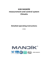
Plate heat exchanger
When selecting the heat recovery, we recommend choosing the “painted” design of the cube of recuperator. It is also
recommended to choose the vertical version of the unit with plate heat recovery. It will be avoided thus possible
condensation accumulation between the ns of the plate heat exchanger.
For vertical design this problem cannot arise.
In the plate heat exchanger section it is also possible to select the damper eliminator (if the speed is in exchanger up
to 1.5 m/s, then according to EN 13053 the eliminator can be omitted).
Door design to choose “door with hinges and handles”, for easy access for chamber remediation. “Removable panel,
fastened with clamps’ is inadmissible.
Hygienic airhandling unis

5
Hygienic airhandling unis
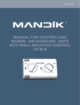
Glycol run-around recovery coils
According to Ö-NORM H6020, all heat exchanger ZZT must be equipped with a tray for condensate drain. The cooler
in the drain must have a drop eliminator (if the speed is in the exchanger up to 1.5 m/s, then according to EN 13053
the eliminator can be omitted).
It is recommended to add min. 250 mm long free chamber or atypically exchanger chamber because of the size of
special heat exchangers. This may be due to the wider range of special multi-row exchangers and the appropriate
service approach to them.

6
The fans are selected in the standard way as with standard units, but suspended on the front panel – type GR. According
to EN 13053, each ventilator chamber should be equipped with an inspection window and lighting inside the cham-
ber. This above-standard function must be selected in the window of the section itself in the “Add-ons” window.
Choose item “Sight window” and “Lighting with switch, wired”.
Floor-to-oor installations with skids are optional, but we recommend using a fan installation (GR) mounted on the
front panel of the chamber. The reason is better oor cleanability under fan installation.
FILTERS
For hygienic units it is recommended to have min. two stages of ltration. In the supply line before any recovery ac-
cording to Ö-NORM H6020, place a lter of at least M5 + F7. On exhaust min. F6.
The last ltration stage in the inlet should be placed after the last component of all elements overpressure air treat-
ment.
The last ltration stage should be replaceable from the “dirty” side of the lter. Therefore, it is appropriate before this
lter place service free chamber min. in the length of the pockets of this lter. Place inspection window a in the sec-
tion lighting according to EN 13053.
According to EN 13053, in two or more stage ltration, the rst lter must be placed in front of the fan and the second
one behind ventilator.
According to Ö-NORM H6020, it is necessary to have an analogue or digital pressure gauge for ne ltration lters.
If the unit contains a mixing chamber, according to Ö-NORM H6020, the inlet lter must be downstream air mixing
chamber.
EN 13053 species that the second stage of ltration should be placed downstream of a moisture source or conden-
sation, min. 500 mm (if it is a humidier, then the distance counts after the calculated humidication path).
According to practice and according to Ö-NORM H6020, it is recommended to place it on the outlet part of the unit
entrance ber catcher (similar to grease lter, but all-stainless).
FANS
Hygienic airhandling unis

7
Hygienic airhandling unis
COILS
Heaters
According to Ö-NORM H6020, the minimum spacing of the ns for water heaters and condensers must be min. 2.0mm.
According to EN 13053, ue gas heat exchangers are not recommended for hygienic units.
Coolers
According to Ö-NORM H6020, a minimum spacing of 2.5 mm.
According to EN 13053, there should be sucient space in front of and behind the air cooler for quality reasons clean-
ing and remediation of both exchanger, eliminator and condensate drain pan. Length of free chambers are not given,
but it should be kept in mind that the wider the unit, the longer the service should be chamber for better cleaning.
(We recommend at least 500 mm.)
According to Ö-NORM H6020 it is recommended to place the radiator under positive pressure and place it in a su-
cient position distance from lters (at least 250mm). If there is a cooler and a second ltration stage in the assembly,
it is suitable unify service chambers into one.

8
According to Ö-NORM H6020, humidiers on the principle of water circulation are not permitted. Therefore, there are
3 types of dampening that can be selected for sanitary areas:
resistance steam humidication – isothermal humidication, control accuracy is ±5% Rh,
steam humidication – isothermal humidication, dry steam is injected into the air, accuracy ±5 % Rh
electrode steam humidication – isothermal humidication due to high control inaccuracy (±10 % Rh) however, they are not
very appropriate
high-pressure spraying of water mist – adiabatic dampening, but it is necessary to have perfect water treatment (reverse os-
mosis = very expensive)
Other humidiers must be certied to be suitable for a hygienic environment Ö-NORM H6020 recommends placing the hu-
midier in a positive pressure.
Furthermore in AHUman select from the accessories in the humidier chamber service window and lighting with
higher protection.
According to Ö-NORM H6020 it is recommended to start and stop the unit for a duration of 10 minutes to prevent
condensation.
When designing a unit with both air cooler and dampening, it is recommended to place the chambers immediately
behind and behind place these air lters at a distance. For pulling out lters at the end of the unit can be used the
service door of the humidier, but it is necessary to have the lter after the calculated humidication no dampening
of the lter (according to Ö-NORM H6020).
Hygienic airhandling unis

9
Hygienic airhandling unis
SILENCERS
According to Ö-NORM H6020, perforated plate must not be used on the shock absorber slots, the sliding plate must
be smooth.
According to EN 13053, silencers, especially in the inlet, must have backdrops in hygienic design. Muers should be
installed as close to the noise source as possible. And for hygienic applications, all silencers should be located directly
in the air conditioner, no in the pipeline route.
DAMPERS
According to EN 13053 the maximum speed on the dampers (except bypass and mixing) must not exceed 8 m/s.
This standard also states that in the outdoor unit, all dampers must have opening actuators located inside the cham-
bers of the unit.
We recommend to place actuators with spring function on these dampers.

10
MIXING SETS
According to EN 13053 if it is a hygienic unit in outdoor version and if it contains water coil, then the mixing junction
must be located in the unit.
We recommend selecting “empty space for mixing junction” in the heat exchanger entry form.
BASE FRAME
It is recommended to place a base frame with adjustable feet and height of 300 mm below the unit so that there is
sucient height for the condensate drain and the feet to adjust to the unit perfect horizontal position.
Hygienic airhandling unis

11
Hygienic airhandling unis Typy použitých vestaveb
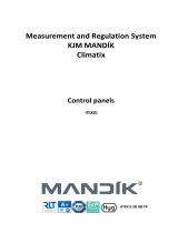
Examples how should be assembled hygienic units:
Outdoor unit with plate heat recovery, water heating and cooling, humidication, two-stage ltration and silencers
on room side.
Indoor unit with plate heat recovery, water heating and cooling and two-stage ltration.
Indoor unit with glycol recovery, water heating and cooling and two-stage ltration.

MANDÍK, a. s.
Dobříšská 550
267 24 HOSTOMICE
Czech Republic
Tel.: +420 311 706 706
Fax: +420 311 584 810
E-mail: [email protected]
www.mandik.cz
Date of publication: December 2019
/