
MANDÍK CPV Installation, commissioning, and maintenance
IZU 06/2021 MANDÍK, a.s., www.mandik.cz
R
1
CPV Compact Air Handling Units
INSTALLATION
COMMISSIONING
MAINTENANCE
R

MANDÍK CPV Installation, commissioning, and maintenance
IZU 06/2021 MANDÍK, a.s., www.mandik.cz
R
2
Contact:
MANDÍK, a.s.
Dobříšská 550
267 24 Hostomice
Czech Republic
tel: +420 311 706 706
fax: +420 311 584 810
email: [email protected]
service department email: [email protected]
© Copyright MANDÍK, a.s. 2021. Subject to change.

MANDÍK CPV Installation, commissioning, and maintenance
IZU 06/2021 MANDÍK, a.s., www.mandik.cz
R
3
CONTENTS
1 GENERAL ......................................................................................................................... 5
2 RELATED DOCUMENTS ................................................................................................... 6
3 GENERAL INFORMATION ................................................................................................ 7
3.1 UNIT IDENTIFICATION ................................................................................................... 7
3.2 DIMENSIONS OF THE UNIT ............................................................................................ 8
3.3 CONNECTION DIMENSIONS .......................................................................................... 8
4 SAFETY ............................................................................................................................ 9
5 HANDLING, TRANSPORT AND STORAGE ...................................................................... 10
6 ASSEMBLY AND INSTALLATION .................................................................................... 12
6.1 GENERAL ...................................................................................................................... 12
6.2 GENERAL STIPULATIONS REGARDING UNIT PLACEMENT ........................................... 13
6.3 PLACING UNITS ON FLOORS ........................................................................................ 13
6.4 GENERAL INSTRUCTIONS FOR ASSEMBLING THE UNIT .............................................. 13
6.5 CONNECTING THE UNIT TO HVAC DUCTWORK .......................................................... 14
6.6 CONDENSATE DRAIN TRAP CONNECTION .................................................................. 14
6.7 HOT / COLD WATER COIL CONNECTIONS ................................................................... 15
6.8 ELECTRICAL CONNECTIONS ......................................................................................... 17
7 ACTIVITIES PRIOR TO COMMISSIONING ...................................................................... 19
7.1 GENERAL ...................................................................................................................... 19
7.2 INSPECTING THE UNIT PRIOR TO INITIAL START-UP ................................................... 20
7.3 CONFIGURATION OF THE CONTROL SYSTEM FOR UNIT START-UP ............................ 22
8 COMMISSIONING ......................................................................................................... 23
8.1 ACTIVITIES PRIOR TO INITIAL START-UP...................................................................... 23
8.2 ACTIVITIES DURING INITIAL START-UP ........................................................................ 23
8.3 INITIAL PLACEMENT OF THE UNIT INTO SERVICE ....................................................... 24
8.4 CONTROLLING AIR OUTPUT FROM THE UNIT ............................................................. 24
8.5 OPERATOR TRAINING AND HANDOVER OF THE UNIT ................................................ 26
9 OPEATION AND MAINTENANCE ................................................................................... 28
9.1 DESCRIPTION OF THE UNIT – COMPONENTS .............................................................. 28
9.2 DESCRPTION OF THE UNIT – CONTROL SYSTEM ......................................................... 29
9.3 GENERAL OPERATION AND MAINTENANCE ............................................................... 30

MANDÍK CPV Installation, commissioning, and maintenance
IZU 06/2021 MANDÍK, a.s., www.mandik.cz
R
4
9.4 MAINTENANCE AND SERVICE INTERVALS ................................................................... 31
9.5 GENERAL OPERATION AND MAINTENANCE OF THE UNIT .......................................... 35
9.6 FANS ............................................................................................................................ 36
9.7 FILTERS ....................................................................................................................... 36
9.8 DAMPERS, FLEXIBLE ELEMENTS .................................................................................. 37
9.9 HOT WATER COIL, COLD WATER COIL ........................................................................ 38
9.10 CONDENSER COIL, DIRECT EVAPORATOR COIL ........................................................... 38
9.11 PLATE RECUPERATOR ................................................................................................. 39
9.12 ELECTRIC HEATER ........................................................................................................ 39
ANNEX A. QUICK FAN ADJUSTMENT - POL871 HMI CONTROLLER ..................................... 44
ANNEX B. QUICK STARTING THE UNIT – WEB / POL871 HMI CONTROLLER ....................... 46
ANNEX C. QUICK STARTING THE UNIT – POL822 ROOM UNIT ............................................ 47
ANNEX D. MAINS CONNECTION – HOT WATER HEATING ................................................... 50
ANNEX E. MAINS CONNECTION – ELECTRIC HEATING ........................................................ 51
ANNEX F. PERIPHERALS – CO2 SENSOR, POL822 ROOM UNIT, PIPING TEMPERATURE SENSOR
52

MANDÍK CPV Installation, commissioning, and maintenance
IZU 06/2021 MANDÍK, a.s., www.mandik.cz
R
5
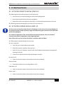
1 GENERAL
This manual uses graphics and symbols to highlight specific details. They include:
This symbol indicates a potentially hazardous situation and an imminent health or
safety hazard to personnel, the unit, or its components.
This symbol indicates an electrocution hazard.
This symbol indicates an important detail related to proper installation,
commissioning or maintenance of the unit or its components. It may also
indicate a suggestion or a note concerning installation, commissioning, or
maintenance.
This manual contains the procedures for proper installation, commissioning, and maintenance
of the CPV line of compact air handling units from MANDÍK.
Review these instructions prior to beginning any activity involving the unit and adhere to
them. Adherence to these instructions is a prerequisite for the proper operation, and
functionality, and to comply with warranty conditions. The manufacturer is not liable and the
user bears all risks for any damage resulting from improper use.
This manual is intended for personnel with valid authorisation and licenses to conduct service
work on ventilation and air handling units.
CPV air handling units are designed for central distribution and conditioning of air in
ventilation and air-conditioning systems. Air conveyed by the unit must first be filtered to
remove physical and gaseous impurities that could foul the installed components or corrode
the materials used in the construction of the unit. Units are designed for normal
environments without an explosion hazard with an ambient temperature of -30 °C to +40 °C,
for circulating air within normal humidity levels (they are not designed for damp air service,
such as in pool facilities, etc.). Any other use is prohibited.
Any arbitrary modifications to the unit, such as expansions, not previously approved by
MANDÍK, a.s., shall render the provided warranty, along with the guarantee of safe use and
operation, null and void.

MANDÍK CPV Installation, commissioning, and maintenance
IZU 06/2021 MANDÍK, a.s., www.mandik.cz
R
6
2 RELATED DOCUMENTS
The following documents are attached to every delivered unit:
• Warranty sheet
• Installation, operation and maintenance manual
• Technical specifications of the unit
• Declaration of conformity
• List of fasteners and other materials
• Drawing documentation for the control system
• Manual for installation and operation of the control system
Other documents online at www.mandik.cz, in the Production Line / Air Handling units /
Mandík Compact Air Handling Units:
• Instructions for control and configuration of the SIEMENS Climatix controller
• Instructions for control and configuration of the SIEMENS - POL822 room unit with
controls

MANDÍK CPV Installation, commissioning, and maintenance
IZU 06/2021 MANDÍK, a.s., www.mandik.cz
R
7
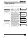
3 GENERAL INFORMATION
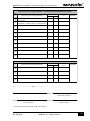
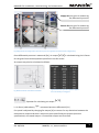
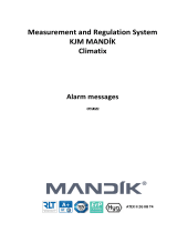
3.1 UNIT IDENTIFICATION
Every unit is equipped with a nameplate that specifies it’s basic technical parameters.
Nameplates are a total of two, separately for the supply and exhaust part.
Unit type size
Order number
Production number
Construction certificate of
the authorised person
Filter information
- Type, pressure losses,
composition
Determination of the
nameplate for SUPPLY /
EXHAUST.
Nominal air flow
Recuperator information
- pressure losses
Cooler Information
- power, flow, medium
Heater Information
- power, flow, medium
Pressure loss for damper
in the end wall
Fan information
- type, pressure losses
(external, total), K-factor.
- operation/nominal
revolutions
- nominal values for
power, voltage, current

MANDÍK CPV Installation, commissioning, and maintenance
IZU 06/2021 MANDÍK, a.s., www.mandik.cz
R
8
3.2 DIMENSIONS OF THE UNIT
The dimensions of the unit are calculated dynamically in the software per the specific order in
steps of 1 mm. The specific dimensions of selected units are provided in the relevant technical
specifications. The maximum production dimensions (specified for the external housing) are:
length x width x height = 3880 x 2000 x 2200 mm.
3.3 CONNECTION DIMENSIONS
A unit may have round or square duct connections per specifications.
Air duct connection dimensions are calculated dynamically in the software per the specific
order in steps of 10 mm. The specific connection dimensions of selected units are provided in
the relevant technical specifications.

MANDÍK CPV Installation, commissioning, and maintenance
IZU 06/2021 MANDÍK, a.s., www.mandik.cz
R
9
4 SAFETY
The safety instructions provided herein must be followed when using the unit.
• All valid standards, safety regulations and generally accepted technical rules must be
followed during assembly, wiring, commissioning, repairs and maintenance of the
unit!
• Only natural persons or legal entities with valid authorisation are permitted to
conduct assembly of the unit, including electrical wiring, commissioning, repairs,
maintenance and operation.
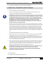
The following general instructions are considered absolutely necessary. Additional
recommended instructions are provided in detail in the section covering assembly,
commissioning, and maintenance.
The following points must be met before start-up of the unit:
• All service panels and doors on the unit must be secured and fastened.
• Ensure that no one is inside the unit or in any other hazardous area around the unit.
• Commissioning and maintenance instructions are provided in the corresponding
sections of this manual.
The unit must not be operated under these conditions:
• The unit is installed in an environment where an explosive atmosphere may occur (does
not apply to ATEX units)
• The unit is installed in close proximity to magnetic fields
• The air entering the unit contains aggressive gases or chemicals or the air temperature
is below -30°C or higher than +50°C, or the return air humidity is excessively high (the
unit is not designed for damp air service, such as in pool facilities, etc.)
Access inside the equipment and conducting any work on the equipment are prohibited until
the following are met:
• The unit must be disconnected from power.
• All rotating parts (fans, etc.) must be stopped
• The unit must be locked out to prevent accidental start--up (e.g. at the service switch)
• Heat exchangers and hydraulic system components must be cooled down to the
ambient temperature, i.e. a maximum surface temperature of +40°C
• Pressure in all pressurised systems must be equalised to the ambient pressure
• The operator must be equipped with suitable protective equipment

MANDÍK CPV Installation, commissioning, and maintenance
IZU 06/2021 MANDÍK, a.s., www.mandik.cz
R
10
• No explosive atmosphere is present inside the equipment.
5 HANDLING, TRANSPORT AND STORAGE
• Units are delivered in compact assemblies.
• The units are wrapped in a plastic film, and are placed and packed on pallets. The
specific type of packaging may be agreed upon individually
• ATTENTION: the plastic film is protected by shipping packaging to protect the chamber
during transport and must not be used for long-term storage of the chamber. Changes
in temperature during transport may result in water vapour condensing inside the
packaging and create suitable conditions to result in corrosion of the materials used in
the chambers (e.g. white corrosion on galvanised components). The transport
packaging must be removed immediately upon delivery to ensure air can enter the
chambers and they can dry appropriately
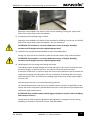
• During transport and relocation, the units may only be moved by forklift or using lifting
straps and corresponding safety regulations must be followed (ČSN ISO 8792). Units may
only be lifted from below. When lifting by crane, use straps under the unit; for larger
units, these straps require a spacer from above, or additional reinforcement at points
where the strap could deform the chamber. When transporting by forklift, support the
chamber along the entire width of the chamber to prevent damage to the bottom of the
unit.
Permitting handling activities are illustrated below.
• Upon receipt, the unit must be inspected to ensure it has been delivered in the agreed
configuration and scope, and to ensure it was not damaged during transport. If
damaged during transport, the receiving party shall record the scope of such damage on
the carrier’s delivery note. Failure to follow this procedure may result in denial of any
claim involving damage during transport.
• Units must be stored in dry, and clean covered premises, protected from rain and snow,
and in which the ambient temperature does not drop below +5 °C; they must also be
protected from physical damage, contamination and corrosion caused by persistent
exposure to condensed water vapour on the surface of the unit.
• ATTENTION: If the equipment is suspended during transport, a safe distance must be
maintained from the load and never enter the area under a load. Keep the
acceleration and speed of lifting within safety limits. Never leave the equipment
suspended for longer than necessary!
Permitted handling:
1) Preparation and handling using a pallet truck

MANDÍK CPV Installation, commissioning, and maintenance
IZU 06/2021 MANDÍK, a.s., www.mandik.cz
R
11
Openings are provided in the frame of the units for handling. During use, pallet truck
forks must remain fully under the chamber.
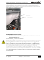
2) Preparation and handling using a forklift
Openings are provided in the frame of the chamber for handling. During use, the forklift
forks must remain fully under the chamber, see the illustration.
ATTENTION: The chamber is not evenly balanced in terms of weight. Handling
activities and lift heights must be adapted appropriately!
3) Chambers are transported and handled on non-returnable pallets
During use, the forks on the forklift or pallet truck must remain fully under the pallet.
ATTENTION: The chamber is not evenly balanced in terms of weight. Handling
activities and lift heights must be adapted appropriately!
4) Handling with the unit using steel tubing and straps
The tubing must be passed through the round openings in the corner of the frame over
the entire length, or width of the unit. The tubes must extend past the straps
a minimum of 100 mm. It is best to equip the ends of the tubes with clips to prevent the
straps from slipping. Use tubing 40 to 45 mm in diameter. Use tubing with a minimum
wall thickness of 5 mm. The minimum clamping angle of the strap to the upper edge of
the unit is 50°.
Only transport the unit in its horizontal working position.
To prevent deformation in the unit at the locations where pressure is applied by straps,
ensure the straps are properly spaced above the unit or these points are protected with
sufficiently rigid reinforcement.
ATTENTION: Only suitable and permitted rigging equipment may be used for handling
and transport of units!
Comply with all valid technical regulations and legislation in the given country during
handling. For example: ČSN EN 13 155+A2, ČSN ISO 12480-1.

MANDÍK CPV Installation, commissioning, and maintenance
IZU 06/2021 MANDÍK, a.s., www.mandik.cz
R
12
6 ASSEMBLY AND INSTALLATION
6.1 GENERAL
• Only authorised personnel may assemble units. Personnel conducting assembly must
comply with all valid technical regulations and legislation in the given country. For
example: ČSN EN 45004, Act 174/68 Coll.
• Wiring and earthing of the electrical devices, electric motor and the entire electrical
installation must comply in particular with ČSN 33 2190, ČSN 33 2000-4-41, ČSN 33
2000-5-51, ČSN 33 2000-5-54, and other valid regulations for the given environment to
ensure safe operation.
• The unit and its accessories may only be placed into use by an authorised and trained
specialised technician who is familiar with the equipment and the related hazards
• Before assembly of the unit, a check must be performed to ensure the site is prepared,
along with the mains voltage, temperature and pressure of the heating medium, and
the completeness and condition of all parts of the unit
• Any defects must be remedied prior to assembly of the unit
• The unit and is accessories may only be connected to 230 V / 400 V, 50 Hz mains.
• Access must be maintained to the wiring panel to which the systems are connected.
Power components (circuit breakers, contactors, switches, etc.) must be clearly labelled
in the wiring panel with the number of the equipment per the HVAC project!
• We recommend a representative of the assembling organisation and the user attend
operator training.
• The unit cannot perform any structural functions, such as supporting the static load of
the building and related elements for the operation of the unit, or otherwise support
footbridges and wiring, electrical switchboards, etc., except for any deviations
permitted in consultation with Mandík, a. s. Failure to comply will void the warranty
provided by Mandík, a. s.
• Wearing protective gloves is recommended during assembly and handling of the unit.
• During handling and lifting, the units may only be moved by forklift or using lifting straps
and corresponding safety regulations must be followed. The unit must not be raised and
moved above personnel! See Subsection 5 HANDLING, TRANSPORT AND STORAGE
• All supports and braces delivered with the unit for transport must be removed prior to
assembly
• Total fan pressure is sized for the design external pressure losses upstream and
downstream of the fan; see the technical specifications of the unit. The ductwork
installation must be adapted accordingly, and without additional pressure losses that

MANDÍK CPV Installation, commissioning, and maintenance
IZU 06/2021 MANDÍK, a.s., www.mandik.cz
R
13
could result in a higher controlled working point for the fan and higher electric motor
power usage.
6.2 GENERAL STIPULATIONS REGARDING UNIT PLACEMENT
• The minimum space for basic maintenance and service is dependent upon the width of
the doors as specified in the technical specifications for the given unit, or a minimum of
600 mm
• The minimum space required for repairs and the replacement of devices is the width of
the unit + 200 mm
• The minimum spacing between hot items and the unit is 200 mm.
• Units for outdoor installation must be sufficiently fastened to their base as required for
the expected climactic conditions and exposure.
6.3 PLACING UNITS ON FLOORS
• Permitted handling of units for installation is specified in Subsection 4.
• The units must be installed on solid, level floors to which they can be rigidly fastened. It
is advisable to install a dampening material (e.g. rubber, cork) under the frame of the
unit at the place of installation
• The maximum permitted deviation from the horizontal is 0.5% (0.3°)
• The unit must be installed at a sufficient height above the floor / ground to provide
sufficient trap height on chambers equipped with condensate drains, see the Subsection
6.6 TRAP ASSEMBLY.
• Failure to ensure sufficient stability or levelness of the surface may degrade the
functionality of the unit and even cause damage, including misalignment of the fan
impeller relative to the inlet fairing, the inability to open the chamber doors, etc.!
6.4 GENERAL INSTRUCTIONS FOR ASSEMBLING THE UNIT
Perform the following before installing the unit:
• Check the site of installation of the unit and the stability of all underlying surfaces:
the unit is supported over its entire footprint, the unit is installed in a level position
within the maximum allowed deviation, and the dampening material is installed
between the unit and the underlying surface or steel structure.
• All packaging film is removed from the unit
• All additional items have been removed from the unit (cardboard boxes with accessories
or control circuitry and other accessories) and placed in a secure and dry place

MANDÍK CPV Installation, commissioning, and maintenance
IZU 06/2021 MANDÍK, a.s., www.mandik.cz
R
14
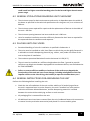
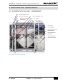
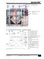
6.5 CONNECTING THE UNIT TO HVAC DUCTWORK
The unit may only be connected to square ducts using flexible elements installed on every
supply / return on the unit (to prevent the transmission of vibration), or to round ducts using
round ports with gaskets that are installed on every supply / return on the unit.
The HVAC ductwork must be connected without tension, i.e. so that the weight of the
ductwork itself does not load the flexible element and the unit.
Flanged HVAC ductwork connections and flexible elements must be properly sealed.
Specification of the supply / return connections on the unit:
Fig. 1 outlets, right-hand design of CPV unit
Fig 2 outlets, left-hand design of CPV unit
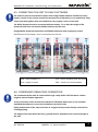
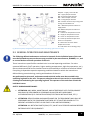
6.6 CONDENSATE DRAIN TRAP CONNECTION
The condensate drain must be connected through a trap with a sufficient water column
height to ensure flawless operation.
A trap connection under vacuum must always be filled with water prior to use and after
extended shut-downs to ensure the condensate can drain freely.
Piping downstream of the trap must have an air gap and may not be directly connected to
sewerage piping.
The height of the unit above the floor / ground must be adapted to the necessary height of
the trap.
ODA – fresh outdoor air ETA – return (exhaust) from the space
SUP – supply to space EHA – exhaust air to atmosphere

MANDÍK CPV Installation, commissioning, and maintenance
IZU 06/2021 MANDÍK, a.s., www.mandik.cz
R
15
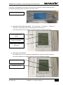
When a trap is installed outdoors, the piping system must be tempered, i.e. using an
electrical heating cable.
Proper configuration of trap height per the pressure values is as follows:
Fig. 3 Vacuum trap with ball HL136NGG
May be used at vacuum up to 2300 Pa.
H=P/10 (P = value of the pressure specified in the technical specifications of the unit
[Pa])
Fig 4 Trap connection point
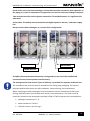
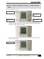
6.7 HOT / COLD WATER COIL CONNECTIONS
All piping must be anchored separately from the heat exchangers. Piping systems conveying
the working media may not exert pressure due to their weight of expansion forces on the
TRAP CONNECTION

MANDÍK CPV Installation, commissioning, and maintenance
IZU 06/2021 MANDÍK, a.s., www.mandik.cz
R
16
blocks of the unit or the heat exchangers. Connections must be executed so that expansion of
the piping as a result of temperature changes does not result in excessive loading of the ports.
Two wrenches must be used to tighten connections. Thread deformation is a significant risk
otherwise!
A vent valve, if installed, must be located at the highest point on the hot / cold water supply
line.
Always connect heat exchangers in a counter-flow configuration!
Fig 5 Right-hand unit configuration
Fig 6 Left-hand unit configuration
A capillary freeze-protection thermostat is integrated into the unit, fully installed and
connected to the control system from the factory.
The mixing loop for heat control, if part of delivery, is provided in a separate cardboard box.
The installation and service manual is attached to the mixing loop packaging. The manual
provides detailed information on safe installation, commissioning, and maintenance.
Water supplying the heat exchangers must be treated to remove contaminants that cause
fouling, especially those that corrode steel and cast iron components. The water must be
chemically treated to the parameters specified in ČSN 07 7401 to prevent this contamination.
• Hydrogen exponent pH 7 - 9.
• Water hardness 1.0 mval.l-1.
• Chloride content, max. 30 mg.l-1.
MEDIA INPUT
MEDIA OUTPUT
MEDIA INPUT
MEDIA OUTPUT

MANDÍK CPV Installation, commissioning, and maintenance
IZU 06/2021 MANDÍK, a.s., www.mandik.cz
R
17
Phosphate content converted to P2O5, min. 15 mg.l-1.
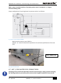
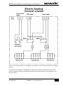
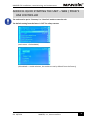
6.8 ELECTRICAL CONNECTIONS
Any intervention into electrical panels or connection of the provided components may only
be performed by personnel with professional qualifications under the valid legislation in the
country of installation of the equipment!
Individual components of the unit are typically wired from the factory to the terminals of the
controller and tests (fans, sensors, actuators, thermostats, manostats, electric heater, etc.).
It is only necessary to connect the provided peripheral devices (the POL822 room unit, Touch
Panel, CO2 sensor, piping temperature sensor, control loop, etc.) All connection schematics
are provided in the design documentation package for the unit, “MANDÍK Air Handler
Controls”.
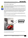
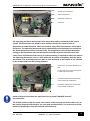
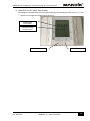
The mains connection for the unit is typically provided via a receptacle installed right next to
the main switch. The type of receptacle is specified in the technical specifications of the unit,
and the manner of installation is illustrated below.
If the unit is not equipped with a main power receptacle from the factory and a separate mains
connection is required, the threaded cable gland next to the main switch is used for this purpose.
Fig 7 Main connection for the unit and main switch
The provided threaded glands located right next to the main switch are used to connect the
provided peripherals to the terminal block.
MAINS CONNECTION
MAIN SWITCH

MANDÍK CPV Installation, commissioning, and maintenance
IZU 06/2021 MANDÍK, a.s., www.mandik.cz
R
18
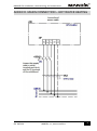
The mains connection schematic for models with a hot water coil is provided in Annex D.
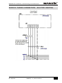
The mains connection schematic for models with an electric heater is provided in Annex E.
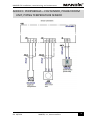
The connection schematic for peripherals: the CO2 sensor, POL822 room unit, and exterior
outdoor air temperature sensor, is provided in Annex F.

MANDÍK CPV Installation, commissioning, and maintenance
IZU 06/2021 MANDÍK, a.s., www.mandik.cz
R
19
7 ACTIVITIES PRIOR TO COMMISSIONING
7.1 GENERAL
• The unit may only be commissioned by instructed and trained personnel and with full
adherence to applicable safety regulations and standards.
• Prior to commissioning, it is necessary to complete all the previous steps in the
installation instructions.
• Prior to commissioning, the individual steps below must be completed and recorded
in a suitable protocol that is then attached to the operating documentation and a copy
of which must be sent by post to MANDÍK, a.s. or via email to our service centre at
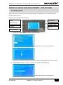
• The following paragraph with instructions may be followed step-by-step when
inspecting the individual parts of the unit and which is created as a protocol and may
be used as a suitable guide for the commissioning process.

MANDÍK CPV Installation, commissioning, and maintenance
IZU 06/2021 MANDÍK, a.s., www.mandik.cz
R
20
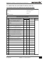
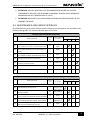
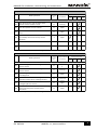
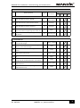
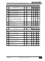
7.2 INSPECTING THE UNIT PRIOR TO INITIAL START-UP
LIST OF SERVICING OPERATIONS PRIOR COMMISSIONING AIR-CONDITIONING UNIT MANDÍK
Order number: User:
Date: Commissioning party:
Project name: Serial number:
Address: Position:
Date of first start-up:
YES NO
1.01.
1.02.
1.03.
1.04.
1.05.
1.06.
1.07.
1.08.
1.09.
1.10.
1.11.
1.12.
1.13.
1.14.
1.15.
1.16.
1.17.
1.18.
1.19.
Check the total tightness of the unit – visually
(the door, service panels, fixed panels, etc.).
Opera
tion
Description of servicing operation
Completion of operation
Check the cleanness of the chamber interior –
without foreign bodies and construction
Check closing of the unit – the door, service
panels.
Check the mounting of the roof on outdoor
units acc. to installation instructions.
Check the tightness of chamber connections –
visually, acc. to installation instructions.
OPERATIONS FOR THE UNIT IN GENERAL
Check the seating order of the chambers within
the unit acc. to the documentation.
Check each chamber for external or internal
damage.
Check connecting eccentric pieces between the
chambers – in the “tightened” position.
Check the seating of the unit – on the
floor/ceiling acc. to installation instructions.
Measured or set
value *
Comment
Check the connection of HVAC piping to the
damping inserts acc. to installation
Check the legibility and cleanness of
manufacturing and safety plates. Clean if
Page is loading ...
Page is loading ...
Page is loading ...
Page is loading ...
Page is loading ...
Page is loading ...
Page is loading ...
Page is loading ...
Page is loading ...
Page is loading ...
Page is loading ...
Page is loading ...
Page is loading ...
Page is loading ...
Page is loading ...
Page is loading ...
Page is loading ...
Page is loading ...
Page is loading ...
Page is loading ...
Page is loading ...
Page is loading ...
Page is loading ...
Page is loading ...
Page is loading ...
Page is loading ...
Page is loading ...
Page is loading ...
Page is loading ...
Page is loading ...
Page is loading ...
Page is loading ...
-
 1
1
-
 2
2
-
 3
3
-
 4
4
-
 5
5
-
 6
6
-
 7
7
-
 8
8
-
 9
9
-
 10
10
-
 11
11
-
 12
12
-
 13
13
-
 14
14
-
 15
15
-
 16
16
-
 17
17
-
 18
18
-
 19
19
-
 20
20
-
 21
21
-
 22
22
-
 23
23
-
 24
24
-
 25
25
-
 26
26
-
 27
27
-
 28
28
-
 29
29
-
 30
30
-
 31
31
-
 32
32
-
 33
33
-
 34
34
-
 35
35
-
 36
36
-
 37
37
-
 38
38
-
 39
39
-
 40
40
-
 41
41
-
 42
42
-
 43
43
-
 44
44
-
 45
45
-
 46
46
-
 47
47
-
 48
48
-
 49
49
-
 50
50
-
 51
51
-
 52
52


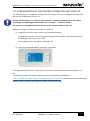
Ask a question and I''ll find the answer in the document
Finding information in a document is now easier with AI
Related papers
-
 Mandik Control system User guide
-
 Mandik Control system User guide
-
 Mandik Control system – Control panels User guide
-
 Mandik Control system Operating instructions
-
 Mandik AHU-HYG User guide
-
 Mandik AHU – Parameterisation from POL822 Room Device User guide
-
 Mandik Control system – Alarm messages User guide
-
 Mandik DHS control box User guide
-
 Mandik Control system Owner's manual
-
 Mandik MMS control box User guide


Other documents
-
CIAT CLIMACIAT AIRTECH User manual
-
Hauck Rad Operating instructions
-
Eclipse CROSS FLOW Datasheet
-
-
Ruck DVL 450 EC RK 01 Owner's manual
-
Dimplex AWP 300 LW Datasheet
-
Festo CPV18-GE-FB-8 Electronic Manual
-
Komfovent Domekt R 200 VSO C8 Installation guide
-
Viadrus G 700 Operation and Installation Manual
-