Page is loading ...

Measurement and Regulation System
KJM MANDÍK
Climatix
Control panels
07/2022

KJM MANDÍK – Control Panels
M&R KJMOP 07/2022 MANDÍK, a.s., www.mandik.cz
2
Contact:
MANDÍK, a.s.
Dobříšská 550
267 24 Hostomice
Czech Republic
Phone: +420 311 706 706
Fax: +420 311 584 810
E-mail: [email protected]
service department email: [email protected]
This manual is an integral part of the technical conditions TPM 088/12 of MANDÍK AC units. The
latest versions of the documents are available at www.mandik.cz
© Copyright MANDÍK, a.s. 2022. Subject to change.

KJM MANDÍK – Control Panels
M&R KJMOP 07/2022 MANDÍK, a.s., www.mandik.cz
3
1 Introduction ................................................................................................ 4
2 Integrated HMI control unit ......................................................................... 4
3 HMI-DM control unit ................................................................................... 4
4 HMI-TM control unit .................................................................................... 5
5 HMI@Web control ....................................................................................... 6
6 Function buttons of the integrated HMI, HMI-TM/DM or HMI@Web .......... 8
7 Room unit POL822.60 .................................................................................. 9
8 QMX3 series room devices ........................................................................ 10
9 HMI/ROx, HMI/SPx, CP-M-B, and WRF04 controllers ................................. 11
10 OP41 and OP70 controllers with Modbus communication ......................... 14
11 Colour touch panel .................................................................................... 15

KJM MANDÍK – Control Panels
M&R KJMOP 07/2022 MANDÍK, a.s., www.mandik.cz
4
1 Introduction
The HMI control panels of the Climatix controller are designed to inform the user about
the operating status of the MANDÍK AC unit, to configure the unit, enter or select desired values
or states, and for service purposes. They consist of a backlit LCD display and function keys. There
are three versions of HMI control panels, depending on their desired location.
A separate type of HMI level control is HMI@Web, which allows full control of the AC unit
via a web browser.
For control, room instruments, controllers and touchscreens with different types of
communication can still be used, which are mainly intended for user changes.
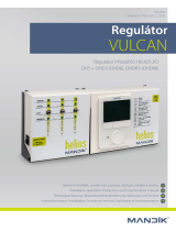
2 Integrated HMI control unit
The integrated or fixed design of the control panel with display (Fig.1) is firmly connected
to the controller. It contains four buttons, one of which is a navigation button, and a four-line
display. It is designed for control and service purposes. This does not apply to all the types of
Climatix controllers.
Fig. 1
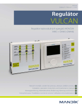
3 HMI-DM control unit
The portable version (Fig. 2) has the type designation HMI-DM and can be used to control
multiple AC units or it can be fixed on a wall in the conditioned space. It contains four buttons,
one of which is a navigation button, and an eight-line display. It also includes a temperature
sensor that can replace the room temperature sensor if the controller is placed in the conditioned
space. The operation of the unit is indicated by a green LED in the info button. A fault is indicated
by a flashing red LED in the alarm button. This version of the control unit can be located up to

KJM MANDÍK – Control Panels
M&R KJMOP 07/2022 MANDÍK, a.s., www.mandik.cz
5
700 m from the M&R controller of the AC unit and is connected by a twisted pair connection. The
control unit is designed for control and service purposes. The HMI-DM control unit comes with a
mounting sheet.
Fig. 2
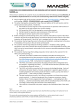
4 HMI-TM control unit
The version designed for the metal switchboard door (Fig. 3) has the type designation
HMI-TM and has two variants: version for fixed installation in the metal switchboard door or a
version for free attachment with magnetic pad. It contains six buttons and a blue backlit eight-
line display. The operation of the unit is indicated by a green LED in the info button. A fault is
indicated by a flashing red LED in the alarm button. The control unit is designed for control and
service purposes. The HMI-TM control unit comes with a mounting sheet.
Fig. 3

KJM MANDÍK – Control Panels
M&R KJMOP 07/2022 MANDÍK, a.s., www.mandik.cz
6
5 HMI@Web control
The HMI@Web control (Fig. 4) is used to control the AC unit via a PC equipped with a web
browser and Ethernet network card.
The control is similar to the controller display or the HMI-TM and HMI-DM control units.
The possibility to change a displayed value is indicated by a red arrow at the end of the line. When
the cursor clicks on this arrow, the input screen is displayed and after changing the value from
the keyboard, the change is saved by clicking on the Save button. The green arrow at the end of
the line indicates the option to enter a lower menu level, which is again done by clicking on this
arrow. To return from the menu, click on the arrow on the first line with the menu title or on the
icon labelled ESC. To view the history or current alarms, click on the icon with the bell picture.
Click on the icon labelled ApplicationInfo to display the home screen. The icon labelled OK has
no function by default.
Access via a web browser is conditional on entering the correct controller address in the
browser command line and then entering the correct login credentials, name, and password. If
the login window does not appear, then the controller address was not entered correctly. The
factory default setting of the controller address for HMI@Web access is as follows:
▪ IP-address: 192.168.1.42
▪ SubnetMask: 255.255.255.0
▪ DefaultGateway: 192.168.1.254
▪ DHCP Passive
Change this setting by entering the password in the menu SystemObjects
Communication
TCP/IP. To activate the change, the change must be made using item AfterModificationOfValue
RestartRequired!
In the menu SystemObjects
Communication
TCP/IP
Advanced it is also possible to change
the login data for HMI@Web via a web browser. The factory default setting is:
▪ UserName: KJWEB
▪ Password: SBT!Mandik
The manufacturer recommends changing the HMI@Web username and password using one of
the control units!

KJM MANDÍK – Control Panels
M&R KJMOP 07/2022 MANDÍK, a.s., www.mandik.cz
7
Fig. 4
The PC can be connected directly to the controller via an Ethernet cable, connected
between the PC network card and the controller connector marked Ethernet. The maximum
cable length can be up to 100 m, depending on the environment. If you are not a PC
administrator, please entrust the necessary changes to the controller IP address and PC settings
to your PC administrator.
A PC can also be connected to the controller via LAN. The manufacturer also recommends
that you entrust the necessary changes to the controller IP address and PC settings to the
network administrator.
The PC can also be connected to the controller via the Internet from any PC, tablet or
mobile phone. The integration of the HMI@Web controller into the local network must be carried
out by the network administrator!
The recommended web browsers are Google Chrome and Firefox, and for good
communication with the HMI@Web controller, the following parameters must be set:
▪ JavaScript support enabled
▪ Cookies enabled
▪ Check for newer versions every time you visit the site
It is recommended to entrust the necessary changes in the web browser settings to the PC or
network administrator.
In the HMI@Web control, up to five analogue values (temperatures, heating outputs,
cooling outputs, etc.) can be displayed graphically in real time by clicking the mouse on the

KJM MANDÍK – Control Panels
M&R KJMOP 07/2022 MANDÍK, a.s., www.mandik.cz
8
desired value (Fig. 57). The graph can be stopped/stopped by clicking on the Stop/Start Trending
button. The graph can be shown or hidden by clicking the View/Hidden Trend button.
Fig. 5
6 Function buttons of the integrated HMI, HMI-TM/DM or
HMI@Web
The buttons of the HMI control panel are used to control and configure the parameters
of the Climatix controller for the MANDIK AC unit. Their description and functions are listed in
the following table.
The position of the cursor in the menu is indicated by an inverse display. The possibility
to change the displayed value is indicated by the inverse display of the entire line. By pressing
the OK or Enter button, this value can be changed. Changing the value does not save it in the
controller's memory. The value must be saved by pressing the OK or Enter button. The arrow at
the end of the line indicates the possibility to enter a lower menu level, which is again done by
pressing the OK or Enter button.
If the HMI control panel is designed to be portable, then when the control panel
connector is plugged into the Climatix controller in the rack, the home screen is loaded.
In some applications, the control panel is fixed in the rack and there is no need to connect
the control panel to the controller. The home screen will then appear when the controller's
supply voltage is switched on.

KJM MANDÍK – Control Panels
M&R KJMOP 07/2022 MANDÍK, a.s., www.mandik.cz
9
7 Room unit POL822.60
A separate device for controlling the AC unit is the POL822.60 room unit (Fig.6), which is
intended for user operation only and is used in combination with the previous control methods
mentioned above or in combination with computer control via a web interface.
Fig. 6
Button
Description
INFO
Return one level up in the menu or to the top of the screen. For
alarms, return to the previous screen.
ESC
Return one level up in the menu or to the top of the screen. For
alarms, return to the previous screen.
The alarm management screen is loaded.
OK
The rotary knob combines the selection function, confirmation
function, and value change function. Rotate the button to scroll
through the menu or change the value. Pressing the button enters
the selected menu item or confirms the desired value change. Not
available in the HMI–TM version. In HMI@Web, this icon is not
functional.
Enter
This button is only included in the HMI-TM version and is used to
confirm the selected menu or to confirm a value change.
Up, Down
These two buttons are only part of the HMI-TM design and are only
used to scroll through a menu or change a value.
Table 1 – Function buttons of the HMI panels

KJM MANDÍK – Control Panels
M&R KJMOP 07/2022 MANDÍK, a.s., www.mandik.cz
10
It contains six buttons, one of which is a navigation button, and LCD display to show room
or selected temperature, operating modes, fan speed, current time, fault indication, etc. The
room unit can be located up to 700 m away from the M&R controller of the AC unit and is
connected by a twisted pair connection. Its description and method of use is described in a
separate manual. The room unit is supplied with its installation sheet. The controller is described
in detail in a separate Manual for controlling the Mandík AC unit from the POL822 device located
on the website of Mandík a.s.
8 QMX3 series room devices
Other devices for controlling AC units are the QMX3 series room devices from Siemens
(Fig. 7) with KNX communication (S-mode).
Fig. 7
The QMX3 series can be used as control units with room temperature, relative humidity, and CO2
measuring or as stand-alone room sensors. The outdoor temperature, outdoor humidity, window
switch status, etc. can be displayed.
Operation is controlled by 8 or 16 touch keys. The design with capacitive switches
additionally allows control of lighting, dimming, blinds, shutters, etc. The labels for the user-

KJM MANDÍK – Control Panels
M&R KJMOP 07/2022 MANDÍK, a.s., www.mandik.cz
11
programmable keys are replaceable. The LEDs indicate switching status or device position in a
dark room.
The QMX3 series devices are powered via KNX PL-Link / KNX and are available in white or
black versions.
The device is described in detail in the technical data sheet Room devices and sensors of
the QMX3 series located on the website of Mandík a.s.
9 HMI/ROx, HMI/SPx, CP-M-B, and WRF04 controllers
The HMI/ROx, HMI/SPx, CP-M-B, and WRF04 controllers are designed for external AC unit
control. These controllers are suitable for production, assembly or other areas with a high heat
or dust load (kitchens, etc.). Their advantage is the ease of operation of the AC unit and design
simplicity.
The HMI/ROx controller (Fig. 8a) can contain the maximum of 3 controls and 2 indicator
lights or 2 controls and 3 indicator lights. The controls are rotary switches for selecting modes or
transmitters for setting the desired temperature or fan speed. The indicator lights are for
indicating conditions or faults. The specific controller design is optional, and requirements are
specified at the time of order specification.
Fig. 8a

KJM MANDÍK – Control Panels
M&R KJMOP 07/2022 MANDÍK, a.s., www.mandik.cz
12
The HMI/SPx controller (Fig. 8b) is a simple Tango style controller and is designed to turn
the AC unit or mode on and off. It is supplied in its toggle or switch design. An indicator light can
be used to indicate operation or malfunction.
The CP-M-B controller (Fig. 8c) is used to switch on the AC unit on, set the desired
temperature, and adjust fan speed. The unit is switched on by setting the fan speed to a value
greater than UG. The preset desired temperature corresponding to the selected Economy or
Comfort mode can be changed within ±5°C. The green LED indicates operation, and the red LED
indicates a fault. The controller is described in detail in the separate Manual for AC unit
controlling Mandík from the CP-M-B controller located on the website of Mandík a.s.
Fig. 8b
Fig. 8c

KJM MANDÍK – Control Panels
M&R KJMOP 07/2022 MANDÍK, a.s., www.mandik.cz
13
The WRF04 controller (Fig. 8d) is used to switch on the AC unit on, set the desired
temperature, and adjust fan speed. The unit is switched on by pressing the presentation button.
The preset desired temperature corresponding to the selected Economy or Comfort mode can
be changed within ±5°C. The green LED indicates operation, and the red LED indicates a fault. The
controller is described in detail in the separate Manual for controlling the Mandík AC unit from
the WRF04 controller located on the website of Mandík a.s.
Fig. 8d

KJM MANDÍK – Control Panels
M&R KJMOP 07/2022 MANDÍK, a.s., www.mandik.cz
14
10 OP41 and OP70 controllers with Modbus communication
The OP41 and OP70 controllers are designed for external control of the AC unit via
Modbus communication, which allows to control the unit up to the distance of 1,200 m. The
advantage is the cost saving on cabling.
The OP41 controller (Fig. 9a) is designed to switch on the AC unit, switch among the
Comfort / Economy / TimeSchedule modes and set the desired temperature or desired fan
speed.
The preset desired temperature corresponding to the selected Economy or Comfort
mode can be changed within the range of ±5°C. The left LED indicates the status of the AC unit,
its fault, and the right LED indicates the selected mode. The controller is described in detail in the
separate Manual for controlling the Mandík AC unit from the AMR-OP41 device located on the
website of Mandík a.s.
The OP70 touch controller (Fig. 9b) is designed for switching the AC unit on, switching the
Comfort / Economy / TimeSchedule modes, correcting the desired temperature, and correcting
the desired fan speed. It displays the current temperature at the location and monitors the AC
unit's status. The desired temperature correction corresponding to the selected Economy or
Comfort mode can be changed within the range of ±5°C. The desired speed correction can be
made within the speed range pre-set for the Economy and Comfort modes. The controller is
Fig. 9a

KJM MANDÍK – Control Panels
M&R KJMOP 07/2022 MANDÍK, a.s., www.mandik.cz
15
described in detail in the separate Manual for controlling the Mandík AC unit from the AMR-
OP70 device located on the website of Mandík a.s.
11 Colour touch panel
The Climatix POL8T1.XX/STD series touch panel is used for the local control and
monitoring of AC units. The control is designed to be intuitive, allowing all the functions to be
easily and quickly accessible (Fig. 10 and 11). The touch panel is capable of communicating with
multiple Climatix controllers simultaneously. The Modbus or TCP/IP communication protocol is
Fig. 9b
Fig. 10

KJM MANDÍK – Control Panels
M&R KJMOP 07/2022 MANDÍK, a.s., www.mandik.cz
16
used to communicate with the controllers. The touch panel is designed to be mounted in the
door of the switchboard cabinet, on the control panel or can be placed freely in the building
environment. It is a backlit, high-resolution, 16.7 million colour LCD display. It comes in three
sizes of 4.3", 7", and 12.1". The touch keypad operation is the same as on other similar devices,
such as smart phones, tablets, etc. For more information about the touch panel, please refer to
the separate manual Touch Panel Climatix. located on the website of Mandík a.s.
Fig. 11
/