Page is loading ...

KJM MANDÍK
measurement and control system
Climatix
Detailed operating instructions
07/2022

KJM MANDÍK – Detailed operating instructions
M&C KJMPNO 07/2022 MANDÍK, a.s., www.mandik.cz
2
Contact:
MANDÍK, a.s.
Dobříšská 550
267 24 Hostomice
Czech Republic
Tel.: +420 311 706 706
Fax: +420 311 584 810
E-mail: [email protected]
service department email: [email protected]
This manual is an integral part of the technical conditions TPM 088/12 of MANDIK AC units. The
latest versions of the documents are available at www.mandik.cz
© Copyright MANDÍK, a.s. 2022. Subject to change.

KJM MANDÍK – Detailed operating instructions
M&C KJMPNO 07/2022 MANDÍK, a.s., www.mandik.cz
3
1 General information ......................................................................................... 5
2 Related documents ........................................................................................... 6
3 Safety ............................................................................................................... 6
4 Introduction ..................................................................................................... 7
5 Control description ........................................................................................... 8
Home screen .......................................................................................................................... 8 5.1
Operating and auxiliary regimes ........................................................................................... 9 5.2
5.2.1 Selecting the operating regime ...................................................................................... 9
5.2.2 Off regime....................................................................................................................... 9
5.2.3 Tempering regime .......................................................................................................... 9
5.2.4 Attenuation regime ...................................................................................................... 10
5.2.5 Comfort regime ............................................................................................................ 11
5.2.6 Auxiliary regime ............................................................................................................ 11
6 Equipment components .................................................................................. 13
Temperatures ...................................................................................................................... 15 6.1
Temperature control ........................................................................................................... 18 6.2
Humidity control .................................................................................................................. 23 6.3
Fans ...................................................................................................................................... 26 6.4
Fresh air ............................................................................................................................... 31
6.5
Recuperation ....................................................................................................................... 34 6.6
Water heating ...................................................................................................................... 35 6.7
Electric heating .................................................................................................................... 39 6.8
Gas heating .......................................................................................................................... 40 6.9
Water cooling ...................................................................................................................... 42 6.10
Condensing units ................................................................................................................. 43 6.11
Heat pump ........................................................................................................................... 45 6.12
Humidifier ............................................................................................................................ 48 6.13
Filters ................................................................................................................................... 48 6.14
Air quality ............................................................................................................................. 49 6.15
Fire/Smoke ........................................................................................................................... 51 6.16
Fire dampers ........................................................................................................................ 51 6.17
Freecooling .......................................................................................................................... 52 6.18
Boiler room .......................................................................................................................... 54 6.19
Others .................................................................................................................................. 56 6.20
7 Energy balance ............................................................................................... 58
8 Time program ................................................................................................. 58
9 Application information .................................................................................. 59
10 Configuration .................................................................................................. 59
11 Testing ............................................................................................................ 68

KJM MANDÍK – Detailed operating instructions
M&C KJMPNO 07/2022 MANDÍK, a.s., www.mandik.cz
4
12 Inputs and outputs ......................................................................................... 69
13 Assignment of inputs and outputs .................................................................. 70
Assignment of analog inputs ............................................................................................... 70 13.1
Assignment of digital inputs ................................................................................................ 73 13.2
Assignment of digital outputs.............................................................................................. 74 13.3
Analog output assignments ................................................................................................. 75 13.4
External switches ................................................................................................................. 77 13.5
13.5.1 Configurable external switches .................................................................................... 77
13.5.2 Fixed external switches ................................................................................................ 78
14 System parameters ......................................................................................... 79
Time setting ......................................................................................................................... 79
14.1
Language selection .............................................................................................................. 80 14.2
Communication ................................................................................................................... 80 14.3
Login - PIN management ..................................................................................................... 83 14.4
15 Alarm message ............................................................................................... 83

KJM MANDÍK – Detailed operating instructions
M&C KJMPNO 07/2022 MANDÍK, a.s., www.mandik.cz
5
1 General information
The following abbreviations are used in this manual:
M&R - Measurement and control system
Controller - Siemens Climatix control unit located in the switchboard cabinet of the
measurement and control system
Components - the AC unit assembly consists of the individual components controlled by
the M&C.
This manual uses graphics and symbols to highlight specific details. They include:
This symbol indicates a potentially hazardous situation and an imminent health or
safety hazard to personnel, AC unit, or its components.
This symbol indicates an important detail related to proper installation, commissioning
or maintenance of the unit or its components. It may also indicate a suggestion or a
note concerning installation, commissioning, or maintenance.
This manual contains instructions for setting up and operating the M&C of the MANDÍK M, P, S,
and T series AC units.
This manual must be read and then followed before starting work on the M&C.
Compliance with this manual is a condition for proper operation, function and
fulfilment of warranty conditions. The manufacturer is not liable and the user bears
all risks for any damage resulting from improper use.
This manual is intended for personnel with valid authorisation and licenses to conduct service
work on ventilation and air handlers.
Any arbitrary changes to the M&C switchboards that have not been approved in
advance by MANDÍK, a.s. will result in the termination of the warranties provided
and the termination of the guarantee of safe use and operation.
It is recommended to switch off the control box with the controller only for a short
period of time, because even if the AC unit is switched off, the controller performs
some control functions! If the controller is switched off for a long period of time
(more than 3 days), time may be lost in the controller and consequently the
functioning of the AC unit according to the time program may be disturbed.
This description is valid for M&C with the Climatix controller with software
29.01AHU or higher! The software version is in the ApplicationInfo menu on the
display home screen.

KJM MANDÍK – Detailed operating instructions
M&C KJMPNO 07/2022 MANDÍK, a.s., www.mandik.cz
6
2 Related documents
The following documents are included with every M&R supplied with the AC unit and should be
placed near the AC unit:
Warranty certificate Certificate of the switchboard test per ČSN EN 61439-1-ED2
M&C drawings
3 Safety
When using the M&C, the instructions in this regulation must be observed.
The applicable standards, safety regulations, and generally accepted technical rules
must be observed when installing, wiring, commissioning, repairing, and maintaining
the units.
Only individuals or legal entities with valid authorisation are permitted to conduct
assembly of the unit, including electrical wiring, commissioning, repairs,
maintenance, and operation.

KJM MANDÍK – Detailed operating instructions
M&C KJMPNO 07/2022 MANDÍK, a.s., www.mandik.cz
7
4 Introduction
To control the Mandík AC units, the Climatix freely programmable PLC controller from
Siemens is used, which meets the new requirements arising from technical, technological,
ecological, and economic needs. This controller is one of the best rated controllers for air handling
units. It ensures comfortable control, safe and energy-saving operation of air handling units and
complete adaptability to the final solution according to the customer's requirements. A notable
quality is the wide communication possibilities enabling easy control and cooperation with most
of the higher-level systems and integration into building technology systems.
The measurement and control system with the Climatix controller offers:
Excellent price/performance ratio
Simple installation
Easy control in several variants
Local and remote control
Annual and weekly schedules
Text display with clear depiction of all data
Displays come equipped with support for all the European languages (Czech is standard)
Possibility to select from multiple operating regimes
Temperature and humidity control in supply or room
Automatic detection of heating or cooling needs
Comprehensive precise control of ventilation operation
Clear listing of alarm messages, including history
Changes to important parameters after login (multiple levels)
Connection of all the HVAC components to one control system
It controls all the standard heating and cooling components
Uniform marking of connection terminals
Control from a PC using a web browser (standard delivery) and then from anywhere on the
Internet
Possibility of visualisation superstructure and cooperation with higher-level systems

KJM MANDÍK – Detailed operating instructions
M&C KJMPNO 07/2022 MANDÍK, a.s., www.mandik.cz
8
5 Control description
All the control parameters of the KJ Mandík can only be set on the Climatix controller from
the integrated HMI control unit, HMI-DM control unit, HMI-TM control unit, and HMI@Web web
interface. A partially limited parameter setting can be made from the POL822 room unit. The other
controls are only used to switch on the unit, set the required temperature, set the required fan
speed and possibly set a regime or specific function.
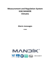
Home screen 5.1
The basic initial screen of the controller after user login is shown in the figure (Fig. 1) with
the following information:
1. Line – system information about the
access level (PIN level), type of AC unit
and, if applicable, the number of the
selected line on the current screen. For
the display integrated in the controller,
in case of an alarm, a bell is displayed at
the end of the first line.
2. Line – current date, time and
temperature according to the configuration (room, supply or exhaust air). The date and time
can be changed by entering the service PIN.
3. Line – ModeSelection allows the user to enter the required regime.
4. Line – The current regime is displayed including the required temperature corresponding to the
regime and temperature period. Additional information is the display of the auxiliary regime
(the “AM” symbol at the beginning of the line) and the switching on of the unit from one of the
controllers without communication (the “•” symbol in front of the current regime). If the
auxiliary regime symbol is displayed, the setting for the current regime may not be observed.
The specific auxiliary regime is then specified on the last line of the home screen under the
AuxilieryMode writing.
The next lines contain menu items for further setting of the AC unit parameters.
The next figures will show the login level required to view them in the top left corner of
the screen.
3│AC Unit Mandík
1
24.07.2022 14:05:24
21.3 °C
ModeSelection
TimeSchedule ►
AM Comfort
22.0 °C
ComponentsMachine
►
TimeSchedule
►
ApplicationInfo
►
LogIn
►
AuxilieryMode
ProtectWaterHeating
Fig. 1

KJM MANDÍK – Detailed operating instructions
M&C KJMPNO 07/2022 MANDÍK, a.s., www.mandik.cz
9
Operating and auxiliary regimes 5.2
The AC unit can operate in four basic operating regimes: Off, Tempering, Economy, and
Comfort. Each of these regimes can be set fixed from the display, from the control panel, from
external switches, or according to a time program.
The auxiliary regime occurs when the unit cannot meet the requirements of the basic
operating regime, for example, when the unit starts up. The auxiliary regime symbol “AM“ is
displayed before the current regime. The specific auxiliary regime is displayed on the last line of
the home screen and the device component screen.
5.2.1 Selecting the operating regime
The ModeSelection line is used to specify the type of operating regime required of the unit.
The current operating regime is displayed on the next line of the display, including the required
temperature. The user can select from the following operating regimes:
TimeSchedule, Off, Tempering, Economy, Comfort
The Economy operating regime usually differs from the Comfort operating regime by
having a lower required temperature, lower fan speed, and lower fresh air quantity. The speeds
for the Comfort and Economy operations are set in the ComponentsMachine
Fans.
Temperatures for the operating regimes are set in ComponentsMachine
TemperatureRegulation. Fresh air quantity is set in ComponentsMachine
Dampers.
5.2.2 Off regime
In this operating regime, the AC unit is turned off. Only safety functions that are designed
to protect certain parts of the unit from damage may operate.
5.2.3 Tempering regime
In this operating regime, the AC unit is off by default and is in one of the following
additional regimes:
Standby – the unit is switched off and only the safety features are operational to protect
some parts of the unit from damage.

KJM MANDÍK – Detailed operating instructions
M&C KJMPNO 07/2022 MANDÍK, a.s., www.mandik.cz
10
FrostProtect – frost protection of the room occurs if the temperature in the room drops
below the required temperature. The unit will start and switch on its heating components. If
the unit includes a mixing damper, 100% air circulation will also be used. The unit will shut off
when the required room temperature is reached. This additional regime is typically used in
the winter when a building is not used for extended periods of time. The start of the
additional regime is indicated on the next line below the selected regime by the FrostProtect
sign and required temperature. The fan speed may correspond to the Comfort or Economy
regime, depending on the last operating regime started. The required temperature is set in
the ComponentsMachine
TemperatureRegulation menu through the FrostProtect (5 °C)
variable.
Freecooling – this regime is typically used in the summer to freely ventilate the building at
night with cooler outside air based on meeting temperature conditions. Starting the additional
regime is indicated on the next line under the selected regime by the Freecooling sign and
required temperature. The fan speeds may correspond to the Comfort or Economy regime,
depending on the last operating regime. The required temperature is set in the
ComponentsMachine
TemperatureRegulation menu via the Freecooling (18 °C) variable.
Ventilation must be enabled in the Configuration menu via the variable Freecooling (Yes). The
other parameters are set in the ComponentsMachine
Freecooling menu and are described
in a separate chapter.
Humidity – this condition occurs when the upper or lower humidity limits are exceeded, and
humidity monitoring is enabled in the ComponentsMachine
HumidityRegulation menu,
while the unit is off, including setting the menu fan speed to a non-zero value.
AirQuality – this condition occurs when the air quality limit is reached and at the same time
air quality monitoring is enabled in the ComponentsMachine
AirQuality menu with the
unit off, including setting the menu fan speed to a non-zero value.
5.2.4 Attenuation regime
In this operating regime, the AC unit is switched on in the so-called Economy regime,
where the required fan speed and the required temperature are lower by default compared to the
Comfort regime. The required speed and temperature are user adjustable for summer and winter
separately. The control controls the individual components (heating, cooling, and humidification)

KJM MANDÍK – Detailed operating instructions
M&C KJMPNO 07/2022 MANDÍK, a.s., www.mandik.cz
11
to achieve the required parameters. This regime of operation is usually used outside dwelling or
working hours.
The fan speeds are set in the ComponentsMachine
Fans menu via the Economy (80%)
variable for the supply and exhaust fans separately. The required temperature is set in the
ComponentsMachine
Temperatures menu via the variable Economy (18 °C).
5.2.5 Comfort regime
In this operating regime, the AC unit is switched on in a regime where the required fan
speed is set to the comfort limit, and the required temperature is set to the comfort value for
summer and winter separately. The control controls the individual components (heating, cooling,
and humidification) to achieve the required parameters. This operating regime is usually used
during dwelling or working hours.
The fan speeds are set in the ComponentsMachine
Fans menu via the Comfort (100%)
variable for the supply and exhaust fans separately. The required temperature is set in the
ComponentsMachine
Temperatures menu via the variable Comfort (22 °C).
5.2.6 Auxiliary regime
Information about the occurrence of an auxiliary regime is displayed with the AM symbol in
front of the current regime. The type of auxiliary regime itself is displayed at the end of the start
screen or at the end of the ComponentsMachine menu. The auxiliary regime occurs when a
situation arises that requires a temporary change in the operation of the AC unit, due to too high
or low temperature, failure of a component, non-standard operation of a component, protection
of the unit, etc. The following auxiliary regimes may occur:
CompenssationSpeed – occurs when the supply temperature drops and compensation is
enabled for any of the options in the ComponentsMachine
Fans menu:
MixingCompensation
CompensationTemperature
CoolError
Defrost
HeatErr

KJM MANDÍK – Detailed operating instructions
M&C KJMPNO 07/2022 MANDÍK, a.s., www.mandik.cz
12
Ventilation – after the unit has been shut down by the user or since a fault, ventilation is
always performed for at least 60 s. Only when a fault occurs from fire sensors or fire dampers,
the unit shuts down immediately. If the unit contains gas or electric heating, venting of the heat
exchangers shall be carried out until the supply air temperature falls 5 °C below the maximum
calculated supply air temperature. However, max. 10 minutes.
Preheat – it signals the preheating of the water heating when the unit is started. The fan speed
can be adjusted according to the settings in the menu ComponentsMachine
WaterHeating
CompenssationSpeed.
Boiler – the operation of the fans is blocked until there are no heating water requirements in
the boiler room.
Start – indicates the start-up status of the components when the unit is started, at which point
the preheat may be activated, adjusting the start position of the dampers, recuperation and fan
speed to ensure that the supply air temperature is optimum and the water heating is protected
in winter. The related parameters in the ComponentsMachine menu are:
TemperatureRegulation
StartDuration
Fans
StartingSpeed
FreshAir
StartFreshAir
WaterHeating
Preheat
SuperiorBlock – operation of the AC unit is blocked from a superior device, usually allowing the
AC unit to turn on based on meeting technological or safety conditions, such as a fire alarm.
Test – signals that the device is on for testing. Testing is described in a separate chapter.

KJM MANDÍK – Detailed operating instructions
M&C KJMPNO 07/2022 MANDÍK, a.s., www.mandik.cz
13
6 Equipment components
The AC unit consists of individual mechanical components that ensure its required function
with the required parameters. Depending on the technical specification, these components are
configured in the measuring and control system and then displayed in item ComponentsMachine.
The components include, for example, Temperatures, TemperatureRegulation, Fans, Burner,
ElectricalHeating, WaterHeating, CondensingUnit, Recuperator, Dampers, Filters, and others.
Every component displays its current performance or status. Selecting a component displays more
detailed information. Basic component information is available without logging in. These include
the following items:
State (Off/……..) - informs about the status and required regime of operation. The specific
states may vary from component to component and are therefore described in detail for each
component.
Power (%) – informs about the required output of the device.
OperatingHour – may be used as information for service personnel due to wear and tear on
the fan or other components.
NumberStarts – indicates how the unit is operated. A big number of starts may indicate
improper operation of the entire AC unit.
The following describes parameters that apply to most components and have the same
function, so they do not need to be described for every component separately. These parameters
can only be accessed after a service login:
PID–Regulation (BLOCK/OG/UG/REG/Y–NV/UDEF) – contains the control parameters that
determine the quality and speed of the required output control based on the required and
actual values. The values are set by default at the factory and should only be changed by a
person knowledgeable in control systems. The standard factory set values are shown for every
component. The meaning of the individual control states is as follows:
BLOCK – controller function is not released,
OG – forced maximum output, parameter O,
UG – forced minimum output, parameter O,
REG – controller is active,
Y–NV – invalid setpoint, parameter S,
UDEF – invalid output value, parameter O.

KJM MANDÍK – Detailed operating instructions
M&C KJMPNO 07/2022 MANDÍK, a.s., www.mandik.cz
14
The meaning of the individual control parameters is:
S (% or °C) – setpoint.
P (% or °C) – current value.
O (% or °C) – PID controller output.
TI (s) – integration component.
KP – proportional constant.
TD (s) – derivative component.
PID–Regulation values are only available for some components.
OrderHeat, OrderCool (--/1/2/3/…) – this parameter determines the order of the component
in the heating or cooling sequence. Selection -- means that the component will not be
included in the sequence. The order used depends on the number of components in every
sequence. For example, in the case of three heating components in the order of mixing,
recuperation and water heating, the order is set to mixing 1, recuperation 2, and water
heating 3. In the case of two cooling components in the order of heat recovery and
condensing unit, the heat recovery is set to order 1 and condensing unit to 2. The components
may not have the same order in the same sequence.
Control (0–10V/2–10V/10–0V/10–2V) – this parameter determines the range of the output
control signal for the actuator typically controlling the valve or damper. This value is selected
according to the type of actuator used.
0–10V – Output signal 0% = 0V, 100% = 10V.
2–10V – Output signal 0% = 2V, 100% = 10V.
10–0V – Output signal 0% = 10V, 100% = 0V.
10–2V – Output signal 0% = 10V, 100% = 2V.
0–5V – Output signal 0% = 0V, 100% = 5V. It applies for glycol only.
TimeOpen (90s) – time for the actuator to move from one extreme position to the other.
When monitoring the actuator position feedback signal, the difference between the predicted
and actual position may indicate a malfunction of a device mechanically connected to the
actuator (damper, valve, etc.). If the actuator position feedback signal is not monitored, this
value of the assumed damper position is only informative.
Nonsensitive (20%) – this parameter is only meaningful when monitoring the damper position
feedback signal. If the difference between the predicted and actual damper position is greater

KJM MANDÍK – Detailed operating instructions
M&C KJMPNO 07/2022 MANDÍK, a.s., www.mandik.cz
15
than the non-sensitivity, then a damper failure may be indicated and consequently the
component with that damper or the entire AC unit may shut down.
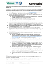
Temperatures 6.1
This menu contains information about the measured temperatures according to the
settings in the configuration. The location of the temperature sensors in the air handling unit and
air ducts can be seen in Figure 2.
Legend:
T1 – Outdoor (ODA) T4 – Preheat – after 1st heating T7 – Room
T2 – Inlet T5 – Reheat – before 2nd heating T8 – Extract (ETA)
T3 – Supply Recuperation T6 – Supply (SUP) T9 – Extract Recuperation
T10 – Exhaust (EHA)
Fig. 2 - Temperature sensor locations
Following are the descriptions of every temperature sensor, including installation methods
and other related settings:
Room – if configured, the sensor should be placed in the room that is the target of the air
conditioning so that the measured temperature is not affected by any local influences, such
as radiators, sunlight through a window, etc. If not configured, it can be replaced by a supply

KJM MANDÍK – Detailed operating instructions
M&C KJMPNO 07/2022 MANDÍK, a.s., www.mandik.cz
16
or exhaust air temperature sensor. Multiple room sensors can be installed and the resulting
room temperature is determined by the MoreRoomSensors parameter.
RoomUnit – temperature of the sensor located in the room unit. The room unit must be
configured to display this temperature.
Preheat – this sensor is used when the supply air is required to be preheated and is placed
between preheating and reheating or cooling.
Supply – in most cases, at least this sensor is configured to measure the supply air
temperature. The temperature sensor is placed after the last heating or cooling component
before the air enters the room. The maximum duct temperature is set at 50 °C per health and
fire regulations.
Flue – this sensor must be configured if the unit contains a gas heater as it ensures the proper
operation and protection of the gas exchanger, including the emergency function. It is also
used to control the gas exchanger bypass damper to mitigate condensation and heat the
exchanger faster when the gas heater starts. The temperature sensor is placed in a sump
welded above the flue way base. The QAZ21.5120 sensor from Siemens with the NI1000
measuring element is supplied as standard.
Outdoor – should also be configured for all the air conditioning units to ensure correct
operation of the control system especially when the unit is started up or shut down. The
sensor should be located outdoors so that it is protected from weather influences that would
improperly affect the M&C. For example, direct sunlight, rain, frost, wind, etc. The outdoor
sensor is also used to control air circulation with a mixing damper or to efficiently use the
recuperator. This sensor should always be configured as it is often tied to protection and
start-up functions.
HeatingWaterDrain – if the unit contains a water heater, then a temperature sensor must be
configured to measure the heating water temperature. The heating water drain temperature
sensor ensures proper operation and protection of the water heat exchanger. It is placed on
the water exchanger discharge piping, called the return piping, so that it measures the actual
temperature of the discharged water.
HeatingWaterSupplied – this sensor is placed on the heating water supply line to measure
the actual temperature of the water supplied to the water exchanger. It can be used to signal
a heating water requirement to the boiler room.

KJM MANDÍK – Detailed operating instructions
M&C KJMPNO 07/2022 MANDÍK, a.s., www.mandik.cz
17
CoolingWaterDrain – this sensor can be configured if the unit contains a water cooler. It is
placed on the water exchanger discharge piping, called the return piping, so that it measures
the actual temperature of the cooling water. The sensor is for informational purposes only.
CoolingWaterSupplied – this sensor is placed on the cooling water supply line to measure
the actual temperature of the water supplied to the water exchanger. The sensor is for
informational purposes only.
Recuperation
Inlet – placed upstream of the recuperator on the air inlet.
Supply – located after the recuperator on the air supply. Together with the inlet sensor, it
provides information on the current thermal performance of the recuperation
Extract – ensures the correct defrost protection function of the recuperator. The
temperature sensor is placed behind the recuperator on the air outlet.
Extract – temperature sensor is in many cases configured as a replacement for the room
temperature sensor, as it senses the temperature of the exhaust air from the room without
being affected by local room influences. It is placed in the exhaust duct.
Exhaust – used to measure the temperature of the exhaust air. It is placed at the end of the
exhaust duct.
MoreRoomSensors (Average/OG/UG/1/2/SummerMin/WinterMin) – with multiple room
temperature sensors, determines how the final room temperature is calculated or assigned.
When 1, 2 is selected, the final room temperature is given only by the selected sensor, and
the other sensors are only informative. For other selections, the final value is calculated as a
mathematical average, maximum or minimum. The SummerMin option selects the lowest
measured room temperature in the summer and the highest in the winter. The WinterMin
option selects the lowest measured room temperature in the winter and the highest in the
summer.
Display (Room/Extract/Supply/Preheat/Exhaust) – selects the temperature sensor whose
value will be displayed on the second line of the Home screen next to the current time. By
default, a reference temperature sensor is selected and compared to the required
temperature. A room, supply or exhaust air temperature sensor can be selected.

KJM MANDÍK – Detailed operating instructions
M&C KJMPNO 07/2022 MANDÍK, a.s., www.mandik.cz
18
Temperature control 6.2
Temperature control can be direct or cascading and depends on the selection of the
required temperature in the Configuration menu. In the case of the required supply temperature
or preheat temperature, it is direct control. For the other options, it is cascade control (PID–
Supply), which allows better control of the required temperature. Temperature control includes
other parameters that affect the operation of the AC unit. Temperature control is accessible only
after service login.
State (Off/Ventilate/Heat/Cool) – current state of temperature control.
Currently (°C) – current temperature on the setpoint sensor.
DesiredSupply (22 °C) – current required supply air temperature.
Required (°C) – required temperature for all regimes if the unit is controlled from a room unit.
Summer – required temperatures for every regime in the summer, if the unit is not controlled
from its room unit:
Comfort (22 °C) – required temperature for the Comfort regime in the summer.
Economy (18 °C) – required temperature for the Economy regime in the summer.
Winter – required temperatures for every regime in the winter if the unit is not controlled
from its room unit:
Comfort (23 °C) – required temperature for the Comfort regime in the winter.
Economy (19 °C) – required temperature for the Economy regime in the winter.
FrostProtect (5 °C) – required heating temperature in the Tempering regime.
Freecooling (18 °C) – required ventilation temperature in the Tempering regime.
Compensation (0 °C) – difference between the outdoor temperature and the setpoint
temperature at which the setpoint compensation is activated in the Economy or Comfort
regime. Setpoint compensation is used at higher outdoor temperatures and consists of
shifting the setpoint temperature, depending on the outdoor temperature. At the value of
0°C, the compensation is blocked.
Example for Compensation = 6 °C in the Comfort regime:
Outdoor temperature ≤ 28 °C
required temperature = 22 °C.
Outdoor temperature = 32 °C
required temperature = 26 °C.
DesiredPreheat (0 °C) – required temperature for water or electric heating preparing air for
another component, usually a condensation unit. For proper operation, the temperature

KJM MANDÍK – Detailed operating instructions
M&C KJMPNO 07/2022 MANDÍK, a.s., www.mandik.cz
19
sensor for preheat must be configured and the preheat must not have a valid order set,
OrderHeat =---.
PID–Supply – is a cascade control that calculates the required supply temperature based on
the required and actual room temperature or discharge temperature. The factory default
values are: TI = 900 s, KP = 10, WPD = 0 °C. The only apply when
configuration RequiredTemperature features no selected Supply and Preheat temperatures.
If the RequiredTemperature configuration features the Supply or Preheat temperature, then
this PID control is not applied, and the required temperature is equal to the required supply
air temperature. The calculated required temperature of the air supplied by the PID is
between HighLimitSupply and LowLimitSupply.
HighLimitSupply (30 °C) – current upper limit of the required supply air temperature, which is
determined by the Fixed or Shift upper limit values.
Fixed (30 °C) – maximum required static supply air temperature. This value applies as the
current maximum HighLimitSupply limit only if the upper limit is subject to Shift = 0 °C.
Shift (0 °C) – non-zero value defines the current maximum required supply air temperature
limit HighLimitSupply as the sum of the required temperature by regime (Comfort,
Economy, Tempering,) and Shift. The maximum required supply air temperature will
change dynamically as the required temperature changes.
LowLimitSupply (16 °C) – current minimum required supply air temperature limit, which is
determined by the Fixed or Shift low limit values.
Fixed (16 °C) – maximum required static required supply air temperature. This value
applies as the current LowLimitSupply minimum limit only if Shift = 0 °C.
Shift (0 °C) – non-zero value defines the current minimum limit of the required supply air
temperature LowLimitSupply as the difference between the required temperature per the
regime (Comfort, Economy, Tempering, and Shift). The minimum required supply air
temperature will change dynamically as the required temperature changes.
CascadeNonSensitive (6 °C) – determines when to shut down the heating or cooling
components of the unit when the minimum or maximum supply air temperature limit is
exceeded:
If the supply air temperature exceeds the HighLimitSupply + CascadeNonSensitive value,
then all the heating components of the unit will immediately shut down or cooling
components of the unit will turn on.

KJM MANDÍK – Detailed operating instructions
M&C KJMPNO 07/2022 MANDÍK, a.s., www.mandik.cz
20
If the supply air temperature drops below the LowLimitSupply – CascadeNonSensitive
value, then all the cooling components of the unit will immediately shut down, or the
heating components of the unit will turn on.
ShiftHC (2 °C) – shifts the required supply air temperature calculated by the cascade PID
control for the Heat and Cool to achieve energy savings:
Heat state – supply air temperature setpoint range is between HighLimitSupply – (ShiftHC
/ 2) and LowLimitSupply – (ShiftHC / 2).
Cool state – supply air temperature range is between HighLimitSupply + (ShiftHC / 2) and
LowLimitSupply + (ShiftHC / 2).
HighSplyOff (No/Recuperation/Heating) – determines how much of the heating section will
shut off when the upper limit of supply temperature plus insensitivity is exceeded. This
feature is particularly applicable to condensing units with non-standard controls where the
recuperation unit shuts down instead of the condensing unit. This will reduce the frequency of
condensing unit shutdowns.
ClimaTemp (Outdoor/Room/Supply/Extract/Preheat/Exhaust/Room1/
Room2/Season/Contact) – selects a temperature sensor or other condition for the controller
to decide whether to heat or cool the unit.
When either temperature is selected, the required temperature is compared to the
selected temperature.
Season – the controller heats or cools based on the parameters set in item
TemperatureSeason. In the Summer temperature season, the unit only cools and in the
Winter, it only heats.
Contact – the climate temperature is replaced by an external contact switching the
heating or cooling regimes from the superior system (AssignmentInputs/Outputs
ExternalSwitches
Cool/Heat). By default, the unit is switched to cooling regime when
the contact is open and to heating regime when the contact is open.
ClimaShift (0 °C) – only has meaning if either temperature is selected as ClimaTemp. For
example, with the selected outdoor climate temperature, a required room temperature of 23
°C and a climate shift of 2 °C, climate insensitivity of 0 °C will result in an outdoor limit
temperature for switching between heating and cooling of 25 °C.
ClimaNonSensitive (1 °C) – only has meaning if either temperature is selected as ClimaTemp.
It is used to specify the limit temperature at which the unit should heat and at which it should
/