Moxa NPort Express Series User manual
- Category
- Networking
- Type
- User manual

NPort DE-311
Hardware Installation Guide
Fifth Edition, August 2014
www.moxa.com/product
© 2014 Moxa Inc. All rights reserved.

NPort DE-311
Hardware Installation Guide
The software described in this manual is furnished under a license agreement and may be used only in accordance with
the terms of that agreement.
Copyright Notice
© 2014 Moxa Inc. All rights reserved.
Trademarks
The MOXA logo is a registered trademark of Moxa Inc.
All other trademarks or registered marks in this manual belong to their respective manufacturers.
Disclaimer
Information in this document is subject to change without notice and does not represent a commitment on the part of
Moxa.
Moxa provides this document as is, without warranty of any kind, either expressed or implied, including, but not limited
to, its particular purpose. Moxa reserves the right to make improvements and/or changes to this manual, or to the
products and/or the programs described in this manual, at any time.
Information provided in this manual is intended to be accurate and reliable. However, Moxa assumes no responsibility for
its use, or for any infringements on the rights of third parties that may result from its use.
This product might include unintentional technical or typographical errors. Changes are periodically made to the
information herein to correct such errors, and these changes are incorporated into new editions of the publication.
Technical Support Contact Information
www.moxa.com/support
Moxa Americas
Toll
-free: 1-888-669-2872
Tel:
+1-714-528-6777
Fax:
+1-714-528-6778
Moxa China (Shanghai office)
Toll
-free: 800-820-5036
Tel:
+86-21-5258-9955
Fax:
+86-21-5258-5505
Moxa Europe
Tel:
+49-89-3 70 03 99-0
Fax: +49-89-3 70 03 99-99
Moxa Asia
-Pacific
Tel:
+886-2-8919-1230
Fax: +886-2-8919-1231
Moxa India
Tel:
+91-80-4172-9088
Fax:
+91-80-4132-1045

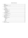
Table of Contents
1. Introduction ...................................................................................................................................... 1-1
Features ............................................................................................................................................ 1-2
Product Specifications ......................................................................................................................... 1-2
Package Checklist ............................................................................................................................... 1-3
Front/Top/Rear/Bottom Panel Views ...................................................................................................... 1-4
2. Overview ........................................................................................................................................... 2-1
LED Indicators .................................................................................................................................... 2-2
Housing ............................................................................................................................................. 2-2
DIN Rail ..................................................................................................................................... 2-2
Wall Mount ................................................................................................................................. 2-3
3. Serial Installation ............................................................................................................................. 3-1
DIP Switch Settings ............................................................................................................................ 3-2
DB9 Female Connector Pinouts ............................................................................................................. 3-2
RS-232 Pinouts ........................................................................................................................... 3-2
RS-232 Loopback Tester .............................................................................................................. 3-3
RS-422/485 Pinouts..................................................................................................................... 3-3
RS-422 Loopback Tester .............................................................................................................. 3-3
Mini Adapter ............................................................................................................................... 3-4
4. Ethernet Installation ......................................................................................................................... 4-1
Connecting to the Ethernet Port ............................................................................................................ 4-2
Connecting to a Hub or Switch ...................................................................................................... 4-2
Connecting to a PC ...................................................................................................................... 4-2
5. Power Connection ............................................................................................................................. 5-1
Connecting the Power Adapter .............................................................................................................. 5-2
Power Status Check ............................................................................................................................ 5-2
A. Telnet Console................................................................................................................................... A-1
Opening the Telnet Console ................................................................................................................. A-2
Navigating the Telnet Console .............................................................................................................. A-2
Main Menu .................................................................................................................................. A-3
serverConfig ............................................................................................................................... A-3
Serialport ................................................................................................................................... A-4
Monitor ...................................................................................................................................... A-4
Ping ........................................................................................................................................... A-4
Restart ....................................................................................................................................... A-4
Exit ........................................................................................................................................... A-5
Menu Tree ......................................................................................................................................... A-5
B. Serial Console ................................................................................................................................... B-1
C. Declaration of Conformity ................................................................................................................. C-1

1
1. Introduction
Welcome to Moxa’s NPort Express, a compact palm-sized communications device that allows you to control
RS-232/422/485 serial devices over a TCP/IP Ethernet.
The following topics are covered in this chapter:
Features
Product Specifications
Package Checklist
Front/Top/Rear/Bottom Panel Views

DE-311 Introduction
1-2
The NPort Express DE-311 provides a data communications solution for connecting Windows and Linux hosts to
asynchronous serial devices over a TCP/IP Ethernet network. Using the NPort Express is like adding a serial port
to your PC using a serial board, but with the added advantage of the TCP/IP network. With the NPort Express,
Windows hosts can connect to a native serial port and PC-based Linux hosts can connect to a real tty port, all
over a network. Virtually any serial device can be attached to the NPort Express to become network accessible,
and the network can be configured to allow control of the device from any location in the world.
After driver installation, Windows will recognize the serial port on the NPort Express as a real COM port; Linux
will recognize the port as a real tty port. The NPort Express provides basic transmit/receive data functions, as
well as RTS, CTS, DTR, DSR, and DCD control signals.
The NPort Express can be used with your existing applications and comes with a software utility and
maintenance wizard.
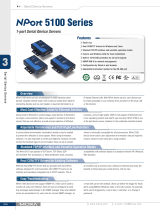
Features
• 3-in-1 RS-232/422/485 serial interface
• Auto-detecting 10/100 Mbps Ethernet connection
• Built-in Ethernet and TCP/IP protocol
• Compact size for easy integration
• Supports MAC based IP configuration
• Supports configuration store and copy for easy deployment
• Supports Windows Real COM drivers and Linux real TTY drivers
• Operation modes include TCP Server, TCP Client, UDP Server/Client, Ethernet Modem, and Pair Connection
Product Specifications
Hardware
Processor 16 bit CPU
Memory 512 KB
Connector DB9 female
Interface
LAN Auto-detecting 100BaseTX (10/100 Mbps)
Serial RS-232/422/485 (DIP switch selectable)
No. of serial ports 1
Signals RS-232: TxD, RxD, RTS, CTS, DTR, DSR, DCD, GND
RS-422: TxD+/-, RxD+/-, RTS+/-, CTS+/-, GND
RS-485: Data+/-, GND
Performance
Speed Rev 2.1: 50 bps to 230.4 Kbps
Rev 2.2: 150 bps to 230.4 Kbps
Configuration
DE-311 Parity None, Even, Odd
Data Bits 7, 8
Stop Bits 1, 2 (with parity setting of None)
DE-311 Rev. 2 Parity None, Even, Odd, Space, Mark
Data Bits 5, 6, 7, 8
Stop Bits 1, 1.5, 2
Supported OS
Windows XP, Windows 2000, Windows NT, Windows 95/98/Me Real COM driver, Unix fixed tty driver for
UnixWare SVR4.2, UnixWare 7 SVR5, SCO Open Server, SCO Unix, Linux real tty driver

DE-311 Introduction
1-3
Protocols
TCP, IP, UDP, Telnet, RTelnet, DHCP, ICMP, BootP
Operation Modes
Driver Mode, TCP Server, TCP Client, UDP Server/Client, Ethernet Modem, Pair Connection
Management
Serial console Telnet console NPort Configurator for Windows/Linux Real COM Installer for Windows Monitor
Utility for Windows Firmware upgrade function supported NPort Admin for Linux tty driver
Supported OS
Windows XP, Windows 2000, Windows NT, Windows 95/98/Me Real COM driver, Unix fixed tty driver for
UnixWare SVR4.2, UnixWare 7 SVR5, SCO Open Server, SCO Unix, Linux real tty driver
Power and Environment
Power Requirements DE-311 DC 9V to 20V, 400 mA (max.) at 9V
DE-311 Rev. 2 DC 9V to 30V, 300 mA (max.) at 9V
Operating Temperature 0 to 55°C
Operating Humidity 5 to 95% RH
Dimensions (W×D×H) 90 × 100.4 × 22 mm (including ears)
67 × 100.4 × 22 mm (without ears)
Regulatory Approvals FCC, CE, UL, CUL, TÜV
Package Checklist
DE-311/110V: 1 NPort Express DE-311 Universal Serial Device Server
DE-311/230V: 1 NPort Express DE-311 Universal Serial Device Server
Both models include
• Windows 95/98/ME/NT/2000/XP Real COM driver, Linux real tty driver
• NPort Management Suite software
• User’s Manual, software CD-ROM
• DB9/M – DB9/M adapter
Optional Accessories
DIN rail mounting kit: For 35 mm DIN rail; includes 4 screws

DE-311 Introduction
1-4
Front/Top/Rear/Bottom Panel Views
1. DB9 female serial port
2. DIP switches
3. DIN rail screw holes
4. Wall mount screw holes
5. RJ45 10/100BaseTX Ethernet port
6. Reset button—hold down for
• 3 sec to erase password
After 3 sec, the ready LED will flash every twice
every second. Release the reset button at this time
to erase password.
• 10 sec to load factory defaults
After 10 sec, the ready LED will flash five times each
second. Release the reset button at this time to load
factory defaults
7. Power input
8. Rubber base pads
9. Technical information


DE-311 Overview
2-2
LED Indicators
The NPort Express’s top panel contains five LED indicators, as described in the following table.
LED Name LED Color LED Function
PWR
red Power is on
off Power is off, or power error condition exists
Link
orange 10 Mbps Ethernet connection
green 100 Mbps Ethernet connection
off Ethernet cable is disconnected, or has a short
Ready
green The NPort Server is ready
blinking
The NPort
is requesting an IP address from the DHCP or BootP server. After
receiving the IP, the LED will stop blinking.
Note: The LED will also blink while holding down the reset button; see page
1-5 for details.
off The NPort Server has malfunctioned
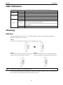
Housing
DIN Rail
The DIN rail attachments provide a very convenient installation option for many industrial applications.
Installation instructions are as follows:
STEP 1:
Use the screws to attach the DIN rail mounts to the NPort Express
’s ears.
STEP 2:
The
two ends of the rail mount are named A and B.
Hook the A end over the top edge of the rail.
STEP 3:
Push the unit against the rail. You should hear the B
end clicking into place over the bottom edge of the rail.
NOTE
The DIN rail
-mounting kit is an optional accessory.
To remove the NPort Express from the DIN rail, simply reverse Steps 2 and 3 above. Use your fingers to pull
down on the B end, which should release the bracket from the rail.

DE-311 Overview
2-3
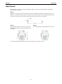
Wall Mount
Wall installation is another convenient installation option for many industrial applications. Installation
instructions are as follows:
STEP 1:
Obtain two screws with heads no greater than 6.5 mm in diameter and shafts no greater than 3 mm in
diameter. At
the desired wall location, drive the screws into the wall with 7.8 cm separation between the
screws. Do not drive the screws all the way into the wall; leave about 2 mm clearance.
STEP 2:
Hang the NPort Express on the two screws using
the apertures
on the ears, and then slide the unit
downwards.
STEP 3:
For added stability, simply tighten the two screws.
To remove the NPort Express from the wall mount, simply reverse Steps 2 and 3.


DE-311 Serial Installation
3-2
DIP Switch Settings
The top panel contains a table which describes how to configure the serial port using the three DIP switches.
SW1 Serial Connection SW2 SW3 Serial Interface Mode
ON Console (19200,N,8,1) --- --- RS-232
OFF Data Comm.
OFF OFF RS-232
OFF ON RS-422
ON OFF RS-485 by RTS
ON ON RS-485 ADDC
The DIP switches are located on the rear panel. SW1 toggles the serial port between data and console operation
(ON or up for serial console operation, and OFF or down for data communication). Data operation is the normal
operating mode for controlling serial devices; console operation is for accessing the NPort Express
configuration parameters. Note that after modifying SW1 settings, the NPort Express will reboot to initialize the
new mode. You must wait a few seconds for the green Ready LED to blink off and then on again, indicating that
the function of the serial port has been changed.
SW2 and SW3 control the serial port’s data communication interface. Note that RTS stands for Ready to Send
and ADDC stands for Automatic Data Direction Control.
Keep the following points in mind when setting the DIP switches.
• RS-232 Console
To use the serial port as a console connection, such as when using Moxa PComm Terminal Emulator or
HyperTerminal, set SW1 to the ON position.
• Telnet Connection
Some configuration may be carried out through a Telnet connection, during which data is transmitted
through the NPort Express’s Ethernet port. However, you must set SW1 to the OFF position to establish a
Telnet connection.
DB9 Female Connector Pinouts
RS-232 Pinouts
DB9 (Female) PIN RS-232
1 DCD
2 TxD
3 RxD
4 DSR
5 GND
6
DTR
7 CTS
8 RTS
9 ---

DE-311 Serial Installation
3-3
RS-232 Loopback Tester
PIN Signal
1 DCD
2 TxD
3
RxD
4 DSR
5 GND
6 DTR
7 CTS
8 RTS
RS-422/485 Pinouts
DB9 (Female) PIN RS-422 RS-485
1 RxD-(A) ---
2 RxD+(B) ---
3 TxD+(B) Data+(B)
4 TxD-(A) Data-(A)
5 GND GND
6 CTS-(A) ---
7 CTS+(B) ---
8 RTS+(B) ---
9 RTS-(A) ---
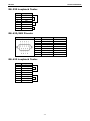
RS-422 Loopback Tester
PIN
Signal
1 RxD-(A)
2 RxD+(B)
3 TxD+(B)
4 TxD-(A)
5 GND
6 CTS-(A)
7 CTS+(B)
8 RTS+(B)
9 RTS-(A)

DE-311 Serial Installation
3-4
Mini Adapter
The NPort
Express DE-
311 accepts devices with both male and female connectors. A
D
-shell female serial connector is built-in, and a DB9 male null-modem adapter is
included as a standard accessory.
If you want to make your own DB9 male to DB9 male null-modem (or crossover) cable, the correct pinouts are
as follows:
PIN RS-232 RS-422 RS-485
1 DCD RxD-(A) ---
2 TxD RxD+(B) ---
3 RxD TxD+(B) Data+(B)
4 DSR TxD-(A) Data-(A)
5 GND GND GND
6 DTR CTS-(A) ---
7
CTS
CTS+(B)
---
8 RTS RTS+(B) ---
9 --- RTS-(A) ---
NOTE
The adapter is included with the DE
-311 as a standard accessory.


DE-311 Ethernet Installation
4-2
Connecting to the Ethernet Port
Connecting to a Hub or Switch
For most applications, plug one end of your Ethernet cable into the NPort Express’s 10/100BaseTX port, and the
other end into a hub or switch that is connected to your network. In this case, you should use a standard
straight-through Ethernet cable, which is readily available from many commercial vendors. You may also make
your own cable by referring to the following cable wiring diagram.
Connecting to a PC
If you are connecting the NPort Express directly to your PC’s Ethernet port, use a crossover Ethernet cable. You
can make your own crossover cable by referring to the following cable wiring diagram.


DE-311 Power Connection
5-2
Connecting the Power Adapter
The following steps explain how to connect the NPort Express’s power adapter:
1. Plug the power adapter’s DC plug into the DC-IN jack on the NPort Express.
2. Plug the power adapter into an electrical outlet.
Note that there is no on/off switch. The NPort Express will turn on automatically as soon as power is supplied.
The red PWR LED will glow to indicate that the unit is receiving power.
Power Status Check
Use the PWR LED to verify that the unit is receiving power. A red light indicates that power is being received.
If the LED is off, no power is being received. If the unit is plugged in and the PWR LED does not light up, there
may be a problem with the unit.

A
A. Telnet Console
The Telnet console is used to view and modify the unit’s configuration. After installing the unit into a serial
device, administrators configure their device remotely by opening a Telnet console session over the network.
The following examples refer to a Telnet console session on a Windows 98 host, but the same instructions
should apply to all Windows operating systems.
The following topics are covered in this appendix:
Opening the Telnet Console
Navigating the Telnet Console
Main Menu
serverConfig
Serialport
Monitor
Ping
Restart
Exit
Menu Tree

DE-311 Telnet Console
A-2
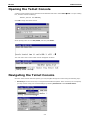
Opening the Telnet Console
A Telnet console session may be opened from the Windows Start menu. Select Start
Run... to open a dialog
box, and then enter the following:
telnet [unit’s IP address]
Click OK to begin the Telnet session.
At the prompt, enter “1” for ansi/vt100, and then press Enter.
The main menu of the unit’s Telnet console will appear as shown.
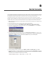
Navigating the Telnet Console
Once the Telnet console has been opened, you may navigate through the console using the following keys:
• Arrow keys: Use the arrow keys to navigate between different options. If the arrow keys do not respond,
you may need to verify your terminal settings by selecting Preferences in the Terminal menu:
Page is loading ...
Page is loading ...
Page is loading ...
Page is loading ...
Page is loading ...
-
 1
1
-
 2
2
-
 3
3
-
 4
4
-
 5
5
-
 6
6
-
 7
7
-
 8
8
-
 9
9
-
 10
10
-
 11
11
-
 12
12
-
 13
13
-
 14
14
-
 15
15
-
 16
16
-
 17
17
-
 18
18
-
 19
19
-
 20
20
-
 21
21
-
 22
22
-
 23
23
-
 24
24
-
 25
25


Moxa NPort Express Series User manual
- Category
- Networking
- Type
- User manual
Ask a question and I''ll find the answer in the document
Finding information in a document is now easier with AI
Related papers
-
Moxa NPort Express Series Quick setup guide
-
-
-
-
 Moxa Technologies NPort Express DE-211 Quick Install Guide
-
Moxa NPort IA5000 Series Quick setup guide
-
-
-
Moxa NPort 5000AI-M12 Series User manual
-
Moxa NPort 5600-DTL Series User manual

Other documents
-
CableWholesale 31D1-07200 Datasheet
-
Stinger SPTG1 User manual
-
 Moxa Technologies Server DE-308 User manual
-
 Moxa Technologies DE-332 User manual
-
 Moxa Technologies NPort Express DE-211 User manual
-
 Moxa Technologies DE-304 User manual
-
B&B Electronics U-linx USR602 Quick start guide
-
 Moxa Technologies 5100 User manual
-
DeLOCK 65255 Datasheet
-
 Moxa Technologies 5600 User manual


