>25’’ ①
②
③
beep
<1’’ ④
⑤
A/01
A/01
A/01
A/01
F
❶
❷
❸
❹
❺
Page 8 - Manual FA01533-EN - 10/2021 - © CAME S.p.A. - The contents of this manual may be changed, at any time, and without notice. - Translation of the original instructions
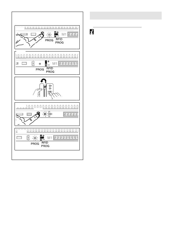
PROGRAMMING
Of an intercom group F
Programming the intercom group
must be done after assigning the type
of call key or call code to all the internal
receivers.
Press the power supply’s PROG key for
at least 25 seconds, until the PROG LED
flashes quickly ❶ and then put the RFID
jumper in position “+” ❷.
To enable the intercom function, swipe
on the internal receiver that you want to
programme, and press the call button you
want to call from: a beep will sound to show
that programming has taken place ❸.
Continue by repeating the same operations
for all the other internal receivers to be
included in the intercom group.
To leave programming, briefly press the
power supply’s PROG key
❹
and put the
RFID PROG jumper in the default position ❺.
☞ If no action is performed, the procedure will automatically end after 30 minutes.
Once an internal receiver has been included in an intercom group by assigning the call
key, it can no longer be excluded from that group.
To change the call key of an internal receiver that has already been programmed to have
the intercom facility, and therefore add new internal receivers to the group, just repeat
the sequence of operations described above.


