Page is loading ...

SA Electric Shoe Brakes
Magnetek SA Electric Shoe Brakes
Instruction Manual
Part Number: 452040 R0
May 2019
©Copyright 2019 Magnetek Material Handling

SA Electric Shoe Brakes Instruction Manual
May 2019
Page 2 of 44
Page Intentionally Left Blank

SA Electric Shoe Brakes Instruction Manual
May 2019
Page 3 of 44
Table of Contents
1 General Description............................................................................................................................ 7
2 Application ..........................................................................................................................................9
3 Description of Operation..................................................................................................................10
3.1 Torque Springs...........................................................................................................................12
3.2 Air Gap Indicator ........................................................................................................................14
3.3 Pushrods ....................................................................................................................................16
3.4 Shoe Equalization Bolts ............................................................................................................. 17
3.5 Hand Release Mechanism .........................................................................................................18
3.6 Limit Switches ............................................................................................................................ 18
3.7 Other .......................................................................................................................................... 19
4 Adjustment ........................................................................................................................................ 20
4.1 Manual Operation.......................................................................................................................20
4.2 Pushrod ......................................................................................................................................21
4.3 Torque Spring Bolts....................................................................................................................22
4.4 Shoe Equalization Bolts ............................................................................................................. 23
4.5 Anti-drag Feature ....................................................................................................................... 23
4.6 Hand-Release Mechanism .........................................................................................................24
4.7 Limit Switches ............................................................................................................................ 25
5 Electrical Detail ................................................................................................................................. 26
6 Installation.........................................................................................................................................30
7 Burnishing.........................................................................................................................................35
8 Operational Test ............................................................................................................................... 37
9 Maintenance and Repair .................................................................................................................. 38
9.1 Replacing the Brake Shoes........................................................................................................39
9.2 Coil Assembly.............................................................................................................................40
9.3 Pushrods ....................................................................................................................................41
9.4 Other .......................................................................................................................................... 41
9.5 Inspection ...................................................................................................................................42
9.6 Lubrication..................................................................................................................................42
10 Replacement Parts ........................................................................................................................... 43
11 Long-Term Storage...........................................................................................................................44

SA Electric Shoe Brakes Instruction Manual
May 2019
Page 4 of 44
SERVICE INFORMATION
Your New Electric Shoe Brakes
Thank you for your purchase of Magnetek’s SA Electric Shoe Brakes. Magnetek has set a whole new
standard in performance, dependability, and value with this unique new line of electric shoe brakes.
If your product ever needs modification or service, please contact one of our representatives at the
following locations:
U.S. Service Information
For questions regarding service or technical information contact:
1-866-MAG-SERV
(1-866-624-7378)
International Service
262-783-3500
World Headquarters:
Magnetek, Material Handling
N49 W13650 Campbell Drive
Menomonee Falls, WI 53051
Telephone: 800-288-8178
Website: www.magnetek.com
E-mail: mhcustomerse[email protected]
Fax Numbers:
Main: 800-298-3503
Sales: 262-783-3510
Service: 262-783-3508
© 2019 MAGNETEK
All rights reserved. This notice applies to all copyrighted materials included with this product, including, but
not limited to, this manual and software embodied within the product. This manual is intended for the sole
use of the person(s) to whom it was provided, and any unauthorized distribution of the manual or dispersal
of its contents is strictly forbidden. This manual may not be reproduced in whole or in part by any means
whatsoever without the expressed written permission of MAGNETEK.
Canada Service Information:
161 Orenda Road
Unit 1
Brampton, Ontario
L6W 1W3 Canada
Phone: 800-792-7253
Fax: 905-828-5707
416-424-7617 (24/7 Service pager)
EU Market Contact:
Brian Preston
Magnetek (UK) Ltd.
Unit 3 Bedford Business Centre
Mile Road
Bedford, MK42 9TW UK
Phone: +44-1234-349191

SA Electric Shoe Brakes Instruction Manual
May 2019
Page 5 of 44
PREFACE AND SAFETY
Magnetek, Inc. (Magnetek) offers a broad range of radio remote control products, control products and
adjustable frequency drives, and industrial braking systems for overhead material handling applications.
This manual has been prepared by Magnetek to provide information and recommendations for the
installation, use, operation and service of Magnetek’s material handling products and systems (Magnetek
Products). Anyone who uses, operates, maintains, services, installs or owns Magnetek Products should
know, understand and follow the instructions and safety recommendations in this manual for Magnetek
Products.
The recommendations in this manual do not take precedence over any of the following requirements
relating to cranes, hoists and lifting devices:
• Instructions, manuals, and safety warnings of the manufacturers of the equipment where the radio
system is used,
• Plant safety rules and procedures of the employers and the owners of facilities where the
Magnetek Products are being used,
• Regulations issued by the Occupational Health and Safety Administration (OSHA),
• Applicable local, state or federal codes, ordinances, standards and requirements, or
• Safety standards and practices for the overhead material handling industry.
This manual does not include or address the specific instructions and safety warnings of these
manufacturers or any of the other requirements listed above. It is the responsibility of the owners, users
and operators of the Magnetek Products to know, understand and follow all of these requirements. It is the
responsibility of the owner of the Magnetek Products to make its employees aware of all of the above listed
requirements and to make certain that all operators are properly trained. No one should use Magnetek
Products prior to becoming familiar with and being trained in these requirements.
Product Warranty Information
Magnetek, hereafter referred to as Company, assumes no responsibility for improper programming and/or
installation of a device (such as a drive or radio) by untrained personnel. A device should only be
programmed/installed by a trained technician who has read and understands the contents of the relevant
manual(s). Improper programming/installation of a device can lead to unexpected, undesirable or unsafe
operation or performance of the device. This may result in damage to equipment or personal injury.
Company shall not be liable for economic loss, property damage, or other consequential damages or
physical injury sustained by the purchaser or by any third party as a result of such programming. Company
neither assumes nor authorizes any other person to assume for Company any other liability in connection
with the sale or use of this product.
WARRANTY INFORMATION
FOR INFORMATION ON MAGNETEK’S PRODUCT WARRANTIES BY PRODUCT TYPE, PLEASE
VISIT WWW.MAGNETEK.COM.

SA Electric Shoe Brakes Instruction Manual
May 2019
Page 6 of 44
DANGER, WARNING, CAUTION and NOTE Statements
Read and understand this manual before installing, operating or servicing this product. Install the product
according to this manual and local codes.
The following conventions indicate safety messages in this manual. Failure to heed these messages could
cause fatal injury or damage products and related equipment and systems.
DANGERS, WARNINGS and CAUTIONS
Throughout this document DANGERS, WARNING and CAUTION statements have been deliberately
placed to highlight items critical to the protection of personnel and equipment.
NOTE: A NOTE statement is used to notify people of installation, operation, programming or
maintenance information that is important, but not hazard-related.
WARNINGS and CAUTIONS SHOULD NEVER BE DISREGARDED.
Registered Trademarks
Trademarks are the property of their respective owners.
DANGER
DANGER indicates an imminently hazardous situation which, if not avoided, will result in death or
serious injury. This signal word is to be limited to the most extreme situations.
WARNING
WARNING indicates a potentially hazardous situation which, if not avoided, could result in death or
serious injury.
CAUTION
CAUTION indicates a potentially hazardous situation which, if not avoided, could result in minor or
moderate injury. It may also be used to alert against unsafe practices.

SA Electric Shoe Brakes Instruction Manual
May 2019
Page 7 of 44
1 General Description
Magnetek type SA spring-applied electromagnetic-actuated general-purpose pivoted twin external shoe
brakes are designed for use on cranes and other industrial braking applications. Completely constructed
from high-strength steel, they can be used with any drive type applied to hoisting or traveling motions.
Braking action is applied mechanically via dual torque springs, and brake release is achieved via electric
power supplied to the electromagnetic actuator (coil). Braking torque is continuously adjustable from 100%
to approximately 50% of the maximum rated torque via adjustment of the dual torque springs. Once the
springs are adjusted, the brake will develop that single magnitude of torque while the brake is applied. This
versatile, short-stroke, high-speed, low armature impact brake complies with both CSA and UL standards.
Magnet coils are permanently encapsulated to the magnet case via thermo-setting epoxy to seal the coil
from contamination and assist heat transfer off the magnet to the magnet case and the environment. Coils
are designed to class “F” NEMA standards. The wire and insulation reliability, the epoxy compound, and
the operating temperature are all in accordance with class “F” requirements. Shunt-type coils are rated for
continuous duty and typically have a power circuit independent from the motor. Series coils are rated for
30 min. or 60 min. duty to match the duty and wire in series with a series-wound motor.
Shunt-type coils are designed to be supplied with a single operating voltage. At maximum brake torque,
maximum armature air gap, and normal operating temperature, SA shunt-type brakes are designed to
release at 80% of rated line voltage. Standard rated coil voltages are available from 12VDC to 550VDC.
Where AC power is available, shunt-type coils can be used in conjunction with “forcing” and “non-forcing”
rectifiers. With the “voltage forcing” method, a standard coil is “forced” by the application of two to three
times the normal voltage for approximately a half second, and then reduced to a percentage of normal
voltage while the brake remains released. The initial voltage boost releases the brake quicker, and the
reduced holding voltage allows the brake to set quicker. Other benefits of this include both a cooler coil
during operation and an extended coil life. The forcing rectifier has standard inputs for 230/460/575VAC,
single-phase, 60Hz supplies.
Where high-speed performance is not essential, SA brakes can be supplied with an integral terminal box
rectifier for direct connection to 120/230/460/575VAC, single-phase, 60Hz supplies.
Series-type coils are designed to operate with the varying amperage of a series-wound DC motor. At
maximum torque, maximum armature air gap, and normal operating temperature, SA series-type brakes
are designed to release at 40% of full-load motor current and to set when the current decreases to 10% of
full load. Standard series coils are available for 4 to 300 full-load amp ratings.
SA type brakes are available for brake wheel sizes between 4" to 16".
For highly corrosive applications, special hardware, enclosures, and surface treatments are available.
NOTE: FOR AN UNUSUAL APPLICATION, OR A RECOMMENDATION FOR A BRAKE SIZE
AND TYPE, CONTACT MAGNETEK CUSTOMER SERVICE.

SA Electric Shoe Brakes Instruction Manual
May 2019
Page 8 of 44
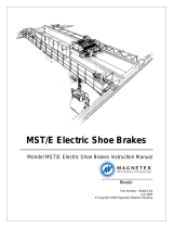
Fig. 1: SA
1. Brake Base 7. Armature Air Gap Indicator
2. Brake Arms 8. Pushrod Adjustment Nut
3. Brake Shoes 9. Torque Spring Bolts
4. Magnet Case 10. Coil Terminal Box
5. Armature 11. Brake Nameplate, Shown Right Hand Side of Brake
6. Pushrod 12. Manual Equalization Bolts/Shipping Bolts
9
2
87
10
6
1
12
3
5
11
4

SA Electric Shoe Brakes Instruction Manual
May 2019
Page 9 of 44
2 Application
For a given wheel diameter, the Association for Iron and Steel Technology (AIST) determines the
recommended torque, when applied to 30- and 60-minute series type and 1-hour and 8-hour continuously
rated shunt-type motors in steel mill applications. This is based upon experience and agreement within the
industry, but it is ultimately determined by each end user whether to follow recommendations or not.
When applied to four-quadrant drives or other applications where wheel heating can be accurately
predicted and the thermal load is relatively small, brakes can be provided with torque values in excess of
recommendations.
When the thermal load and wheel heating are relatively large and the load cycle requires a larger-than-
normal wheel size, as is frequently the case on crane bridge drives, brakes can be provided with torques
lower than recommendations.
For more demanding or corrosive environments, stainless steel hardware, National Electrical
Manufacturer's Association (NEMA)-grade enclosures and paint/surface treatments are available. A
wide range of brake wheels, OEM spare parts, special add-ons, and product options are available. Consult
Magnetek product brochures, Magnetek.com, and/or Magnetek customer service for more information.
All electromagnetic coils used in SA brakes are engineered by Magnetek. Coils are manufactured and
tested by skilled technicians to ensure reliability of thermal, electrical, and magnetic performance. The coil
is secured to the magnet case by thermosetting epoxy. The epoxy bonds directly to the interior of the
magnet case, which efficiently transfers heat out of the coil through this direct conduction path. The air gap
of the coil is easily determined by the air gap indicator atop the magnet case. When the air gap is
maintained within correct limits, the coil will responsively actuate the brake. A dust shield is fastened to the
magnet case to protect the interface of the armature and magnet from dust, debris, and possible magnetic
particles in the environment. Coil replacements are easily performed by swapping out the coil assembly via
one pin connection.
Brakes can operate between ambient temperatures of -40 to 158°F (-40 to +70°C) and in an altitude as
great as 9,800 ft (3,000 m).

SA Electric Shoe Brakes Instruction Manual
May 2019
Page 10 of 44
3 Description of Operation
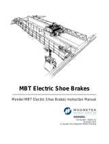
Braking torque is applied via dual torque springs. Heavy-duty compression springs push the armature and
magnet case, transmitting force through the brake linkage, and forcing the shoes against the wheel. The
default mode of the brake, when electric power is not supplied to the coil, is to apply braking torque to stop
and hold a load. This is referred to as “setting” the brake or described as “the brake is set.”
Fig. 2
1. Dual Torque Springs 2. Air Gap Open
12

SA Electric Shoe Brakes Instruction Manual
May 2019
Page 11 of 44
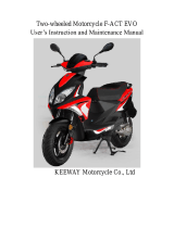
Electric power supplied to the coil cancels the brake’s ability to apply braking torque to the drive system.
When electric power is supplied, the armature is magnetically pulled toward the magnet case, the armature
air gap closes, the brake linkage moves the shoes completely off the wheel, and a clearance is developed.
This is referred to as “releasing” the brake or described as “the brake is released.”
Fig. 3
The magnetizing action of pulling in the armature to release the brake is also referred to as armature “pull-
in.” When power is removed from the coil, the magnetic force overcoming the torque springs disappears,
so the springs push out the armature and set the brake. This demagnetizing action of the armature is also
referred to as armature “drop-out.”
1. Magnetic Field Present 3. Shoe Release Clearance
2. Air Gap Closed
3
2
1

SA Electric Shoe Brakes Instruction Manual
May 2019
Page 12 of 44
3.1 Torque Springs
Braking torque is applied via dual torque springs. Torque springs are heavy-duty compression springs, so
the force output of the springs is proportional to the amount of spring compression. More spring
compression will make more braking torque. A measurement of the brake torque setting is made by
measuring the distance from the magnet case face to the underside of the bolt heads of the torque spring
bolts as shown in Fig. 4 on page 12.
Fig. 4
1. Torque Measurement
1

SA Electric Shoe Brakes Instruction Manual
May 2019
Page 13 of 44
Braking torque is adjusted via the torque spring bolts. There is one torque spring bolt for each torque
spring. Torque spring bolts are located on the exterior of the magnet case. Braking torque is increased by
“tightening” the bolt into the magnet case and decreased by “loosening” the bolt the other direction.
The two torque spring bolts must always be set equally during operation. The desired braking torque and
successful brake release may not be achieved if torque spring bolts are set unequally.
The torque spring bolts must always be set within the minimum and maximum limits in operation. Torque
spring bolts set below their minimum measurement will make the coil struggle to release the brake. Torque
spring bolts set above their maximum measurement will make the brake struggle to set within a typical
response time.
Fig. 5
Rated torque spring bolt settings (inch) and associated torques (lb-ft) for each brake size are shown in
Table 1 on page 14.

SA Electric Shoe Brakes Instruction Manual
May 2019
Page 14 of 44
Table 1: Torque Settings
3.2 Air Gap Indicator
With torque set within minimum and maximum limits, proper brake operation is further maintained by
measuring the air gap between the armature and magnet case, via the air gap indicator, and also
maintaining it within minimum and maximum limits. The air gap is measured only when the brake is set. The
minimum and maximum limits are stated physically on the air gap indicator, and in Table 2 on page 15. The
air gap is measured from the face of the indicator to the face of the armature feature.
Brake Setting
4"
DIMENSION 15/16" 1" 1-1/32" 1-1/16"
TORQUE 22 18 14 11
6"
DIMENSION 3/4" 7/8" 31/32" 1-1/16"
TORQUE 67 50 44 34
8"
DIMENSION 21/32" 23/32" 25/32" 15/16"
TORQUE 140 115 88 70
10"
DIMENSION 1-5/16" 1-3/8" 1-9/16" -
TORQUE 290 240 190 -
12"
DIMENSION 1-1/8" 1-1/4" 1-5/16" 1-3/8"
TORQUE 510 425 340 280
13"
DIMENSION 1-1/8" 1-1/4" 1-5/16" 1-3/8"
TORQUE 550 460 360 280
15"
DIMENSION 1-1/4" 1-5/16" 1-3/8" 1-7/16"
TORQUE 1125 960 750 560
16"
DIMENSION 1-1/4" 1-5/16" 1-3/8" 1-7/16"
TORQUE 1200 1000 800 600
WARNING
Always set the two torque spring bolts equally. Always keep the torque setting within minimum and
maximum bounds. Setting the torque outside the minimum and maximum bounds can result in
hazardous conditions that may lead to serious injury or death.

SA Electric Shoe Brakes Instruction Manual
May 2019
Page 15 of 44
Fig. 6
Table 2: Armature Air Gap Settings
If the air gap exceeds its maximum limit, the torque springs are no longer compressed enough. The
springs are outputting insufficient force, so the brake is developing torque less than the intended
magnitude. The excessive air gap creates more resistance for the coil to overcome and makes the brake
struggle to release. When the drive system moves a load in this condition the brake may not release. This
may cause the move to fail or may overheat and damage the brake and the drive system.
The air gap will change naturally during operation. The wear of friction linings during normal use will
increase the air gap. The thermal expansion of a brake wheel may decrease the air gap. A recent brake
1. Air Gap
BRAKE Minimum Air Gap Maximum Air Gap
4" 1/16" 7/64"
6" 1/16" 7/64"
8" 5/64" 1/8"
10" 5/64" 5/32"
12" 7/64" 11/64"
13" 7/64" 11/64"
15" 5/32" 1/4"
16" 5/32" 1/4"
1

SA Electric Shoe Brakes Instruction Manual
May 2019
Page 16 of 44
installation or adjustment may affect the air gap even after making proper adjustments. The air gap is
controlled via adjustments to the pushrod.
3.3 Pushrods
High-performance friction linings are bonded to the brake shoes and the thickness of the linings will
naturally diminish over time as the brake is used. As the lining material diminishes, the brake linkage will
naturally shift, causing the torque springs to decompress and the air gap to increase. Pushrod adjustments
must be performed to compensate for this phenomenon.
Pushrods are described as having a “length.” The pushrod length is the distance between the pushrod
adjustment nut and the pivot pin axis as shown in Fig. 7 on page 16.
Fig. 7
1. Pushrod Length
DANGER
Always keep the armature air gap within minimum and maximum bounds. Measure the air gap, then
make pushrod adjustments as necessary. Exceeding the maximum bound results in a hazardous
condition of insufficient or potentially zero braking power available to a load that may lead to serious
injury or death.
1

SA Electric Shoe Brakes Instruction Manual
May 2019
Page 17 of 44
The pushrod must decrease in length incrementally over the lifetime of a pair of friction linings to maintain
correct air gap and brake torque. When brake shoes are replaced, the pushrod must return to the
approximate length it was set to upon initial installation of the brake.
The pushrod controls the air gap, but the air gap must be maintained by periodic manual adjustment. An
adjustable nylon hex nut with a pushrod collar makes a connection between the magnet case and pushrod.
Adjustment of the nylon hex nut controls the pushrod length. At the other end of the pushrod is a non-
adjustable trunnion block, which never requires adjustment for normal operation and maintenance.
Fig. 8
NOTE: Only make pushrod adjustments per the procedure in Section 4.2 on page 21.
3.4 Shoe Equalization Bolts
The total available shoe clearance is proportional to the armature air gap. The greater the armature air
gap, the more clearance will be given to the brake shoes when the brake is released. The distribution of
the available shoe clearance between the two brake shoes is determined by the positions of the two
manual equalization bolts.
When the brake releases, the brake arms pivot about their connection to the brake base and away from
the wheel. The shoe equalization bolts act as stops for the brake arms. Given enough space to do so, a
brake arm will pivot away from the wheel and rest upon its equalization bolt. Raising the height of the bolt
head above the base will reduce the travel space available to that brake arm and therefore reduce the
clearance given to that brake shoe. One shoe equalization bolt, typically the bolt opposite the coil, should
be set to a position that limits the clearance given to that brake shoe, so that equal clearance is given to
the other shoe as well.
1. Adjustable Nylon Hex Nut 3. Pushrod Spring
2. Pushrod Collar
1
2
3

SA Electric Shoe Brakes Instruction Manual
May 2019
Page 18 of 44
As the friction lining material diminishes, the brake shoes will move closer to the wheel and the brake arms
will pivot further inward toward the brake wheel.
NOTE: When each pushrod length adjustment is made to compensate for lining wear, the
manual equalization bolts should also be adjusted to compensate for the inward shift of the
brake arms.
For adjustment procedure of the shoe equalization bolts, see Section 4.4 on page 23.
3.5 Hand Release Mechanism
A hand-release mechanism is not required for brake operation but is a useful option to install. A hand
release allows for mechanical release of the brake, which is very useful for various maintenance
procedures and other purposes.
To use the hand release, rotate the handle to release the brake. When the handle is not in use, the brake
operates as it would normally if there were no hand release installed at all.
The SA hand release is a non-latching, also known as self-resetting, type. The hand release can release
the brake but the handle must be maintained in position to maintain brake release.
Hand releases are easily installed on the right or left side of the brake.
3.6 Limit Switches
SA brakes can be used with limit switches to indicate brake set, brake release, or hand release.
Combinations of limit switches are also possible. The pushbutton-type limit switch provided by Magnetek
offers a rugged enclosure meant to withstand harsh environments while being extremely reliable and
requiring minimum maintenance.
Limit switches are attached to the magnet case via a bracket and actuated by adjustable screws. The
brake should be released and/or the hand release engaged before adjusting the actuating screws.
The “brake set” and “brake release” limit switches are actuated in the same way. The actuating screw is
attached to the armature via an adapter. The armature pulls in and mechanically actuates the limit switch.
The “hand release” limit switch is actuated when the hand-release handle is used to release the brake. The
actuating screw is attached to the handle, which moves toward the magnet case and actuates the limit switch.
Limit switches are easily installed on the left or right side of the brake.
Table 3: Pushbutton-Type Limit Switch Properties
Limit Switch Property Detail
EATON Cutler-Hammer ED50 Double Throw, Double Pole (2 N.O. – 2 N.C.)
Switch Body
Receptacle
Operating Head
E50SB
E50RB
E50DT1
Environmental Ratings NEMA 1, 3, 3S, 4, 4X, 6, 6P, 13, IP67
Conduit Entrance 1/2" NPT
Mechanical Life 10,000,000 operations minimum
Electrical Life 100,000 operations typical at full load
Ambient Temperature Range 14°F to 250°F (-10°C to 121°C)
Wire Size
Will accept AWG #18 though #12 (0.33 mm
2
through
3.31 mm
2
) single or stranded wire

SA Electric Shoe Brakes Instruction Manual
May 2019
Page 19 of 44
3.7 Other
Magnetek Engineering will supply any custom design that is required. Various special features such as
hydraulic and pneumatic overrides, lining wear measuring devices, custom coils, special enclosures,
stainless steel components, lockout/tagout devices, etc. can be made available upon request. If any
custom features are installed, consult the brake’s engineering drawing for supplementary instructions.

SA Electric Shoe Brakes Instruction Manual
May 2019
Page 20 of 44
4Adjustment
Adjustments to the quality of the brake wheel and limits for brake wheel runout are given below.
Table 4: Allowable Brake Wheel Properties
4.1 Manual Operation
To safely perform a brake installation, shoe replacement, coil assembly replacement, and other work
requires that the brake be released and reapplied without energizing the coil.
This is done by either using the hand release or adjusting the pushrod length to release and set the brake.
Brake Wheel Size
Minimum Brake
Wheel Diameter After
Resurfacing
1
Maximum Full Speed
Brake Wheel Runout
2
4"
6"
8"
10"
12"
13"
15"
16"
3.94"
5.94"
7.94"
9.92"
11.90"
12.90"
14.87"
15.87"
0.004"
0.006"
0.008"
0.010"
0.012"
0.013"
0.015"
0.016"
Notes:
1
Per the recommendations of AISE Technical Report No. 11, which only
apply for wheel sizes 8" and greater.
2
Evaluate brake wheel run-out at full speed.
DANGER
An armature air gap exceeding the maximum setting as physically stated on the air gap indicator will
result in loss of braking torque. Under no circumstances should the brake be allowed to function with
an air gap in excess of the maximum limit. Such operation can result in the loss of load control, which
can lead to serious injury or death.
/