Page is loading ...

SERVICE
MANUAL
hotor co*, ltd
TOKYO,JAPAN
P/N 99999- 20002

SERVICE
MANUAL
expert22 fl/ia http://rutracker.org
1
NISSAN
NISSAN HOTOft CO., LTD Hi • W0
TOKYO,JAPAN
P/N 99999-
20002

DATSUN
MODEL 411 SERIES
SERVICE
MANUAL
Hoeoe umx 3ah torrents.ru IMS'
NISSAN
NISSAN MOTOR CO., LTD.
OTEMACHI BLOG., OTEMACHI, CHIYODA-KU,
TOKYO,JAPAN
CABLE ADDRESS : "NISMO" TOKYO
PHONES : (216) 2311
expert22 http://rutracker.org

INT RODUC TION
This manual has been complies for purpose of assisting
DATSUN distributors and dealers for effective service and
maintenance of the Model P(L)411. Each assembly of the
major components
is
described in detail. In addition,
comprehensive instructions are given for complete dismantl-
ing, assembling and inspection of these assemblies.
It is emphasised that only genuine DATSUN Spare Parts
should be used as replacements.
DATSUN MODEL (L) 411 - U

CONTENTS
Page
MAJOR SPECIFICATIONS
ENGINE
i
Cooling System 3
Lubrication 8
SERVICE OPERATIONS 11
Rocker Mechanism 12
REMOVING & REFITTING 25
Operation with the Engine Removed 26
IGNITION TIMING 31
Distributor 31
Adjusting the Ignition Timing 31
FUEL SYSTEM 34
Carburetor 34
The Gasoline Tank 37
Fuel Strainer 40
Adjustment and Inspection of Engine 43
CLUTCH 48
TRANSMISSION 57
Cover of Transmission Case 58
Transmission Case 59
Extension of Transmission Case 65
Disassembly the Transmission Case (For 4 Stage Floor Shift) 72
CHASSIS
ss
FRONT AXLE 85
Disassembling the Front Hub 86
Indipendent Front Suspension 88
REAR AXLE 98
STEERING 112
BRAKE 119
Front Brake 120
Rear Brake 123
Hand Brake 126
ELECTRICAL SYSTEM 129
Alternator 130
Generator 132
Regulator 139
14 Items on Handling 142
Trouble Shooting List 143
Starter Motor 144
expert22 ajia http://rutracker.orq

DISMOUNTING & ASSEMBLING

MAJOR SPECIFICATION
OF
MODEL
41 1
SERIES
"— ____^MODEL
ITEM
~~
P(
L) 41
1-U
P(
L) 4 1
1-UT
WP(
L) 41
1-U
WP(L)41
1-UT
DIMENSIONS
Overall Length
3,995
mm
(157.3
in.)
3,995
mm
(157.3
in.)
DIMENSIONS
Overall Width
1,490
mm ( 58.7 in.)
1,490
mm ( 58.7 in.)
DIMENSIONS
Overall Height
1,440
mm ( 56.7 in.)
1,430
mm ( 56.3 in.)
DIMENSIONS
Wheel Base
2,380
mm (93.7 in.)
2,380
mm ( 93.7 in.)
DIMENSIONS
Room Space
Inner Length
Inner Width
.
Inner Height
1,710
mm ( 67.3 in.)
1,704
mm ( 67.1 in.)
DIMENSIONS
Room Space
Inner Length
Inner Width
.
Inner Height
1,240
mm (
48
.8 in-)
1,240
mm ( 48.8 in.)
DIMENSIONS
Room Space
Inner Length
Inner Width
.
Inner Height 1,130
mm ( 44.5 in.)
1,130
mm ( 44.5 in.)
DIMENSIONS
Tread
Front
,Rear
1,206
mm ( 47.5 in )
1,206
mm ( 47.5 in.)
DIMENSIONS
Tread
Front
,Rear 1,198
mm ( 47.2 in.)
1,198
mm ( 47.2 in.)
DIMENSIONS
Min. Road Clearance
175
mm ( 6.9 in.)
175
mm ( 6.9 in.)
DIMENSIONS
Overhang
to the
Front
End
without bumper
S05
mm ( 23.8 in.)
605
mm ( 23.8 in.)
DIMENSIONS
Overhang
to the
Rear
End
without bumper
950
mm ( 37.4 in.)
947
mm ( 37.3 in.)
WEIGHT
Vehicle Weight
885
kg
(1951
lb.)
960
kg
(2116
lb.)
WEIGHT
Distribution
Front
Rear
505
kg
(1113
lb.)
500
kg
(1102
lb.)
WEIGHT
Distribution
Front
Rear
380
kg ( 838 lb.)
460
kg
(1014
lb.)
WEIGHT
Vehicle Gross Weight
f Front
Distribution
I
(.Rear
1,160
kg
(2557
lb.)
1,235
kg
(2723
lb.)
WEIGHT
Vehicle Gross Weight
f Front
Distribution
I
(.Rear
600
kg
(1323
lb.)
595
kg
(1312
lb.)
WEIGHT
Vehicle Gross Weight
f Front
Distribution
I
(.Rear
560
kg (1234 lb.)
640
kg
(1411
lb.)
WEIGHT
Height
of
Gravity Center
580
mm ( 22.8 in.)
580
mm ( 22.8 in.)
WEIGHT
Proportion
of
Front Tire
with load
51.7
%
48.2
%
WEIGHT
Max. Inclination Right
Angle Left
46
46
WEIGHT
Max. Inclination Right
Angle Left
46
46
(i)

DATSUN
^ MODEL
ITEM —
P(
L) 41
1-U
P(
L) 41
1-UT
WP(
L) 41
1-U
WP(L)41 1-UT
w
o
£
Max. Speed
140 km/H (87 MPH) 140 km/H (87 MPH)
w
o
£
Fuel Consumption
18.5 km/£
18.5 km/£
§
K
O
Grade Ability sinfl
0.375, 0.417 (-UT)
0.334, 0.391 (-UT)
fe
w
w
ft
Min. Turning Radius
5
.0 m (16.4 ft.) 5.0 m (16.4 ft.)
fe
w
w
ft
Brake Stopping Distance (50 km/h'
13
5 m (44.3 ft.) 13.5 m (44.3 ft.)
Model
J
Make
NISSAN MOTOR CO., LTD.
Classification
GASOLINE ENGINE
Cooling System
WATER FORCED CIRCULATION
No. of Cylinder & Arrang.
4 IN LINE
Cycle
4
Combustion Chamer
BATHTUB TYPE
Valve Arrangement
OVER HEAD VALVE
Bore x Stroke
73 x 77.6 mm (2 .874 x 3.055 in.)
Displacement
1299 c.c. (79.27 cu.in.)
w
y
Compression Ratio 8.2
a
o
fc
w
Compression Pressure 11.5/350 kg/cm
2
(r.p.m.)
a
o
fc
w
Max. Exploding Pressure
48/3600 kg/cm
2
(r.p.m.)
Max. Mean Effective Press
9.7/28000 kg/cm
2
(r.p.m.)
Max. B.H.P. (SAE) 67/5200 HP/r.p.m.
Max. Torque (SAE)
76 .7/2800 ft-lb/r.p.m. (10.6/2800 kg-m/r.p.m.)
Length x Width x Height
597 x 575 x 690 mm (23.1 x 22.6 x 26.5 in.)
Weight
139 kg (306 lb.)
Piston Type SPLIT SKIRT TYPE
Piston Material LO
-EX
(2)

MAJOR SPECIFICATION
ITEM
MODEL
P (
L) 41
1-U
P(
L) 4 1 1
-UT
WP(
L) 4 1
1-U
WP(L)41 1-UT
No. of
Piston Ring
Pressure
Oil
2
1
' Inlet Open
14° B
.T.D.C.
w
Valve Timing •
Inlet Close
50° A
B.D.C.
U
O
£
w
Valve Timing •
Exh. Open
52° B
.B.D.C.
U
O
£
w
. Exh. Close
12° A
T.D.C.
Valve
Intake
0.35 mm (0.014 in.)
Clearance
, Exhaust
0.35 mm (0.014 in.)
Starting Method
MAGNETIC STARTING SYSTEM
K
Type
N41 (14MZ), N50 (2SMB) 1 each
w
H
H ,
<
Voltage
12V
CQ
Capacity
40, 50 A.H.
Ground Polarity
NEGATIVE
Type
AC300/12WR
Make
MITSUBISHI
K
O
H
Generating Method
ALTERNATOR
<1
«
W
Voltage
12V
W
O
Capacity
300 W
Voltage Regulator
RL -2B1
K
W
H
«
<
Type
S114-92
K
W
H
«
<
Make
HITACHI
H
Voltage & Power
12-1.
4V-HP
S
w
H
Irt
—
K
W
Ignition Method
BATTERY-
-COIL TYPE
S
w
H
Irt
—
K
W
Ignition Timing
8° /600 B.T.D.C./r.p.m.
g <
Firing Order
1-3 -4-2
(3)

DATSUN
ITEM
MODEL
P(L)41 1-U
P(
L) 41
1-UT
WP(L)4
1
1-U
WP(L)41 1-UT
Ignition Coil
Type
C1Z-18
Ignition Coil
Make
HITACHI
Distributor
Type
D411-53
Distributor
Make
HITACHI
Distributor
Ign.Timing
Advance System
VACUUM AND GOVERNOR
Type
B
-6E
Spark Plug
Make
NGK
Spark Plug
Thread
14 mm (0.551 in.)
w
Gap
0.
7
~0.8 mm (0.0275 ~0.0315 in.)
s
hJ
o
Type
D2630A-5A
CO
<
O
Make
NIHONKIKAKI
§
w
H
CO
>H
Throttle
Valve Bore
P.
26 mm
S.
30 mm
M
S3
o
Venturi Size
20 mm
27 mm
h-1
H
h—1
Z
Carburetor
Main Jet
#92 #140
O
t
Slow Jet
#48 # 48
Pump Jet
#45
Power Jet
#40
Air Draught
DOWN
Air Cleaner
Type & No.
PAPER TYPE 1 each
Air Cleaner
Make
TSUCHIYA
Fuel Pump
Type
DIAPHRAGM
Fuel Pump
Make
SHOWA, KYOSAN
Capacity of Fuel Tank
41^ r (10.8 U.S.gal.)
LUB-
RICA-
TION
Lubrication Method
FORCED PRESSURE TYPE
(4)

MAJOR SPECIFICATION
—MODEL
ITEM
P (
L) 41
1-U
P(
L) 41
1-UT
WP(
L) 41
1-U
WP(L)41
1-UT
LUBRICATION
Oil Pump Type
TROCHOID TYPE
LUBRICATION
Oil Filter
FULL FLOW TYPE (CARTRIDGE TYPE)
LUBRICATION
Oil
Pan
Capacity
2.9
£
r (0.76
U.S.gal.)
COOLING
SYSTEM
Type
WATER COOKING CLOSED TYPE
COOLING
SYSTEM
Radiator
CORRUGATED
FIN AND
TUBE TYPE
COOLING
SYSTEM
Cooling Water Capacity
5.4
£r
(1.43
U.S.gal.)
COOLING
SYSTEM
Water Pump Type
CENTRIFUGAL TYPE
COOLING
SYSTEM
Thermostat
PELLET TYPE
CLUTCH
Type
SINGLE
DRY
DISC HYDRAULIC OPERATION
CLUTCH
No.
of
Plate
1 (FACING
2)
CLUTCH
Out.
dia x In. dia x
Thickness
200
x
130
x 3.5 mm
(7.87
x
5.12
x
0.138
in.)
CLUTCH
Total Friction Area
181
x 2 cm
2
(28.06
x 2
sq.in.)
CLUTCH
In.
dia. of
Operating Cylinder
19.05
mm
(3/4
in.)
CLUTCH
In.
dia. of
Master Cylinder
15.87
mm
(5/8
in.)
TRANSMISSION
Type
3 FORWARD,
1
REVERSE
ALL SYNCHROMESHED
ON FORWARD GEARS
4 FOREARD,
1
REVERSE
SYNCHROMESHED
ON
2ND,
3RD, 4TH
TRANSMISSION
Gear Shift Method
REMOTE CONTROL
FLOOR SHIFT
TRANSMISSION
Oil Capacity
1.7 £(0.45 US.gal.)
2.2
£
(0.58
U.S.
gal.)
TRANSMISSION
Gear Ratio
1st
3.197 3.945
TRANSMISSION
Gear Ratio
2nd
1.725 2.402
TRANSMISSION
Gear Ratio 3rd
1.000 1.490
TRANSMISSION
Gear Ratio
4th
1.000
TRANSMISSION
Gear Ratio
Reverse
4.125
5.159
PROPELLER
SHAFT
1st Length
x
Out.dia
x In dia.
1222
x
71
x
67.8
mm
PROPELLER
SHAFT
Type
of
Universal Joint
SPICER TYPE
FINAL
GEAR
Gear Type
HYPOID
(5)

DATSUN
ITEM
——MODEL
P( L)4
1
1-U
P(
L) 4 1
1-UT
WP(L)41 1-U
WP(L)41 1-UT
£
ss
E o
Gear Ratio
4 375
P
(
L
)
411
"
U
4 m
(op
3889
, P(L)411-UT
4
'
375
WP(L)411-U
4
-
111
(°
P
-
3889
> WP(L)411-UT
K
<
W
Housing Type
BANJO
O
Cn
Type & No. of Gear
STRAIGHT BEVEL PINION 2 each
Pn
HH
Q
Oil Capacity
1 £(0.26 U.S.gal.)
Type
RECIRCULATING BALL TYPE
2
W
H
in
Gear Ratio
15.0
CO
O
Steering J
n
36°
£
H-1
K
W
Angle
lout
28° 36'
W
H
C«
Steering Wheel Dia.
405 mm (15.95 in.)
Oil Capacity 0.33 £ (0.087 U.S.gal.)
Wheel Arrangement
2 FRONT, 2 REAR
W
o
H-1
>
W
Q
a
Front Axle Type
WISHBONE BALL JOINT TYPE
W
o
H-1
>
W
Q
a
Toe--in
3 mm
W
o
H-1
>
W
Q
a
Camber
1
0
45'
£
hH
Caster
0
«
Inclination Angle of King Pin
6 ° 15'
Rear Axle Type
SEMI-FLOATING TYPE
Type
FRONT:
2
LEADING; REAR: LEADING AND TRAILING
Lining Dimension
(Width x Thickness
x Length)
r
40 x 4.5 x 215 mm (1.575 x 0.177 x 8.465 in.)
§
w
Lining Dimension
(Width x Thickness
x Length)
u.
40 x 4.5 x 215 mm (1.
575 x 0.177 x 8.465 in.)
w
H
M
>H
<
«
PQ
Total Braking Area
r
351 cm2 (54.4 in2)
CQ
w
a
W
U
HH
>
Total Braking Area
u.
351 cm
2
(54.4 in
2
)
<
Oh
m
K
W
M
In.dia. of Brake
F. 228.6 mm (9.0 in.)
Drum
R.
228.6 mm (9.0 in.)
(6)

MAJOR SPECIFICATION
-——-—_MODEL
ITEM
P(
L) 4 1
1-U
P(L)41
1-UT
WP(
L) 4 1
1-U
WP(L)4
1
1-UT
BRAKE SYSTEM
SERVICE BRAKE
OIL BRAKE
In.dia.
of
Master
Cylinder
22.22
mm
(0.8748
in.)
BRAKE SYSTEM
SERVICE BRAKE
OIL BRAKE
In.dia.
of
Wheel
F
'
Cylinder
R.
25.40
mm
(1.000
in.)
BRAKE SYSTEM
SERVICE BRAKE
OIL BRAKE
In.dia.
of
Wheel
F
'
Cylinder
R.
23.81
mm
(0.9374
in.)
BRAKE SYSTEM
SERVICE BRAKE
OIL BRAKE
Max.
Oil
Pressure
115 kg/cm
2
(1636
lb/in
2
)
BRAKE SYSTEM
PARKING
BRAKE
Type
MECHANICAL
FOR
REAR WHEEL
BRAKE SYSTEM
PARKING
BRAKE
Lining Dimension
40
x 4.5 x 215 mm
(1.575
x 0.177 x
8.465
in.)
BRAKE SYSTEM
PARKING
BRAKE
Total Braking Area
351
cm
2
(54.4
sq.in.)
BRAKE SYSTEM
PARKING
BRAKE
In.
dia. of
Drum
228.6
mm (9.0 in.)
SUSPENSION
Front Suspension Type
INDEPENDENT SUSPENTION WITH COIL SPRING
SUSPENSION
Coil (Wire
dia. x
Coil
dia. x
Free Length
- No. of
Coils)
R.H.
CAR L.H. CAR
14.2
x 94 x
ffflfl-8.5,
14.2 x 94 x
325-8.5
o^5(L)
SUSPENSION
Rear Suspension Type
LONGITUDINAL SEMI-ELLIPTENG SPRING
SUSPENSION
Spring Size (Length
x
Width
x
Thickness
- No.)
6—2
1200
x 60 x
c
"
5-2
1200
x 60 x
6
~l
5-Z
SUSPENSION
Shock Absorber
F.
Shoe k Abs orbe r
R.
TELESCOPIC DOUBLE ACTION
SUSPENSION
Shock Absorber
F.
Shoe k Abs orbe r
R.
TELESCOPIC DOUBLE ACTION
SUSPENSION
Stabilizer
F.
TORSION
BAR
TYPE
i
<«
a
w
5
H
Tire Size
F
'
R.
5.60
- 13 - 4P
5.60
- 13 - 4P
LAMPS
Head Lamp (Sealed beam)
12V-37.5/50W
x 2
LAMPS
Width Indicators
12V-
8W x 2
LAMPS
Tail Lamps
12V-
8W x 2
LAMPS
License Plate Lamps
12V-
8W x 2
LAMPS
Stop Lamps
12V-25W
x 2
LAMPS
Reverse Lamps
12V-25W
x 1
LAMPS
Room Lamps
12V-
5W x 1
(7)

DATSUN
(8)

MODEL P(L) 411-U
RUNNING PERFORMANCE CURVE
Final gear ratio
4. 375 (35/8)
1st speed ratio 3. 197
2nd speed ratio
. 725
3rd speed ratio
1.000
4th speed ratio
Gross vehicle weight
1,160 kg
Max. grade ability tan 0=0. 382(sm0=O. 357)
Tire effective radius 0. 287 m
Max. torque (SAE)
10. 6m-kg/2i00r. p m.
Max. BHP (SAE)
67HP
/
5200r. p. m.
0 10 20 30 40 50 60 70 80 90 100 110 120 130 140 150 160
CAR SPEED (km/h) —
MODEL J ENGINE
PERFORMANCE CURVE
ENGINE SPEED (x 10
2
r. p. m.)

I
CL,
M
s
'u
Q
a
a
PS
MODEL WP(L) 411-UT
RUNNING PERFORMANCE CURVE
MODEL P(L) 411-UT
RUNNING PERFORMANCE CURVE
600
500
400
300
50%
Final gear ratio
4. Ill
1st speed ratio 3.945
2nd speed ratio 2.403
3id speed ratio
1.490
4th speed ratio
1.000
Gross vehicle weight
1, 235 kg
Max. grade ability
tan 0=0. 425(sin0=O. 391)
Tire effective radius
0. 287 m
Max. torque (SAE)
10. 6m-kg/2800r. p. m.
Max. BHP (SAE)
67HP/5200r. p. m.
45^
200
100
5000
0 10 20 30 40 50 60 70 80 90 100 110 120 130 140 150 160
Car Speed (km/h) f—
3000
4000
2
O
P
D
O
>
w
pi
a
2
3
3
2000
500
i
%
o
CU
c
•c
Q
300
PS 200
3
Bfi
100
Final gear ratio
4.111 |
1st speed ratio
3.945
2nd speed ratio
2.403
3rd speed ratio
1. 490
4th speed ratio
1.000
Gross vehicle weight
1,160 kg
Max. grade ability
tan 0=0. 459(sin 0=0. 417)
Tire effective radius
0. 287 m
Max. torque (SAE)
10, 6m-kg/ 2800r. p. m.
Max. BHP (SAE)
67HP/ 5200r. p. m.
50%
45%
5000
I.
s
4000 d
2
O
P
D
O
gi
OS
w
Z
C3
2
w
3000
2000
1000
0 10 20 30 40 50 60 70 80 90 100 110 120 130 140 150 160
Car Speed (kg/h) /—._

ENGINE
ENGINE
The engine is of monobloc construction, and
the valve are set in line in the cylinder head and
are operated by rockers and push rods from the
camshaft in the left hand side of the engine.
The camshaft, running in three steel backed
whitemetal bearings, is chain-driven and has a
rubber chain tenssioner.
The distributor and oil pump are driven
from the camshaft.
The pistons are the split skirt type of
aluminum alloy, and carry two compression
rings and a slotted oil control ring.
The piston pins are bolted in connecting
rods, which have steel backed lead and copper
alloy, changeable big end bearings.
A counter balanced crankshaft is fitted. The
end thrust on this component is taken by special
washers at the center main bearing. The
centrifugal water pump and cooling fan are
driven by the generator belt.
GENERAL SPECIFICATIONS
Engine type J type
No. of Cylinder 4
Bore (mm) 73 mm
Stroke 77.6 mm
Volume 1.299
Max. brake horse power 67 HP. at 5200 r.p.m.
Torque 10.6 kg-m at 2800 r.p.m.
Firing order 1-3-4-2
Valve arrangement Overhead valve, push rod type
Compression pressure 163 lbs.per sq.in. (11.5 kg/cm
2
) at 350 r.p.m.
Compression ratio 8.2 :1
- 1 -

DATSUN
ENGINE-RIGHT SIDE
ENGINE-LEFT SIDE
- 2 -

ENGINE
COOLING SYSTEM
An efficient cooling system is of major
importance to ensure the satisfactory running
of the engine and it is therefore necessary to
pay particular attention to its maintenance.
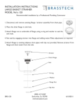
Description
The cooling system is maintained by water
pump circulation, combined with an efficient fan
cooled radiator and thermostat.
The system is pressurised and the reliei
ralve, incorporated in the radiator filler cap,
controls the pressure at approximately 0.4 kg
per sq. cm. Do not remove the filler cap if
the temperature of the coolant is above boiling
point or if the engine is running. Topping-up
should only be required occasionally to replace
water lost through the overflow pipe. Top-up
when the engine is cold, and if possible use
clean soft water.
Fig. 1 Radiator
Fill to within l/2" of the bottom of the filler
plug well. Overfilling when the engine is cold
may cause water to flow through the overflow
pipe. The capacity of the system is approxi-
mately 5.2 litres.
- 3 -

DATSUN
Thermostat
In order to ensure maximum efficiency, it
is essential to keep the engine operating
temperatures within certain limit. To assist
this a pellet tyep thermostat is fitted, being
located in the water outlet at front of the
cylinder head.
Pellet type thermostat works by the principle
of rapid variation of solution of wax.
Fig. 2 Pellet Type Thermostat
The devise consists of metalic pellet, filled
with the wax, which controls a mash-room valve
by solution of wax.
When the engine is cold this valve is closed
and on starting the engine the flow of water to
the radiator is temporarily restricted.
Due this, the temperature of the water in the
cylinder head and cylinder jackets will quickly
rise, thus ensuring rapid warming up.
The heat so generated will gradually press
up the piston by shrinkage of synthetic rubber
sleeve so opening the valve, and ultimately
permitting a full flow of water to the radiator.
The thermostat itself is detachable; therefore,
should be occasion arise, it can be removed
from its housing and the hose reconnected to
avoid laying up the car.
The thermostat opening is set by the
manufacturer and can not be altered.
During decabonising it is policy to test this
opening by immersing the thermostat in water
raised to requisite temperature. The valve
should open under these conditions, but if it
fails to open a new unit should be fitted.
Overheating
Overheating may be caused by a slack fan
belt, excessive carbon deposit in the cylinders,
running with the ignition too far retarded,
incorrect carburetor adjustment, failure of the
water to circulate or loss of water.
Fan Belt Adjustment
The fan is driven from the crankshaft by
a
,r
V" belt, this also driving the alternator.
A new belt can be fitted by first loosening
the clamp bolts (Fig. 3), which hold the dynamo
in position, and moving the dynamo towards the
engine. Slide the belt over the fan and onto the
fan pulley.
Fig. 3 Fan Belt Adjustment
Part No.
Bated Temperature
Standard
21200 61001
Open at 76.5 °C ± 1.5'°C
Open fully at 90 ±1.5 °C
Optional for cold district
21200 61001
Open at 82 °C±1.5°C
Open fully at 95 ±1.5 °C
- 4 -
/