Page is loading ...

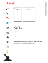
UNISUN SLIM
ITALIANOENGLISH
ISTRUZIONI PER L’INSTALLATORE E IL MANUTENTORE
INSTALLATION AND SERVICING MANUAL

3
Installation Instructions
Technical Characteristics
General information
Maintenance instructions
ENGLISH
Attention: this manual contains instructions for the exclusive use of the professionally qualied installer
and/or maintenance engineer in compliance with the applicable legislation in force.
The user is NOT permitted to service this appliance.
The manufacturer will not be held liable in case of damage to persons, animals or objects resulting from
failure to comply with the instructions contained in the manuals supplied with the boiler.
2 TECHNICAL CHARACTERISTICS AND DIMENSIONS ...................................................................................8
2.1 Technical characteristics .........................................................................................................................8
2.2 Main components view and dimensions ..................................................................................................8
2.3 Available ow rate / pressure diagram ....................................................................................................9
2.4 Operating data .........................................................................................................................................9
4 SOLAR CONTROL UNIT MAINTENANCE INSTRUCTIONS .........................................................................20
4.1 Wiring diagram ......................................................................................................................................23
3 INSTRUCTIONS FOR THE INSTALLER ........................................................................................................ 11
3.1 General warnings .................................................................................................................................. 11
3.2 Installation regulations ........................................................................................................................... 11
3.3 Packaging .............................................................................................................................................. 11
3.4 Positioning the appliance ......................................................................................................................12
3.5 Connections ..........................................................................................................................................12
3.6 Filling the solar circuit - cylinder - system ..............................................................................................14
3.7 Electrical connections ............................................................................................................................18
3.8 Commissioning ...................................................................................................................................... 19
1 GENERAL INFORMATION ...............................................................................................................................4
1.1 General warnings ....................................................................................................................................4
1.2 Symbols used in the manual ...................................................................................................................5
1.3 Appropriate use of the appliance .............................................................................................................5
1.4 Information to provide to the user ............................................................................................................5
1.5 Safety warnings ....................................................................................................................................... 6
1.6 Technical data plate .................................................................................................................................7
1.7 Water treatment ....................................................................................................................................... 7

4
1
GENERAL INFORMATION
In the event of failure and/or malfunctioning of the
appliance, switch it off and do not try to repair it or
intervene on it directly. Contact only personnel quali-
ed in compliance with law.
Any product repairs must be performed solely by
personnel authorised by Unical, using original spare
parts only. Failure to comply with the above can
compromise the safety of the appliance and void
the warranty.
To guarantee appliance efciency and its correct
operation, yearly maintenance must be performed
by qualied personnel.
Should you decide not to use the appliance, parts
entailing potential sources of hazard must be made
safe.
Before commissioning an appliance that has not
been used, wash the domestic hot water production
system, making the water ow until it has been fully
replaced.
Should the appliance be sold or transferred to a new
owner or if you move and leave the appliance, always
make sure that the instruction manual accompanies
it in order to be consulted by the new owner and/or
installer.
Only original accessories must be used for all appli-
ances with optionals or kits (including electric).
This appliance is intended solely for the use for which
it was expressly designed.
Any other use is to be considered improper and
therefore dangerous.
1.1 - GENERAL WARNINGS
The instruction manual is an integral and essential
part of the product and must be kept by the user.
Read the warnings contained in the manual carefully,
since they provide important information about safe
installation, use and maintenance.
Keep the manual in a safe place for future reference.
Your appliance must be installed and serviced
professionally in compliance with the standards
in force according to the manufacturer's instruc-
tions, by legally qualied and certied personnel.
Systems for the production of domestic hot wa-
ter MUST be constructed entirely with compliant
materials.
By professionally qualied personnel we mean:
personnel with specic technical skill in the eld
of heating system components for civil use, do-
mestic hot water production and maintenance.
Personnel must have the qualications envis-
aged by current legislation.
Incorrect installation or improper maintenance
may cause personal injuries, harm to animals
or property damage, for which the manufacturer
will not be held liable.
Before performing any cleaning or maintenance,
disconnect the appliance from the energy mains by
acting on the switch of the system and/or through
the specic cut-off devices.

5
1.2 - SYMBOLS USED IN THE MANUAL
Pay special attention when reading this manual to the parts marked by the symbols:
NOTE!
Tips for
the user
CAUTION!
Possible dangerous
situation for the product
and the environment
DANGER!
Serious danger to
safety and health
1.3 - APPROPRIATE USE OF THE APPLIANCE
The UNISUN SLIM appliance was built according to the latest technologies and in ac-
cordance with the applicable technical safety regulations.
Nonetheless, if improperly used, dangers could arise for the safety and life of the user
and other persons or damage to the equipment or other objects.
The appliance is designed to work in solar systems and for domestic hot water produc-
tion.
Any other use is considered improper.
UNICAL AG S.p.A. will not be held liable for any damage resulting from improper use.
Use according to the intended purposes also includes strict compliance with the in-
structions in this manual.
The user must be instructed concerning the use and operation of his heating system, in particular:
• Deliver these instructions to the user, as well as other documents concerning the appliance
inserted in the envelope inside the packaging. The user must keep this documentation safe
for future consultation.
• Please note that, in compliance with the standards in force, the inspection and maintenance of
the appliance must be carried out in compliance with the regulations and frequency indicated
by the manufacturer.
• Should the appliance be sold or transferred to a new owner or if you move and leave the ap-
pliance, always make sure that the instruction manual accompanies it in order to be consulted
by the new owner and/or installer.
The manufacturer will not be held liable in the event of damage to persons, animals or
objects resulting from failure to comply with the instructions contained in this manual.
1.4 - INFORMATION TO PROVIDE TO THE USER
NOTE!
For further details,
refer to the Technical Information:
http://www.unicalag.it/prodotti/
domestico-50/solare-termico/
unisun/799/unisun-slim

6
1.5 - SAFETY WARNINGS
CAUTION!
The appliance may only be used by adults after reading the installation and servicing
manual thoroughly.
Children must be supervised to prevent them from playing or tampering with the ap-
pliance
CAUTION!
The appliance must be installed, adjusted and maintained by professionally qualied
personnel, in compliance with the standards and provisions in force. Incorrect instal-
lation can cause damage to persons, animals and objects for which the manufacturer
cannot be held responsible.
DANGER!
NEVER attempt performing maintenance or repairs on the appliance on your own initia-
tive.
Any work must be done by professionally qualied personnel. We recommend stipulat-
ing a maintenance contract.
Insufcient or irregular maintenance can jeopardise the operating safety of the appli-
ance and cause damage to persons, animals and objects for which the manufacturer
cannot be held responsible.
Changes to the parts connected to the appliance (once the appliance installation is
complete)
Do not modify the following parts:
- water and electrical current lines
- the safety valve and the drain pipe
- the construction parts which affect the operating safety of the appliance
Attention!
To tighten or loosen the screwed ttings, use only appropriate xed spanners.
Non-compliant use and/or inappropriate tools can cause damage (e.g. water or gas leakage).
Explosive and easily ammable substances
Do not use or store explosive or easily ammable materials (e.g. petrol, paints, paper) in the
room where the appliance is installed.
DANGER!
Do not use the appliance as a supporting base for objects.
In particular, do not place receptacles containing liquids (Bottles, Glasses, Jars or Detergents)
on top of the appliance.
If the appliance is installed inside a housing, do not insert or rest other objects inside this housing.

7
General information
ENGLISH
1.6 - TECHNICAL DATA PLATE
The data plate is afxed to the right
side of the appliance
1.7 - WATER TREATMENT
The treatment of the supply water is
designed to prevent inconveniences
and maintain the functionality and
efciency of the generator over time.
The ideal water pH in heating systems
must be within:
VALUE MIN. MAX.
PH 6.5 8
Hardness [°fr] 9 15
To minimise corrosion, it is crucial to
use a corrosion inhibitor; in order for
it to work properly, the metal surfaces
must be clean.
(see system protection ACCESSO-
RIES sect. in domestic price list)
CAUTION!
ANY DAMAGE TO THE APPLIANCE
CAUSED BY THE FORMATION OF
FOULING OR BY CORROSIVE WATER
WILL NOT BE COVERED BY THE WAR-
RANTY.
NOTE!
Further details in the ‘‘Technical
Information’’ section on the boiler
page of the www.unicalag.it website

8
2
TECHNICAL CHARACTERISTICS AND
DIMENSIONS
2.1 - TECHNICAL CHARACTERISTICS
2.2 - VIEW WITH THE INDICATION OF THE MAIN COMPONENTS AND DI-
MENSIONS
NOTE!
Further details in the ‘‘Technical
Information’’ section on the boiler
page of the www.unicalag.it website
KEY
No. W.D. Description
1 Manual air relief valve
2 S3 Cylinder sensor pit
3 150-litre water cylinder
4 Integration heating element
pit
5 Solar panel return thermom-
eter / tap
6 Solar Control Unit
7 Thermostatic mixing valve
8 Solar circuit pressure gauge
9 6-litre expansion vessel
10 18-litre expansion vessel
11 Pre-sheared cap for Supply
cable outlets - relay kit - inte-
gration heating element kit.
12 Pre-sheared cap for Solar
system Flow/Return outlets
13 Cylinder drain valve
14 S2 Cylinder sensor pit
C
(cyl)
Domestic hot water
outlet
G ½
C *
(boil)
(mix)
Hot inlet from boiler
(integration)
G ½
F *
(boil)
Cold water inlet to
boiler (integration)
G ½
F
(acq)
Aqueduct cold water
inlet
M
(ss)
Solar system ow G ¾
R
(ss)
Solar system return G ¾
Svb Cylinder safety drain valve
Svs Solar system safety drain
valve
W.D. = WIRING DIAGRAM KEY
see para. 4.5
* LOOP pipe to be removed if the ap-
pliance is connected to an integration
boiler.

9
Technical Characteristics
ENGLISH
View from above
View from below
Right-hand viewLeft-hand view

10
2.4 - TECHNICAL DATA PLATE
Maximum solar operating temperature °C 95
Minimum solar operating temperature °C 30
Solar expansion vessel total capacity l 18
Minimum solar circuit pressure bar 1.5
Maximum solar circuit pressure bar 6
DHW cylinder expansion vessel total capacity l 6
Minimum domestic hot water circuit pressure bar 0.5
Maximum domestic hot water circuit pressure bar 6
Voltage/Frequency electric power supply V/Hz 230/50
Maximum absorbed output W 60
Protection rating IP 20
CYLINDER
Total Capacity l 147.6
Maximum DHW operating pressure bar 10
Maximum heat exchanger operating pressure
bar 6
Maximum cylinder operating temperature
°C 95
Lower heat exchanger surface area
m ² 1.2
Max. absorbed output
kW 3.6
10/45°C DHW production (heat. 80/60)
l/h 900
2.3 - DOMESTIC HOT WATER PRODUCTION
Without integration (only solar storage tank)
Temperature of
Cylinder
70°C
Temperature of
inlet water
10°C
Temperature of
delivery
45°C (Mixed Water)
Flow rate 12 l/min
After 17’ approx. 204 l at 45°C
(Flow rate 12 l/min - solar collector temp. 70°C - Mix T 45°C)
Time (sec)
Temperature (°C)

11
Installation Instructions
ENGLISH
3
INSTALLATION INSTRUCTIONS
CAUTION!
This appliance is intended solely for
the use for which it was expressly
designed. Any other use is to be
considered improper and therefore
dangerous.
This appliance heats water at a tem-
perature lower than the atmospheric
pressure boiling temperature.
Before connecting the appliance, have
professionally qualied personnel:
3.1 - GENERAL WARNINGS
3.2 - INSTALLATION REGULATIONS
It must be installed by a professionally qualied
technician, who shall take the responsibility of
observing all local and/or national laws published
in the ofcial journal, as well as the applicable
technical standards.
NOTE!
For further details relating to the
standards, rules and regulations
for safe installation of the thermal
unit, refer to the section "Technical
Information" on the boiler page of
the www.unicalag.it website
NOTE!
Further details in the
‘‘Technical Information’’ section on
the boiler page of the
www.unicalag.it website
Thoroughly wash all the piping of the
system to remove any residue or im-
purities which could jeopardise proper
operation of the appliance, even from a
hygienic point of view.
3.3 - PACKAGING
The appliance is supplied completely assembled in
a sturdy cardboard box.
After having removed the appliance from
the packaging, make sure that the supply
is complete and undamaged.
The packaging elements (cardboard
box, straps, plastic bags, etc.) must be
kept out of the reach of children as
they are potential sources of danger.
Unical AG S.p.A. will not be held liable
for damage to persons, animals or ob-
jects due to failure to comply with the
instruction above.
As well as the appliance, the packaging contains:
A DOCUMENTATION ENVELOPE
- Instruction manual for the installer and mainte-
nance engineer
- Warranty
- 2 Spare parts forms
UNISUN SLIM
P
depth
(mm)
L
width
(mm)
H
height
(mm)
Net
Weight
(kg)
Gross
Weight
(kg)
500 800 2250 101 122

12
When choosing where to install the device, adhere
to the following safety indications:
- Position the appliance in areas protected from
frost.
- Avoid installation in rooms with a corrosive or very
dusty atmosphere.
- The appliance must only be installed on a vertical
and solid wall which can support its weight.
3.4 - POSITIONING THE APPLIANCE
Clearance
3.5 - CONNECTION
The mains pressure must be within 1 and 3
bar (in the event of greater pressure install
a pressure reducer).
C (boil) (mix) * Hot inlet from boiler
(integration)
1/2’’
F (boil) * Cold water inlet to boiler
(integration)
1/2’’
C (cyl)
Domestic hot water outlet
1/2’’
F (acq)
Aqueduct cold water inlet
1/2’’
M (ss) ** Solar system ow 3/4’’
R (ss) ** Solar system return 3/4’’
(*) LOOP pipe to be removed if the appliance is
connected to an integration boiler.
(**) The piping must be insulated and secured
to the housing using the clamps 1-2.
Svb SAFETY VALVE DRAIN/
CYLINDER
Svs
(*)
SAFETY VALVE DRAIN/
SOLAR SYSTEM
Provide drain pipes with funnel and a siphon
that lead to a suitable drain, in correspond-
ence of Svb - Svs.
This drain must be controlled on sight.
If this precaution is not taken, triggering
of the safety valve can cause damage
to persons, animals and objects, for
which the manufacturer cannot be held
responsible.
(*) Can be ducted to a recovery receptacle.

13
Installation Instructions
ENGLISH
N.C. Normally closed valve
N.C. Normally closed valve
CONNECTION DIAGRAM
WITH SIDE-BY-SIDE BOILER
(near the unisun slim)
CONNECTION DIAGRAM
WITH EXISTING BOILER
(not near the unisun slim)

14
Do not remove the solar panel covers
until the system has been commissioned
to avoid burns during the commissioning
tasks and to avoid the formation of steam
inside the panel.
Before lling the circuit, never leave the
empty solar collector exposed to direct
sunlight.
Never perform the washing and lling pro-
cedures in conditions of direct radiation of
the collectors.
Size the expansion vessel appropriately
Perform a preliminary check as to the
correct installation of all hydraulic connec-
tions; in particular, make sure the air relief
valve (installed at the highest point of the
solar circuit) is not in operation.
(the cut-off valve of the air relief valve must
be closed when the operation is complete).
Check the tightness of the solar system
in advance.
Fill the system diaphragm expansion ves-
sel as follows:
1 Make sure the maximum operating pressure
of the expansion vessel (shown on the data
plate) is at least 6.0 bar.
2 Check what pressure the vessel has been
charged at (by the manufacturer)
3 Bring the pre-charge pressure value to at
least 2 bar using compressed air or nitrogen;
4 Increase this pre-charge by 0.1 bar for every
metre of difference in altitude between the
collector and the expansion vessel.
CAUTION
Observe the glycol percentage values
specied by the manufacturer when lling
the solar circuit.
3.6 - FILLING
3.6.1 - FILLING THE SOLAR CIRCUIT
DESCRIPTION OF SOLAR MODULE
KEY
No. Description
5 Valve / Thermometer
Solar panel return
6 Solar Control Unit
7 Thermostatic diverter mixing valve
8 Solar circuit pressure gauge
15 Flow rate limiter adjustment screw
16 Solar Circulation Pump
17 Flow Rate Meter
18 Service valve / connector for solar collector
lling
19 Service valve / connector for solar collector
lling

15
Installation Instructions
ENGLISH
1 PHASE - SOLAR CIRCUIT
WASHING
Never perform the washing and lling pro-
cedures in conditions of direct radiation of
the collectors.
Washing and bleeding the solar circuit
The appliance must be washed using solar
liquid.
Make sure you have a sufcient quantity
of heat
transfer uid to avoid taking in air.
A self-aspirating pump is necessary to
wash and ll the solar circuit (SOLAR SYS-
TEM FILLING PUMP CODE 00262781) as
well as a lter.
We advise you to equip the lling sys-
tem with a lter.
Remove the front protection guard from the solar
unit, make sure the THERMOMETER/COLLEC-
TOR RETURN KNOB [ 5 ] is turned fully anti-
clockwise as shown in the gure in position [ ON ].
Prepare the lling system tted with a lter [ B ]
and receptacle [ A ].
The receptacle must contain a suitable quantity
of solar uid, equal to or greater than the amount
deemed necessary to ll the solar collectors and
related piping.
No air must enter the circuit, so prepare to top up
the level of the tank [ A ] before it is empty;
1 unscrew the caps and connect the ow and
return pipe (3/4” hydraulic connectors) to
the indicated connectors [ 18 ] and [ 19 ]
and open the shut-off valves.
2 operate the pump until no more air is re-
leased from the return pipe [ 19 ] into the
tank.
Initially, the level of the tank
[ A ] will drop rapidly: make sure it is not
emptied completely and top it up if neces-
sary.
We recommend you keep the pump in operation
for at least 15 minutes, without stopping it.

16
FILLING THE SOLAR CIRCUIT
1 Identify the value calculated for the solar
uid charge pressure;
2 Open the manual air relief valve or, where
automatic, the cut-off valve [ D ] found on
the solar panels
3 Prepare the solar uid in a receptacle with
a mixture of water and antifreeze in the
correct percentages
Make sure the THERMOMETER/COLLECTOR
RETURN KNOB [ 5 ] is turned fully anti-clockwise
as shown in the gure in position [ ON ].
Prepare the lling system tted with a lter [ B ]
and receptacle [ A ].
The receptacle must contain a suitable quantity
of solar uid, equal to or greater than the amount
deemed necessary to ll the solar collectors and
related piping.
No air must enter the circuit, so prepare to top up
the level of the tank [ A ] before it is empty;
4 unscrew the caps and connect the ow and
return pipe (3/4” hydraulic connectors) to
the indicated connectors [ 18 ] and [ 19 ]
and open the shut-off valves.
5 operate the pump until no more air is re-
leased from the return pipe [ 19 ] into the
tank.
Initially, the level of the tank
[ A ] will drop rapidly: make sure it is not
emptied completely and top it up if neces-
sary.
6 Leave the pump on for at least 10 minutes
for correct deaeration
During the lling process, we recommend
you perform a tightness test in the solar
circuit by raising the pressure to approxi-
mately 5 bar. After closing the valves [ 18 ]
and [ 19 ], perform a visual check of the
pipes and connectors. Remove any leaks
and check everything again. After the
tightness test, restore the pressure to its
correct value. Do not exceed 5.5 bar (with
system at the right temperature) otherwise
the solar circuit safety valve intervenes.
Note: Drain the circuit again after 10 days
of use and check the pressure.
Caution: check the pressure of the expan-
sion vessel before lling the solar system.
This pressure must be 0.3 bar less than
that of the solar system.
Caution:
Once filled, always leave the air relief
valves closed.
never perform the lling procedure in con-
ditions of direct radiation of the collectors.
3 Close the valve [ 18 ], pressurise the sys-
tem up to 2.5 bar and close the valve [ 19 ].
Turn off the pump and make sure there are
no leaks in the solar circuit.
4 Complete the washing process by empty-
ing the circuit; check the lter [ B ] and
clean it if necessary.
7 Close the valve [ 19 ] and pressurise the
solar circuit, reading the pressure value
reached on the pressure gauge;
8 when you reach the correct pressure value,
close the valve [ 18 ] and stop the pump;
9 after a few minutes, check that the pres-
sure has not dropped due to residual air
bubbles eliminated by the automatic relief
device and restore it if necessary;
10 Set the solar circuit pump to TEST mode
on the control unit, (see chapter 4 - key L)
11 close the automatic relief device [ C ] to
prevent the solar uid from evaporating;
12 disconnect the pipes [ 18 ] and [ 19 ] from
the valves, close the connectors with the
relevant caps
13 remove the lling system and then repo-
sition the front protection guard onto the
hydraulic unit.
14 After a few days, make sure the air has
been removed completely (no noise is
coming from inside the system) by the
relief valves.
15 - Check again when the system is cold
(early morning) the initial pressure inside
the solar circuit and add more uid if
necessary.

17
Installation Instructions
ENGLISH
EMPTYING THE SOLAR CIRCUIT
If the system requires emptying, perhaps to replace
the solar uid, proceed as follows:
1
Insert a rubber hose into the drain valve,
place the other end of the rubber hose in
a receptacle large enough to contain the
system solar uid;
2 open the drain valve
3 open the degasser [ C ] on the collectors
to allow air to enter from the highest point
and then empty the circuit more easily;
4 Take the used solar uid to the tip or to a
specialised incineration facility, in compli
-
ance with local regulations.
2 PHASE - DHW TANK
FILLING THE SYSTEM
When all the system connections have been
completed, the DHW circuit can be lled.
This operation must be performed carefully, re-
specting the following phases:
1 Make sure there are no leaks
2 Degas using the relief valve [ C ], using a
small pipe connected to a drain
3 Gradually open the cold water inlet valve
and a domestic hot water tap until water
ows out of the domestic tap
4 Then close the hot water tap and wait until
lling is complete
5 Also check inside the boiler for any leaks.
6 When water starts to ow out of the relief
valve, close the relief valve.
MIXING VALVE
The mixing valve allows you to select the outlet
temperature of the DHW system.
The recommended temperature is 45°.

18
Danger!
Only a qualied technician may per-
form the electrical installation.
The appliance is equipped with a power
cable, appliance installation requires
electrical connection to the mains. This
connection must be made professionally,
as required by the regulations in force.
Remember that a bipolar switch must
Sensor Connection
be installed on the appliance power line
with over 3 mm between contacts, easy
to access, making maintenance quick
and safe.
The power cable must be replaced by
personnel authorised by UNICAL AG
S.p.A., using original spare parts only.
Failure to comply with the above can
jeopardise the safety of the appliance.
Electrical power supply connection
3.7 - ELECTRICAL CONNECTIONS
Before performing connections or any type of
operation on electrical parts, always disconnect
electrical power and make sure that it cannot be
reconnected accidentally.
NOTE!
Further details in the
“Technical Information” section on
the boiler page of the
www.unicalag.it website
KEY
S1 Solar Collector Sensor (to be connected)
S2 Cylinder Sensor (connected)
S3 Integration Sensor (connected)
COLOURS
BL BLUE Y YELLOW
BR BROWN YG YELLOW GREEN
BK BLACK
Relay Connection

19
Installation Instructions
ENGLISH
Follow the instructions provided in the
Boiler / Solar Panel installer's manual.
Unical AG S.p.A. will not be held liable for
damage to persons, animals or objects
due to failure to comply with the instruction below.
Before commissioning the appliance, check that:
3.8 - COMMISSIONING
is the power supply of the boiler 230 V - 50 Hz?
has the system been lled with water (approximately 0.8/1 bar pressure on the pressure gauge
with the pump stopped)?
are any system shut-off gate valves open?
is the outside main switch ON?
is the DHW system safety valve efcient and is it connected to the drains?
has the system been checked for water leaks?
are the ventilation conditions and minimum distances to perform any
maintenance ensured?
have the SOLAR and DOMESTIC HOT WATER pipes been cleaned thoroughly with products
suitable for each circuit?
are the system pipes NOT used as electrical system earthing?
has the system been sized correctly, taking into account the pressure losses?
has the operator been trained and has the documentation been supplied?
Please tick the operations performed

20
Inspections and maintenance performed
professionally and according to a regular
schedule, as well as the use of original
spare parts, are of the utmost importance
for fault-free operation of the boiler and
to guarantee its long life.
The maintenance frequency must comply
with the applicable standards in force.
4
SOLAR CONTROL UNIT MAINTENANCE
AND INSPECTIONS
Failure to perform Inspections and Main-
tenance can entail material and personal
damage
KEY
No. Solar collector temperature LED (red)
A Cylinder temperature LED (green)
B Temperature bar (approx. every 4 sec.)
C Connected integration pump outlet
D Connected collector pump outlet
E Connected collector pump activation/
deactivation
L Manual pump activation/deactivation
M ON/OFF switch
H Collector and cylinder temp. differential
knob
N Integration knob
GENERAL
The solar control unit has been designed to manage
the temperature differential between the collector
and the water cylinder and to trigger the boiler
operation (if the function has been enabled) when
the temperature in the cylinder is below the set
integration temperature.
The antifreeze function can be set, on 3 levels,
using a selector situated near the terminal board.
Using a LED bar, the control unit displays the tem-
perature value of the cylinder and of the collector
and the activation/deactivation of the collector and
integration pump.
SWITCHING ON AND OFF
The switch with indicator light allows
you to switch the solar control unit on
and off.
If the switch is set to “O’’, the control
unit is turned off; all the outputs are
deactivated and the manual pump com-
mand cannot be activated.
If the switch is set to “I’’, the control unit
is turned on in automatic mode (normal
control unit operation)
TEMPERATURE DISPLAY
The control unit will normally show
alternately the temperature of the col-
lector
(red, symbol illuminated) and
the temperature of the cylinder (green,
symbol
illuminated) on the LED
bar - approximately every 4 seconds.
The temperature indicated by the
LED bar ranges from 20 to 130°C in
10°-steps.
MANUAL OPERATION
Use the switch with indicator light to
activate or deactivate the manual op-
eration of the pump.
If the switch is set to “I’’, the collector
pump will always be active irrespective
of the temperatures measured; this
function can only be activated if the
switch with indicator light is set to “I’’.
If the switch is set to “O’’, the control
unit will activate the collector pump in
automatic mode.

21
Maintenance instructions
ENGLISH
DIFFERENTIAL KNOB
Use the “∆T’’ knob to set the tempera-
ture difference between the solar col-
lector and the cylinder, which can be
set between +5°C and +20°C.
If, for instance, the “∆T’’ knob is set to
10°C and the cylinder water is at 60°C,
the solar collector pump is activated
only when the collector temperature
exceeds 70°C.
INTEGRATION KNOB
Use the ‘‘N’’ knob to set the minimum
temperature of the water contained in
the cylinder.
This function is useful when the solar
panels are no longer able to heat the
water in the cylinder, especially during
the winter months.
For instance, if the knob is set to 50°C
and the water in the cylinder drops
below this temperature, the control unit
will close the contact which will see to
integration during a DHW drawing.
If this knob is turned completely anti-
clockwise, integration is deactivated.
DIFFERENTIAL HYSTERESIS (HYST)
Using the internal trimmer, situated near the control
unit terminals, you can set the differential hysteresis
value between +2°C and +19°C with continuous
regulation.
If the trimmer is turned completely
anti-clockwise (minimum), the collector
pump stops with a hysteresis of 2°C, so
if ∆T is set to 20°C and the tempera-
ture of the cylinder is set to 50°C,
the collector pump is activated when
the temperature of the collector reaches
70°C and stops when it reaches 68°C.
If the trimmer is turned completely
clockwise (maximum), the collector
pump stops with a hysteresis of 19°C,
so if ∆T is set to 20°C and the tempera-
ture of the cylinder is set to 50°C, the
collector pump is activated when the
temperature of the collector reaches
70°C and stops when it reaches 51°C.
If the trimmer is turned half-way clock-
wise (in the middle), the collector pump
stops with a hysteresis of 10.5°C, so if
∆T is set to 20°C and the temperature of
the cylinder is set to 50°C, the collector
pump is activated when the tempera-
ture of the collector reaches 70.5°C and
stops when it reaches 60.5°C.
In this case, if we set a ∆T of 10°C with
a hysteresis of 10.5°C or above, the
pump will nonetheless stop at 51°C
(always 1°C above the temperature of
the cylinder).
/