Page is loading ...

SPK 1000
11 41 12 13
31 32
42
18:28
giov 30 20ott18
effettiva
richiesta
76
°C
84
°C
generatore
10/10
modulazione
100%
INFO MENU
status
sanitaria
25
°C
ENGLISH
INSTALLATION AND MAINTENANCE INSTRUCTIONS

2
http://www.unicalag.it/catalogo-prodotti/professionale-300/334/commercial-condensazione-inox
Provisions for proper disposal of the product
After decommissioning, this appliance must not be disposed of as mixed urban waste.
Separate waste collection is mandatory for this type of waste, in order to allow the recovery and reuse of the
materials making up the appliance.
Please contact operators authorised for the disposal of this type of appliances
Incorrect management of waste and of its disposal has potential negative eects on the environment and human health
The symbol on the appliance, represents the prohibition to dispose of the product as mixed urban waste.

3
Technical features and dimensions
Technical Features
General information
Maintenance instructions
ENGLISH
4 ISPEZIONE E MANUTENZIONE .....................................................................................................................................33
4.1 Istruzioni per l’ispezione e manutenzione ................................................................................................................. 33
4.1.1 Operazioni di verica annuale ordinaria...........................................................................................................34
4.3 Adattamento all’utilizzo di altri gas ............................................................................................................................36
4.4 Programmazione parametri di funzionamento .......................................................................................................... 37
4.5 Schema elettrico .......................................................................................................................................................41
4.6 Codici di errore sblocco e ripristino ........................................................................................................................... 43
3 ISTRUZIONI PER L’INSTALLATORE...............................................................................................................................16
3.1 Avvertenze generali ..................................................................................................................................................16
3.2 Norme per l’installazione ...........................................................................................................................................16
3.3 Operazioni preventive di verica e adeguamento impianto ......................................................................................16
3.4 Imballo e Pesi ...........................................................................................................................................................17
3.4.1 Movimentazione ...............................................................................................................................................17
3.5 Posizionamento in centrale termica ..........................................................................................................................18
3.6 Allacciamento condotto scarico fumi .........................................................................................................................19
3.7 Allacciamento ............................................................................................................................................................20
3.8 Riempimento dell’impianto ........................................................................................................................................22
3.9 Allacciamenti elettrici ................................................................................................................................................23
3.10 Prima Accensione .....................................................................................................................................................27
3.11 Misura in opera rendimento di combustione .............................................................................................................28
3.11.1 Attivazione della funzione di taratura ..............................................................................................................28
3.11.2 Posizionamento Sonde ..................................................................................................................................28
3.12 Verica regolazione della pressione al bruciatore ..................................................................................................... 29
Attenzione il presente manuale contiene istruzioni ad uso esclusivo dell’installatore e/o del manutentore professionalmente
qualicato, in conformità alle leggi vigenti.
L’utente NON è abilitato a intervenire sulla caldaia.
Nel caso di danni a persone, animali o cose derivanti dalla mancata osservanza delle istruzioni contenute nei manuali forniti a
corredo con la caldaia, il costruttore non può essere considerato responsabile
2 CARATTERISTICHE TECNICHE E DIMENSIONI ...........................................................................................................9
2.1 Caratteristiche tecniche .............................................................................................................................................9
2.2 Vista componenti principali ........................................................................................................................................9
2.3 Dimensioni ...............................................................................................................................................................10
2.3.1 Dimensioni per introduzione in centrale termica ........................................................................................... 11
2.3.2 Vista per accessibilità interna ........................................................................................................................12
2.4 Diagramma perdite di carico Lato Acqua ................................................................................................................13
2.4.1 Determinazione pompa circuito primario .......................................................................................................13
2.5 Dati di funzionamento ..............................................................................................................................................14
1 INFORMAZIONI GENERALI ..............................................................................................................................................4
1.1 Avvertenze generali ...................................................................................................................................................4
1.2 Simbologia utilizzata nel manuale..............................................................................................................................5
1.3 Uso conforme dell’apparecchio..................................................................................................................................5
1.4 Informazioni da fornire al responsabile dell’impianto .................................................................................................5
1.5 Avvertenze per la sicurezza .......................................................................................................................................6
1.6 Targhetta dei dati tecnici ............................................................................................................................................7
1.7 Trattamento dell’acqua ..............................................................................................................................................8
1.8 Protezione antigelo della caldaia ...............................................................................................................................8

4
1
GENERAL INFORMATION
Any product repairs must be performed solely by personnel
authorised by Unical, using original spare parts only. Failure to
comply with the above can compromise the safety of the appli-
ance and void the warranty.
To guarantee appliance eciency and its correct operation,
annual maintenance must be performed by qualied personnel.
Should you decide not to use the appliance, parts entailing
potential sources of hazard must be made safe.
Before commissioning an appliance that has not been used,
wash the domestic hot water production system, making the
water ow until it has been fully replaced.
Should the appliance be sold or transferred to a new owner or
if you move and leave the appliance, always make sure that the
instruction manual accompanies it in order to be consulted by
the new owner and/or installer.
Only original accessories must be used for all appliances with
optionals or kits (including electric).
This appliance is intended solely for the use for which it was
expressly designed.
Any other use is to be considered improper and therefore dan-
gerous (*)
(see 1.7 Water Treatment).
1.1 - GENERAL WARNINGS
The instruction booklet is an integral and essential part of the
product and must be kept by the user.
Read the warnings contained in this instruction booklet carefully
as they provide important guidelines regarding installation, use
and maintenance safety.
Keep the booklet with care for further consultation.
Your appliance must be installed and serviced in compliance with
the standards in force according to the manufacturer instructions,
up to standard and by legally qualied and certied personnel.
Systems for the production of domestic hot water MUST be
constructed entirely with compliant materials.
By professionally qualied personnel we mean: personnel with
specic technical skill in the eld of heating system components
for civil use, domestic hot water production and maintenance.
Personnel must have the qualications provided for by current
legislation.
Incorrect installation or improper maintenance can cause dam-
age to persons, animals or objects for which the manufacturer
is not responsible.
Before performing any cleaning or maintenance, disconnect the
appliance from the energy mains by acting on the switch of the
system and/or through the specic cut-o devices.
Do not obstruct the terminals of the intake/exhaust ducts.
In the event of failure and/or malfunctioning of the appliance,
switch it o and do not try to repair it or intervene on it directly.
Contact only personnel qualied in compliance with law.

5
1.2 - SYMBOLS USED IN THE MANUAL
Pay special attention when reading this manual to the parts marked by the symbols:
NOTE!
Tips
for the user
ATTENTION!
Possible dangerous
situation for the product
and the environment
DANGER!
Serious danger
to safety
and health
1.3 - APPROPRIATE USE OF APPLIANCE
The heat generator has been built according to the current level of engineering and acknowledged technical
safety rules.
Nonetheless, if improperly used, dangers could arise for the safety and life of the user and other persons
or damage to the equipment or other objects.
The appliance is designed to work in heating systems, with hot water circulation, for the production of
domestic hot water.
Any other use must be considered improper.
For any damage resulting from improper use, UNICAL AG S.p.A. assumes no responsibility.
Use according to the intended purposes also includes strict compliance with the instructions in this manual.
The user must be instructed concerning the use and operation of his heating system, in particular:
• Deliver these instructions to the user, as well as other documents concerning the appliance inserted in the envelope
inside the packaging. The user must keep this documentation safe for future consultation.
• Inform the user about the importance of the air vents and the ue gas exhaust system, highlighting their essential
features and the absolute prohibition of modifying them.
• Inform the user concerning controlling the system's water pressure as well as operations to restore it.
• Inform the user concerning correct temperature control, control units/thermostats and radiators for saving energy.
• Please note that, in compliance with the standards in force, the inspection and maintenance of the appliance must
be carried out in compliance with the regulations and frequency indicated by the manufacturer.
• Should the appliance be sold or transferred to a new owner or if you move and leave the appliance, always make
sure that the instruction manual accompanies it in order to be consulted by the new owner and/or installer.
The manufacturer will not be held liable in the event of damage to persons, animals or objects resulting from
failure to comply with the instructions contained in this manual.
1.4 - INFORMATION FOR THE SYSTEM MANAGER
NOTE!
For further details
refer to the Technical Information:
http://www.unicalag.it/catalogo-
prodotti/professionale-300/334/
commercial-condensazione-inox
OBLIGATION!
wear gloves
protective
DANGER!
Danger of burns!

6
1.5 - SAFETY WARNINGS
ATTENTION!
The appliance must not be used by children.
The appliance may be used by adults and only after carefully reading the operating instructions manual
for the user.
Children must be supervised so they do not play or tamper with the appliance.
ATTENTION!
-
pliance with the standards and provisions in force. Incorrect installation can cause damage to persons,
animals and objects for which the manufacturer cannot be held responsible.
DANGER!
NEVER attempt performing maintenance or repairs on the boiler on your own initiative.
contract.
to persons, animals and objects for which the manufacturer cannot be held responsible.
Changes to the parts connected to the appliance (once the appliance installation is complete)Do not modify
the following parts:
- the boiler
- the gas, air, water and electricity supply lines
- the ue gas pipe, the safety valve and the exhaust pipe
- the construction parts which aect the operating safety of the appliance
Attention!
To tighten or loosen the screwed ttings, use only appropriate xed spanners.
Incompliant use and/or inappropriate tools can cause damage (e.g. water or gas leakage).
ATTENTION!
Make sure that the gas tank has been deaerated before installing the appliance.
For state-of-the-art tank venting, contact the LPG supplier or person qualied in compliance with the law requirement.
If the tank has not been professionally deaerated, ignition problems could arise.
In that case, contact the supplier of the LPG tank.
Smell of gas
Should a smell of gas be perceived, follow these safety guidelines:
- do not turn electric switches on or o
- do not smoke
- do not use the telephone
- close the gas shut-o valve
- air out the area where the gas leakage has occurred
- inform the gas supplier or a company specialised in installation and maintenance of heating systems.
Do not use or store explosive or easily ammable materials (e.g. petrol, paints, paper) in the room where the ap-
pliance is installed.
ATTENTION!
Do not use the appliance to support any object.
Specically, do not place any liquid containers (Bottles, Glasses, Containers or Detergents) on top of the boiler.

7
General information
ENGLISH
1.6 - TECHNICAL DATA PLATE
CE marking
The CE marking certies that the boilers meet:
- The essential requirements of the gas appliance directive
(directive 2009/142/EEC)
- The essential requirements of the electromagnetic compat-
ibility directive (2004/108/EEC)
- The essential requirements of the eciency directive (92/42/
EEC)
- The essential requirements of the eciency directive (direc-
tive 2006/95/EEC)
The technical data plate is located under the
casing and is positioned on the front
cross member. The DUPLICATE of the same is
placed on the burner cover
KEY:
1 = CE monitoring body
2 = Type of boiler
3 = Boiler model
4 = Number of stars (directive 92/42 EEC)
5 = (S.N°) Serial Number
6 = P.I.N.ProductIdenticationNumber
7 = Typesofapproveduegasexhaustcongurations
8 = (NOx)NOxClass
A = Heatingcircuitcharacteristics
9 = (Pn) Effective nominal output
10 = (Pcond) Effective output in condensation
11= (Qn)Maximumheatoutput
12= (AdjustedQn)Adjustedforratedheatoutput
13= (PMS)Max.heatingoperatingpressure
14= (Tmax)Max.heatingtemperature
B = Domestichotwatercircuitcharacteristics
15= (Qnw)Ratedheatoutputindomestichotwaterfunction
(if different to Qn)
16= (D)SpecicD.H.W.owrateaccordingtoEN625-EN
13203-1
19= (PMW)Max.domestichotwateroperatingpressure
20= (Tmax)Max.domestichotwatertemperature
C = Electricalcharacteristics
21= Electricalpowersupply
22 = Consumption
23 = Protection rating
D = Countries of destination
24 = Direct and indirect countries of destination
25 = Gas category
26 = Supply pressure
E = Factory settings
27 = Adjusted for gas type X
28 = Space for national brands
G = ErP
29=Seasonalspaceheatingenergyefciency
30 =EnergyefciencyinDHWproductionmode
/

8
ATTENTION (*) see general warnings 1.1:
The heating only models are NOT suitable
for the production of water for human con-
sumption according to Ministerial Decree
D.M. 174/2004.
ATTENTION!
ANY DAMAGE TO THE BOILER CAUSED BY
THE FORMATION OF FOULING OR BY COR-
ROSIVE WATER WILL NOT BE COVERED BY
THE WARRANTY.
VALUE MIN MAX
PH 6.5 (7) 8
Hardness [°fr] 9 15
NOTE!
Further details in the section
‘‘Technical Information’’ on the boiler
page of the www.unicalag.it website
1.7 - WATER TREATMENT
Feed water treatment prevents problems and
maintains the functionality and eciency of the
generator over time.
The ideal water pH in heating systems must be
within:
To minimise corrosion, it is crucial to use a cor-
rosion inhibitor; in order for it to work properly,
the metal surfaces must be clean.
(see system protection ACCESSORIES sect. in
domestic price list)

9
Technical features
ENGLISH
1.8 - BOILER ANTIFREEZE
PROTECTION
It is activated by default
This protection can intervene only if the electricity and gas
supplies are connected.
If one of the two is not available and upon reset 11 (SM) a
temperature level between 2 and 5°C is detected, the appliance
will behave as described in the table below, pos 2.
The heating system can be protected eectively from frost by
using antifreeze products with inhibitor for heating systems
(specic for multidmetal)
Do not use car engine antifreeze products as they could damage
the water gaskets.
P
O
S
ANTIFREEZE FUNCTION
Power supplies SR (*)
Status
antifreeze function
Actions
Electric Gas
1 ON ON < 7 °C ON - Burner and Pump ON until T > 15°C
2
ON OFF
< 5 ÷ 5 °C ON
FAULT SIGNAL CODE 16
(with Electrical power supply ON)
(see par. 4.6 - ERROR CODES).
Ignition inhibited.
OFF ON OFF Ignition inhibited.
OFF OFF OFF Ignition inhibited.
(*) Heating Sensor SR par. 2.1

10
2.2 - MAIN COMPONENTS
SPK 1000 boiler is equipped with a cylindrical furnace in whi-
ch the ame of the premix burner develops towards the rear
door, where the rst inversion of the fumes occurs in the pipes
of the second pass.
Once in the front part, the ue gases are conveyed through
the door into the tubes of the third pass to reach the rear
smoke chamber and then the chimney.
The combustion chamber is always pressurised while the burner
is operating, within the power range of the boiler.
For the value of this pressure, see the Par. 3.7
The chimney must be calculated so that
no positive pressure is detected
at its base.
KEY
N° Description
1 Furnace
2 ame sight glass
3 Door with ame sight glass
4 Smoke chamber
5 Body insulation
6 Panel board
7 Smoke tubes
M T1 Flow
Rbt T2 Low temperature return
Rat T3 High temperature return
T4 Expansion vessel
Sc T5 Boiler drain
T6 Burner connection
S T7 Chimney connection
Scond T8 Condensation drain
G T9 Gas connection
SR Heating sensor
SL Condensate level sensor
PF Smoke pressure switch
Smoking section tubes
2
TECHNICAL FEATURES AND DIMENSIONS
2.1 - TECHNICAL FEATURES
NOTE!
Further details in the section
‘‘Technical Information’’ on the boiler
page of the www.unicalag.it website
4
1
2
3
5
Rbt T2 Rat T3 M T1 T4
T5
T8
T7
7
6
G
SR
SL
PF
T6

11
Technical features
ENGLISH
8 Slides for sliding burner assembly
9 Fan
10 Gas Valve
11 Ignition electrode (n.2)
12 Ignition transformer ( n.2)
13 Outlet wiring (dx / sx)
14 Detection electrode
15 Burner

12
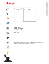
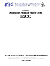
2.4 - DIMENSIONS
SPK 1000
11 41 12 13
31 32
42
18:28
giov 30 20ott 18
effettiva
richiesta
76
°C
84
°C
generatore
10/10
modulazione
100
%
INFO MENU
status
sanitaria
25
°C
H
E
D
W
A
H2
G
L1 L2 L3 L4 L5
Ø
Rbt T2
Rat T3
M T1T4
FRONT VIEW
UPPER VIEW
BACK VIEW
SPK
DIMENSIONS [mm]
Depth Width Height
Chim-
ney
conn-
ection
Furnace Focolare
L B L1 L2 L3 L4 L5 L6 L7 L8 W A H H1 H2 C D E Ø Ø f
1000 3760 2440 990 550 400 350 562 533 477 2310 1290 1240 1637 320 1545 376 952 1447 350 642

13
Technical features
ENGLISH
L6
B
L
C
L7
H1H1
L8
Ø f
Rbt T2
Rat T3
M T1T4
T5
T7
T8
SIDE VIEW SECTION
SIDE VIEW WITH CASING
SPK
CONNECTIONS Weight
T1 (M) T2 (R) T3 (R) T4 T5 (Sc) T6 T7 (S) T8 (Scond) G kG
PN6
inch [mm] [mm] [mm] inch
1000 DN 125 DN 125 DN 125 DN 65 R 1’’ 270 350 40 R 2’’ 2440

14
2.5 - OPERATING DATA AND GENERAL FEATURES
For the adjustment data: NOZZLES - PRESSURE - DIAGRAMS - FLOW RATES refer to the paragraph ADAPTATION TO OTHER
TYPES OF GAS.
SPK 1000
Boiler category I
2H
Modulation ratio 1:2
Rated heat output on P.C.I. Qn kW 940
Minimum heat output on P.C.I. Qmin kW 470
Rated useful power (Tr 60 / Tm 80 °C) Pn kW 923,2
Minimum useful power (Tr 60 / Tm 80 °C) Pn min kW 460,1
Rated useful power (Tr 30 / Tm 50 °C) Pcond kW 1006
Minimum useful power (Tr 30 / Tm 50 °C) Pcond min kW 508
Rated power performance (Tr 60 / Tm 80°C) % 98,2
Minimum power performance (Tr 60 / Tm 80°C) % 97,9
Rated power performance (Tr 30 / Tm 50°C) % 107
Minimum power performance (Tr 30 / Tm 50°C) % 108,1
Performance at 30% of the load (Tr 30°C) % 108
Combustion eciency at nominal load % 98,4
Combustion eciency with reduced load % 98,7
Casing heat loss with burner operating (Qmin) % 0,81
Casing heat loss with burner operating (Qn) % 0,19
Net ue gas temperature tf-ta (min)(*) °C 25,1
Net ue gas temperature tf-ta (max)(*) °C 31,0
Maximum permitted temperature °C 100
Maximum operating temperature °C 95
Flue gas mass ow rate (min) kg/h 790
Flue gas mass ow rate (max) kg/h 1581
Excess air % 29,54
Heat loss at chimney with burner on (min) % 1,29
Heat loss at chimney with burner on (max) % 1,60
Minimum heating circuit pressure bar 1
Maximum heating circuit pressure bar 6
Water content l 1413
Methane gas consumption G20 (pow.sup. 20 mbar) at Qn
m
3
/h 99,4
Methane gas consumption G20 (pow.sup. 20 mbar) at Qmin
m
3
/h 49,7
Massima pressione disponibile base camino Pa 100
Max condensate production kg/h 158
Emissions
CO at maximum heat output with 0% of O2
mg/kWh
2
NOx at maximum heat output with 0% of O2
mg/kWh
46
NOx weight with 3,5% of O2
mg/kWh
33
Electrical data
Power supply voltage/frequency V/Hz 230 / 50 - 400 / 50
Protection rating IP
-
Room Temperature = 20°C
(*) Temperature detected with appliance operation ow rate 80°C / ret. 60°C
CO
2
(min/max) See table ‘’NOZZLES - PRESSURE’’
Seasonal energy eciency to heat the room
2009/125 CEE (<=400Kw)
η
s
- see table ErP
Heat loss in stand-by ∆T 30°C - Pstb - see table ErP
Electricity consumption on standby - Psb - see table ErP

15
Technical features
ENGLISH
2.5.1 - TECHNICAL DATA ACCORDING ErP DIRECTIVE
SPK 1000
Element Symbol Unit
Eective nominal output
Pnominale
kW 923
Seasonal energy eciency to heat
the room
ƞ
s % 92
discharge
*
For CH only and combination boilers: useful heat output
Useful Heat Output in high-tempera-
ture regime
(Tr 60 °C / Tm 80 °C)
P
4 kW 923,2
Useful eciency at nom. heat output
in high-temperature regime
(Tr 60 °C / Tm 80 °C
ƞ
4 % 88,5
Useful heat output at 30% of nom.
heat output in low-temperature
regime (Tr 30 °C)
P
1 kW 304,6
Useful eciency at 30% of nom. heat
output in low-temperature regime
(Tr 30 °C)
ƞ
1 % 97,3
Range-rated boiler: YES / NO NO
Auxiliary electricity consumption
At full load elmax kW 2,120
At part load elmin kW 1,060
In stand-by mode P
SB kW 0,005
Other items
Heat loss in stand-by P
stb kW 2,15
Emissions of nitrogen oxides ref. PCS
NOx
Mg/kWh
40
Annual electricity consumption 6
Inside sound power level Q
HE GJ 2887
Livello di potenza sonora all’interno Lwa dB (A) -
For CH & DHW production boilers
Declarerd load prole -
Energy eciency in DHW production
mode
ƞ
wh % -
Daily electricity consumption Qelec kWh -
Daily fuel consumptionl Qfuel kWh -
Annual electricity consumption AEC kWh
Annual fuel consumption AFC GJ
in DHW production mode
-
*
Appliances not covered by Directive 2009/15 / EC

16
3
INSTALLATION INSTRUCTIONS
ATTENTION!
This boiler is intended solely for the use for
which it was expressly designed. Any other
use is to be considered improper and there-
fore dangerous.
This boiler heats water at a temperature
lower than the atmospheric pressure boiling
temperature.
Before connecting the boiler, have profes-
a) Thoroughly wash all the piping of the sys-
tem to remove any residues or impurities,
which could jeopardise proper operation
of the boiler.
b) Check that boiler is set up to operate with
the available type of fuel.
This can be seen written on the package
and on the technical feature plate;
c) Check that the chimney/flue has an
appropriate draught, without any bottle-
necks, and that no exhausts from other
has been
implemented to accommodate several
and regulations in force. Only after this
check
and chimney be mounted;
ATTENTION!
If there is dust and/or if there are
aggressive/corrosive vapours present in
the installation room, the appliance must
be protected suitably and must be able to
operate independently from the air in the
room.
ATTENTION!
Mount the appliance respecting the minimum
distances required for installation and main-
tenance.
The boiler must be connected to a central
heating system and/or domestic hot water
and output.
3.1 - GENERAL WARNINGS
3.2 - STANDARDS FOR INSTALLATION
It must be installed by a professionally qualied technician, who
shall take the responsibility of observing all local and/or
the applicable technical standards.
3.3 - PREVENTIVE VERIFICATION AND
VERIFICATION AND ADJUSTMENT
OPERATIONS
Before installing this appliance on old systems, check that:
- The chimney is suitable for appliances with condensation,
combustion products temperature, and built in compliance with
the standards in force in this regard.
Is as straight as possible, airtight and insulated, and has no
obstructions or constructions.
- The chimney is equipped with a tting to drain
condensate.
- The boiler room is equipped with a duct to drain condensate
produced from the boiler.
- The electrical system has been set up by a qualied techni-
cian in compliance with the rules in force.
- The rate, head and direction of the ow of the circulation
pumps are appropriate.
- The fuel adduction line and the tank, if any, are made ac-
cording to relevant standards in force.
- The expansion vessels can fully absorb dilation of the uid in
the system.
- The system has been cleaned from sludge and scaling.
NOTE!
For further details relating to the stand-
ards, rules and regulations for safe in-
stallation of the thermal unit, refer to the
section "Technical Information" on the
boiler page of the www.unicalag.it website
NOTE!
Further details in the section
‘‘Technical Information’’ on the boiler
page of the www.unicalag.it website

17
Technical features and dimensions
ENGLISH
SPK
L
width
(mm)
W
width
(mm)
H
height
(mm)
Net
Weight
(kg)
Weight
Packaging
(kg)
1000 4000 1500 1600
3.4 - PACKAGING
Check integrity of the content.
Keep the packaging material (plastic bags, etc.)
out of the reach of children as they are potential
sources of danger.
The manufacturer will not be held liable for damage
to persons, animals or objects due to failure to
comply with the above instruction.
As well as the appliance, the packaging contains:
Pouch with the following documentation:
- Manager operating instructions booklet HSCP
- Instruction booklet for the installer and maintenance engi-
neer
- BCM instructions booklet
- Certicate of conformity
- Testing certicate
- Gas conversion label
- Wieland socket for 230V - 50Hz power supply
Accessories box containing:
- 5 bends + a T + a plastic condensate draining cap
- External probe
- Storage tank probe
- Cables output sheet metal
- Condensate drain siphon pipe 1 m.
3.4.1 - HANDLING
The boiler must be handled by lifting it from the
holes on the upper plate or using a transpallet.
If it is possible to program replacements, you must provide
for intervention with protective washing equipped with basic
dispersant.
Washing must be carried out four weeks prior to replacement,
with the system operating at 35°C - 40°C
Attention! If the new boiler was replaced in an old system
without having provided for the aforementioned washing cy-
cle, do not start the system since any product residues in the
circuit can, after replacement, ll the generator with residues.
It is recommended to contact a specialised company for water
treatment.
- Only transport the boiler using appropriate
transport equipment
- Protect all parts against impacts if they are
to be transported.
- Follow the transport instructions on the
packaging.
OBLIGATION!
wear protective gloves
NOTE!
Further details in the section
‘‘Technical Information’’ on the boiler
page of the www.unicalag.it website

18
11 41 12 13
31 32
42
18:28
giov 30 20ott18
effettiva
richiesta
76°C 84°C
generatore
10/10
modulazione
100%
INFO MENU
status
sanitaria
25
°C
W
W
H
H
L
L9
SPK CLEARANCE mm
W L L9 H
1000 2000 3800 1000 1000
OPENING DOOR
ATTENTION
before opening the door, (right side) is
necessary:
- Close the gas cock on the pipe
power supply (burner upstream of the separa-
tion point between the power supply line and
the burner)
- Disconnect the Gas / Burner pipe
- Remove the 4 screws indicated and extract
the burner group (‘’ A ‘’ sledge)
- Remove the 6 front casing screws
(Upper lower and left side)
3.5 - POSITIONING IN BOILER
ROOM
The boiler must be installed in compliance with standards and
prescriptions in force.
The room must be well ventilated by openings with a total surface
no less than 1/30 the surface of the boiler room, with a minimum
of 0.5 m².
The ventilation openings must be permanent, communicate
directly with the outside and be positioned high or low according
to standards in force.
The location of the ventilation openings, the fuel supply circuits,
electric energy supply and lighting must comply with current legal
provisions in relation to the type of fuel used.
It is recommended to install the boiler as close to the chimney
connection as possible.
To make it easier to clean the smoke circuit, in front of the boiler,
there must be a free space no less than the length of the boiler
body and, in any case, never less than 1300 mm. Check that
with the door opened 90°, the distance between the door and
the adjacent wall is at least the length of the burner.
The boiler can be placed directly on the oor as it is equipped
with a base.
However it is useful to provide a at, level cement plinth capable
of bearing the weight of the boiler full of water.
When positioned on the plinth, the dimensions must be at least
B x A (see dimensions table).
When installation has been performed, the boiler must be perfectly
horizontal and stable (to reduce vibrations and noise).
Comply with the minimum overall dimension
distances in order to execute normal
maintenance and cleaning operations.

19
Technical features and dimensions
ENGLISH
3.5.1 - IMPORTANT NOTE
Before opening the hearth door, the following safety measures
must be taken:
- Cool the boiler by circulating the system water, and then
disconnect the burner from the electricity supply. Put a sign
on the boiler with the following text: DO NOT USE, BOILER
UNDER MAINTENANCE, OUT OF ORDER.
ATTENTION
be very hot; therefore pay the utmost caution.
REMOVING THE ANCHOR BRACKET
BURNER (transport protection)
ATTENTION
To remove the anchor bracket:
- follow the door opening phase
- using a suitable tool, remove the support

20
3.6 - FLUE GAS EXHAUST PIPE CONNECTION
To connect the ue gas exhaust pipe, local and national stand-
ards must be observed
In the event the boiler is replaced, ALWAYS replace the ue
gas pipe as well.
The boiler is type approved for the exhaust congurations listed
below:
ATTENTION:
HEAD AVAILABLE AT THE BASE OF THE CHIMNEY
D (Drain) I (Intake)
Dp = 100 Pa
-
The maximum permitted length of the pipes is determined
by head (Dp) available at the base of the chimney.
B23P
ATTENTION
For this type of connection, the room follows the
same installation rules for boilers with natural
draught.
Connection to a combustion products evacuation pipe outside
the room; the combustion air is taken directly from the room
where the appliance is installed.
NOTE!
Further details in the section
‘‘Technical Information’’ on the boiler
page of the www.unicalag.it website
/