Page is loading ...

Manitowoc Beverage Equipment
2100 Future Drive Sellersburg, IN 47172-1868
Tel: 812.246.7000, 800.367.4233 Fax: 812.246.9922
www.manitowocbeverage.com
Foodservice Group
In accordance with our policy of continuous product development and improvement,
this information is subject to change at any time without notice.
EI215710 Revision A (JMT/KAK) 15 January, 2000
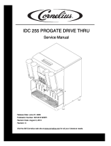
Harness Assembly
(P.N. 00809507)
d
One 24 VAC Lamp
(P.N. 00800810)
c
Multiplex Beverage Equipment Installation Instructions for
Out-of-CO2 Light Kit
P.N. 00215710
Power Supply Cord Assembly
(P.N. 00212282)
e
Four (4) Wire Nuts
(P.N. 00804102)
f

2
EI215710 Revision A (JMT/KAK) 15 January, 2000
Equipment Installation Instructions
Caution: To Avoid Serious Injury
Important: Read the following warnings before beginning an installation. Failure to do so
may result in possible death or serious injury.
DO Adhere to all National and Local Plumbing and Electrical Safety Codes.
DO Turn “off” incoming electrical service switches when servicing, installing, or
repairing equipment.
DO Check that all flare fittings on the carbonation tank(s) are tight. This check
should be performed with a wrench to ensure a quality seal.
DO Inspect pressure on Regulators before starting up equipment.
DO Protect eyes when working around refrigerants.
DO Use caution when handling metal surface edges of all equipment.
DO Handle CO
2 cylinders and gauges with care. Secure cylinders properly against
abrasion.
DO Store CO2 cylinder(s) in well ventilated areas.
DO NOT Throw or drop a CO2 cylinder. Secure the cylinder(s) in an upright position
with a chain.
DO NOT Connect the CO2 cylinder(s) directly to the product container. Doing so will
result in an explosion causing possible death or injury. Best to connect the
CO2 cylinder(s) to a regulator(s).
DO NOT Store CO2 cylinders in temperature above 125°F (51.7°C) near furnaces,
radiator or sources of heat.
DO NOT Release CO2 gas from old cylinder.
DO NOT Touch Refrigeration lines inside units, some may exceed temperatures of
200°F (93.3°C).
Notice: Water pipe connections and fixtures directly connected to a potable water supply
shall be sized, installed and maintained in accordance with Federal, State, and Local codes.

3
EI215710 Revision A (JMT/KAK) 15 January, 2000
Equipment Installation Instructions
Purpose of the out-of-CO2 light
To add an Out-of-CO2 Light to Multiplex Front Draw Dispens-
ing Tower.
Note: System must already have a low voltage wire pair in
the conduit and a low CO
2 pressure switch on the system unit.
Benefits of the out-of-CO2 light
Alerts serving crew when CO2 is about to deplete, prior to
drinks going flat.
Installing the multiplex out-of-CO2 light
1. Dispensing tower should have punched hole with cover
plug on front valve access door. If not present, a
1
/2" hole
will need to be drilled/punched on site.
2. Remove plug from Out-of-CO
2 Light hole in the dispensing
tower valve access door. Press light ( c ) into hole as far
as it will go, until locks in place.
3. Route harness assembly (d) through back access of dis-
pensing tower, through bottom of tower, and into base
cabinet. Connector ends route to CO
2 light, stripped ends
go to wire exiting conduit and power supply cord assem-
bly wire ( e ) as shown in schematic.
4. Press connectors onto light (c) terminals (not polarized).
Route wire harness and any excess wire to back access of
tower.
5. Pick one (1) of the transformer leads feeding dispensing
tower “ON/OFF” switch and unplug at the in-line white
molex 2-Pin connection.
CAUTION: Make sure tower transformer is disconnected/
unplugged from power source.
Connect the power supply cord assembly (e) to proper
mating connectors, in-line with the connectors, just sepa-
rated (see drawing).
6. Connect one (1) wire (wire nut [f]) from power supply
harness to one (1) wire from dispensing tower light har-
ness. Connect other wire (wire nut [f]) from power sup-
ply harness to one (1) wire from pressure switch (conduit
wire). Refer to schematic below.
7. Connect remaining wire (wire nut [f]) from the dispens-
ing tower light harness to remaining wire from pressure
switch (conduit wire). Refer to schematic below.
8. Re-connect transformer power. Short pressure switch ter-
minals and verify the Out-of-CO
2 Light on dispensing tower
turns “on”.
Pressure
Switch
Refrigeration Unit
Conduit
Dispensing Tower
e
d
f
c
/