Page is loading ...

700J-21-INST
3/21
Installation Manual
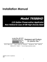
Model 700J
Moisture Sensor Kit for John Deere Large
Forage Harvester

2
DECLARATION OF INCORPORATION
MANUFACTURER: Harvest Tec Inc.
2821 Harvey St.
P.O. Box 63
Hudson, WI 54016, U.S.A.
REPRESENTATIVE ESTABLISHED IN COMMUNITY: Profitable Farming Company
Middle Barlington, Roborough
Winkleigh, Devon, EX19 8AG
ENGLAND
The person above certifies and declares that:
VIRTUAL MACHINE: Equipment mounted on a farm press and for the application of inoculants onto
forage crops.
MODEL: 700J-INST-20-Imp&Metric
BRAND: Harvest Tec
SERIAL NUMBER:
This application preservatives for hay Harvest Tec system meets the Directive 2006/42/EC of the
European Parliment and the Council of 17 May 2006 and other applicable European Directives
including Directive 2004/108/EC on the Electromagnetic compatability.
The application of preservatives for hay Harvest Tec system will be turned on after being installed on
a farm press has been declard in conformity with the Machinery Directive.
Person in the community authorized to provide information on the partly completed machinery and
making this statement:
Richard Snell, President, Profitable Farming Company
Signed on May 21, 2011: Middle Barlington, Roborough
Winkleigh, Devon, EX19 8AG
ENGLAND

3
Table of Contents
Introduction
Thank you for purchasing a Harvest Tec moisture monitor system. This moisture monitoring system has been
designed to be operated through a number of different displays and tablets using the Precision Baling App.
These include, the Harvest Tec display, the baler’s ISOBUS and display on the baler monitor, or iOS/Android
Tablet (not included).
The 700 Series Moisture System is designed to show moisture through the balers ISOBUS. Failure to follow
instructions can result in personal injury or equipment malfunction. If you need parts for the system, please
view the Parts Breakdown toward the back of this manual and contact your local authorized dealer to order the
parts.
System Requirements
The Baler must have Software Version 2.0.7 or higher
GreenStar 4th Generation Arm Command Display must have version 8.10.2393-23
*Made for Harvest Tec Display, Baler Integration, or Tablet*
For best performance ensure all displays are running the latest operating system
Tools Needed
Standard Wrench set
Side cutter
Hammer
Electric drill and bits
Standard Socket Set
Center Punch
PAGE
Introduction
3
System Requirements
3
Tools Needed
3
Installation of the Moisture Sensor Kit
4-6
Installation of Processor (IPM)
4
Main Wire Harness and Baler Interface Harness routing & Connections
4
Installation of Star Wheels – Non-UHD Baler
5
Installation of Star Wheels – UHD Baler
5
Installation of End of Bale Sensor
6
Tractor Setup
7
Display Options
8-9
Optional Tablet Display
8
Optional Baler VT Integration
9
Baler Display Integration
9
Baler Monitor Setup
10-13
Wiring Diagram
14
Pin Outs
15-17
Parts Breakdown
18-19
Star Wheel Sensors, Twine Diverters & Moisture Harness
18
Control Box & Wiring Harnesses
19
End of Bale Sensor Kit
19
Warranty
20

4
Installation of the Processor (IPM)
The locations shown are on the right twine box (looking form the back of
the baler). Mark and drill the two 3/8 (10mm) holes and install the (IPM)
with two 5/16 x 1 bolts, four 1/4” washers, and two 5/16” nylock nuts.
Main harness whip coming out of (IPM) should point to the ground.
When attaching other harness make sure to loop them below the (IPM)
so as not to funnel water into the control.
Main Wire Harness and Baler Interface Harness Routing and Connections
John Deere L330 / L340 Balers Harness Routing and ISOBUS Connection
Route cords 006-765B2 along this path. Keep cords
away from moving parts and hydraulic hoses. Secure
with existing cable clamps or use cable ties. When all
connections are made, secure wires as shown.
Locate harness 006-765VA and connect to baler interface harness
next to baler’s processor (below) on front left side of baler.
Remove baler terminating resistor and connect to short pigtail on
006-765VA Harness.
Route ISO Integration Harness (006-765VA) to
opposite side of baler through support cylinder
as shown in picture left.
Route harness from IPM and ICM as shown
in picture left, secure with cable ties.

5
Star Wheel Installation
Remove any material from the bale chute. The star wheels are to be mounted on the transition bracket on both
sides of the bale chute located after knotters shown above. Holes have been installed at the factory, however
you need to remove bracket and cut 3/4” (19mm) off the bracket as indicated below to allow proper spacing for
star wheel assembly.
Once complete, touch up with spray paint to prevent rusting and place the carriage bolts that mount the
transition bracket back in original bracket mounting holes (A) before mounting star wheel assembly (C). Insert
the 5/16” x 3” Allen head bolts (B) up through the transition bracket. Place the star wheel block over the nuts.
Place twine guard on top of star wheel (D).
Note: Star wheel with 6 position plug and twine diverter with extra holes needs to be mounted
on right side of baler.
Cut 3/4” Off Bracket
A
B
D
C

6
End of Bale Sensor Installation
The end of bale sensor determines the position of the needles on the baler. When the needle cycles the sensor
communicates this information to the 700 series that a bale has been made. Installation of this sensor is
required for use with the Harvest Tec job records. Reference “Sensor Settings” in Operation Manual.
End of bale sensor bracket (001-4648J) will be used.
Mount the end of bale sensor bracket (001-4648J) as shown. Under the twine box mark and drill two 3/8”
(10mm) holes and attach the bracket using two 5/16” x 1” self-tapping screws, and 5/16” flange nuts. Position
the bolts so the bolt heads are inside the twine box, so they do not interfere with the twine. Mount the sensor in
hole location centered alongside the needle arm, keep the sensor 1/4” (7mm) from the needle arm and tighten
both nuts. Route the sensor wire along the bottom side of the twine box toward the twine box pivot point.
Secure the wire to the twine box and around the pivot point to avoid damage to the wire. Once routed around
the pivot point, connect the EOB sensor wire to the main baler harness (006-765B2).

7
Tractor Setup
The general tractor setup of the 700 Series applicator can be seen above. The main harness of interest is the
tractor power/communication harness (006-765IC). This harness will connect at the tractor battery, to the ISO
Communication Module (ICM) mounted in the cab, a keyed power connection point, and connect at the hitch
area to the baler power/communication harness (006-765B2). View below to see highlighted installation
instruction:
12V Battery Connection
ISO Communication Module
Key Power Connection
Harness Connection to Baler
The 12V battery connection must be at the tractor battery. Connection to
alternative locations such as an accessory port can cause problems with
applicator system.
*MUST BE CONNECTED DIRECT TO TRACTOR BATTERY TERMINALS*
The ISO communication module is to be mounted inside the cab. Other
mounting locations can lead to issues with weathering and operation.
Once installed and the system is powered, a green light will turn on the
ICM module.
Ensure a solid keyed connection is found inside the cab and wired into.
Poor keyed power connection can result in applicator system issues.
The tractor harness connects at the hitch to baler power/communication
harness (006-765B2). This will allow the system components to
communicate with one another. Ensure connections are debris and
corrosion free.

8
Display Options
Optional Tablet Display
The iOS or Android Tablet displays offer the ability to communicate with the 700 series applicator system via
hard-wired connection to the ISO Communication Module (ICM). Through the free Precision Baling App, the
operator can set real time baling parameters to ensure the most precise application to every bale. This
provides a multi-use option while utilizing the improved app to select objects, enter data, and easily switch
through operational screens.
The Tablet Display offers easy integration by connecting a charging cable to the USB port on the ICM module
(USB port closest to LED light). Once, connected the Harvest Tec applicator will display upon opening the app
and powering up the applicator system. Tablets can be used in addition to integrated baler VT display.
*Made for iPad® (3rd generation minimum) or Android Tablet (Does not work with Amazon Fire).
Required to be running the most current operating system or one version previous.
*iPad is a trademark of Apple Inc., registered in the U.S. and other countries.
Optional Harvest Tec Display
Precision Baling App
The 700 series Harvest Tec Display will allow you to set your real time baling parameters to ensure the most
precise application to every bale. This is done by utilizing the improved touch technology to select objects,
enter data, and swipe through operational screens.
The Harvest Tec Display offers easy integration by connecting to the additional CAN plug on the 006-765IC
harness. Once, connected the Harvest Tec display will power up with applicator system.
Note: The Harvest Tec Display must be used as a standalone display, the baler cannot run both
integrated and on the Harvest Tec Display. Must be one or the other. Removal of the 006-765VA
integration harness is required when equipped.

9
Optional Baler VT Integration
Baler Display Integration
The ISOBUS Monitor utilizes a combination of soft keys, touch panel, and number menus. All buttons are
labeled and color coded.
The 700 series integration to the Baler VT allows for the ability to set your real time baling though the baler
VT and monitor both baler settings and Harvest Tec system parameters through one monitor to ensure the
most precise application to every bale.
The 700 series offers easy integration by connecting to the additional CAN plug on the 006-765B harness.
Once connected the Harvest Tec system will display with power up of the baler and applicator system.

10
Baler Monitor Setup
Follow the instructions below to finish setup of the Harvest Tec 700J system through the John Deere ISOBUS
monitors.
2600 Series Monitors
1. Starting from the Home Page select the Up Arrow with the dot on top.
2. On the Machine Setup page that will appear, select soft key D (Page Right)
3. On the next page select the Harvest Tec option. The Check mark indicates that the system is now on.

11
Baler Monitor Setup (continued)
2600 Series Monitor Baler run Screen Details
Harvest Tec information will display on the bottom of screen in the center
Stats Icon Descriptions
Applicator is not in a run mode.
System is at End of Row as indicated by the
Optional Hay Indicators (Crop-Eyes).
Applicator is in Automatic or Manual Mode.
System is in Pause Mode from pressing the
Pause button.
Current moisture
Tagger On
Applicator Status Icon
Target Preservative Rate
Actual Preservative Rate
Measurement being used
for application
Last bale moisture

12
Baler Monitor Setup
GreenStar 4th Generation Arm Command Display
Display software version 8.10.2393-23 or later, is required on the display to ensure compatibility. Earlier
versions are not all compatible. This information can be found by selecting “Menu” in the lower right-hand
corner of the display, select the third tab down labeled “System”, press “Software Manager”, then the “Version
Information” tab and the software versions will be displayed (Figure 1).
Once you have made sure the software version is at or above the recommended version, return to the tractor
run screen. When on the run screen, there will be an ISO button (Figure 2) on the bottom toolbar. Pressing this
will bring you into the “Connected ISOBUS Implements” page (Figure 3). If Harvest Tec is powered up correctly
and active on the ISOBUS, the icon labeled “Forage, Harvest Tec, Inc.” will display. If the files are still loading
you will see a loading status.
Once the files are loaded onto the display, you will receive a warning (Figure 5) to inform the operator that
another device has been added onto the ISOBUS. This can be accepted and then selecting the Harvest Tec
device in the ISOBUS menu will bring up the Harvest Tec system.
Figure 1
Figure 2
Figure 3
Figure 4
Figure 5

13
Baler Monitor Setup (continued)
When the Harvest Tec system is connected you can also access the applicator by following these screens:

14
Wiring Diagram – 700 Series Moisture Only
1. Connect the power harness (006-765IC) to the tractor battery (12 volt) using the red wire with fuse to the positive side
and the black wire to the negative.
A. The power harness must be connected to the battery!
CONTACT HARVEST TEC BEFORE MODIFICATIONS.
*The unit will draw more amps than convenience outlets can handle. Any modifications of the power
harness will void systems warranty*
B. This unit will not function on positive ground tractors.
C. If the unit loses power while operating it will not keep track of accumulated pounds of product used.
2. The power harness on the tractor (006-765IC) will run from the tractor battery to the hitch. The power harness on the
baler (006-765B2) will connect to the tractor power harness (006-765IC) at the hitch.
3. Connect the keyed power wire (006-765CPH) to a keyed power source on the tractor.
The keyed power wire must connect to a keyed source or the unit will not power up correctly.
4. Attached the ISO Communication Module (006-6673) to the tractor power harness (006-765IC).
5. Attach the End of Bale (EOB) connection on baler harness (006-765B2) to the EOB Sensor (006-7401).
6. Attach star wheel (030-4642 U/UE) connection to ISO Pump Module on pump plate assembly.
System Wiring Diagram
Star Wheels
030-4642 (U/UE)
ISO Communication Module
(ICM) 030-6673
Power Harness on Tractor
006-765IC
700 ISO Pump Module
006-7671LS
Power Harness on Tractor
006-765B2
End of Bale Sensor
006-7401
Moisture Harness
006-7303EM2
Key Power Harness
006-765CPH
Optional Harvest Tec
Display Harness
006-765GH
Baler Integration Harness
006-765VA
Active Terminator from Baler

15
Pin Outs
Integrated Control Module (ICM) on harness 006-765IC
(Deutsch Plug Number: DTM06-12SA)
ISOBUS Plug on harness 006-765IC
(Deutsch Plug Number: DT04-4P)
Power / Communication Harness 006-765IC at Baler Hitch
(Deutsch Plug Number: HDP24-24-18PN)
Pin 1
Red
+12V from ECU
Pin 2
Purple
Signal Wire
Pin 3
Red/White
+12V CAN X
Pin 4
Black/White
Ground CAN X
Pin 5
Orange
CAN X Hi
Pin 6
Blue
CAN X Lo
Pin 7
Green
ISO CAN Lo
Pin 8
Yellow
ISO CAN Hi
Pin 9
White
GPS Expansion 1
Pin 10
Gray
GPS Expansion 2
Pin 11
Brown
GPS Expansion 3
Pin 12
Black
Ground from ECU
Pin 1
Red
+12V from ECU
Pin 2
Yellow
ISO CAN Hi
Pin 3
Green
ISO CAN Lo
Pin 4
Black
Ground from ECU
Pin 1
Not Used
----
Pin 2
Yellow
ISO CAN Hi
Pin 3
Green
ISO CAN Lo
Pin 4
Red
+12V Power to ECU
Pin 5
Black
Ground to ECU
Pin 6
Red
+12V From Battery
Pin 7
Not Used
----
Pin 8
Black
Ground From Battery
Pin 9
Not Used
----
Pin 10
Purple
Signal Wire
Pin 11
Red/White
+12V CAN X
Pin 12
Black/White
Ground CAN X
Pin 13
Orange
CAN X Hi
Pin 14
Blue
CAN X Lo
Pin 15
White
GPS Expansion 1
Pin 16
Gray
GPS Expansion 2
Pin 17
Brown
GPS Expansion 3
Pin 18
Not Used
----
1
v
3
v
2
v
4
v
7
8
9
10
11
12
1
2
3
4
5
6

16
Pin Outs (continued)
Power / Communication Harness 006-765B2 at Baler Hitch IPM
(Deutsch Plug Number: HDP26-24-18SN)
Power / Communication Harness 006-765B2 at IPM Module
(Deutsch Plug Number: HDP24-24-18SN)
*IPM Module Whip Plug- Pin # 5 Not Used
Solenoid 1 Plug on Baler Harness 006-765B
(Deutsch Plug Number: APTIV 12052641)
Solenoid 2 Plug on Baler Harness 006-765B
(Deutsch Plug Number: APTIV 12052641)
Pin 1
Not Used
----
Pin 2
Yellow
ISO CAN Hi
Pin 3
Green
ISO CAN Lo
Pin 4
Red
+12V Power to ECU
Pin 5
Black
Ground to ECU
Pin 6
Red
+12V From Battery
Pin 7
Not Used
----
Pin 8
Black
Ground From Battery
Pin 9
Not Used
----
Pin 10
Orange/White
+12V Power to EOR
Pin 11
Not Used
----
Pin 12
Not Used
----
Pin 13
Not Used
----
Pin 14
Not Used
----
Pin 15
Not Used
----
Pin 16
Not Used
----
Pin 17
Not Used
----
Pin 18
Not Used
----
Pin 1
Not Used
----
Pin 2
Yellow
ISO CAN Hi
Pin 3
Green
ISO CAN Lo
Pin 4
Red
+12V Power to ECU
Pin 5
Black
Ground to ECU
Pin 6
Red
+12V From Battery
Pin 7
Not Used
----
Pin 8
Black
Ground From Battery
Pin 9
Not Used
----
Pin 10
Orange/White
+12V Power to EOR
Pin 11
Orange/Black
Ground to EOR
Pin 12
Purple/Green
EOR Signal
Pin 13
Blue/White
EOB Signal
Pin 14
Gray/Red
+12V Power to Solenoid 1
Pin 15
White/Black
Ground to Solenoid 1
Pin 16
Orange/Red
+12V Power to Solenoid 2
Pin 17
White/Black
Ground to Solenoid 2
Pin 18
Not Used
----
Pin B
Gray/Red
+12V to Solenoid 1
Pin A
White/Black
Ground to Solenoid 1
Pin B
Orange/Red
+12V to Solenoid 2
Pin A
White/Black
Ground to Solenoid 2
A
B

17
Pin Outs (continued)
CAN / IDM on Baler Harness 006-765B
(Deutsch Plug Number: DT06-4S)
End of Bale Sensor Plug on Baler Harness 006-765B
(Deutsch Plug Number: DT06-3S)
End of Row Sensors Plug on Baler Harness 006-765B
(Deutsch Plug Number: DT06-3S)
Integration Harness Plug on Baler Harness 006-765VA
(Plug: APTIV 12052848)
Pin A Not Used ----
Pin B Red TBC Power
Pin C Not Used ----
Pin D Gray TBC Ground
Pin E Orange CAN Hi
Pin F Blue CAN Lo
Pump Connection on 700 Controller Harness
(16 AWG Two-Wire Plug)
Pin 1 Red Power to Pump
Pin 2 Black Ground to Pump
Pin 1
Red
+12V to ECU
Pin 2
Yellow
ISO CAN Hi
Pin 3
Green
ISO CAN Lo
Pin 4
Black
Ground to ECU
Pin 1
Orange/White
+12V to End of Bale Sensors
Pin 2
Orange/Black
Ground to End of Bale Sensors
Pin 3
Blue/White
Signal
Pin 1
Orange/White
+12V to End of Bale Sensors
Pin 2
Orange/Black
Ground to End of Bale Sensors
Pin 3
Blue/White
Signal
1
3
2
4
1
3
2
Pin 2
Pin 1
D
F
A
F

18
Star Wheel Sensors
Moisture Harness
Ref
Description
Part#
Qty
1
Block Cover
006-4642UC
1
2
Star Wheel Block
006-4642UB
1
3
Star Wheel Gasket
006-4642UG
1
4
Electric Swivel
006-4642A
1
5
Swivel Insert
006-4642B
1
6
Encoder
006-4512E
1
7
Encoder Mount
006-4512P
1
8
Washers
006-4642K
1
9
Star Wheel
006-4642US
1
10
Encoder Harness (6 pin)
006-7307EM
1
NP
Moisture Harness (2 pin)
006-7307M
1
1-10
Star wheel assembly
(w/ Encoder)
030-4642UE
1
1-5
8,9,NP
Star wheel assembly
(w/o Encoder)
030-4642U
1
Ref
Description
Part #
Qty
11
Moisture Harness
006-7307EM2
1
11
2
1
9
3
8
2
6
4
2
5
7
10

19
Control Box and Wiring Harnesses
Ref
Description
Part#
Qty
Ref
Description
Part#
Qty
1
Power Lead Baler 20’
006-765B2
1
NP
Baler Integration Harness
006-765VA
1
2
Power lead tractor
006-765IC
1
NP
Dust Plug Kit
006-765DP
1
3
Key Switch Wire
006-765CPH
1
4
ISO Pump Module
006-7671LS
1
5
ISO Communication
Module
006-6673
1
End of Bale Sensor Kit
Ref
Description
Part #
Qty
1
End of Bale Sensor
006-7401
1
2
End of Bale Ext.
006-7401EXT
1
Complete Assembly
EOB-LS-STD
2
1
4
2
5
3
1
2

20
Harvest Tec Inc. Warranty and Liability Agreement
Harvest Tec, Inc. will repair or replace components that are found to be defective within 12 months from the
date of manufacture. Under no circumstances does this warranty cover any components which in the opinion
of Harvest Tec, Inc. have been subjected to negligent use, misuse, alteration, accident, or if repairs have been
made with parts other than those manufactured and obtainable from Harvest Tec, Inc.
Our obligation under this warranty is limited to repairing or replacing free of charge to the original purchaser
any part that in our judgment shows evidence of defective or improper workmanship, provided the part is
returned to Harvest Tec, Inc. within 30 days of the failure. If it is determined that a non-Harvest Tec branded
hay preservative has been used inside the Harvest Tec applicator system where the failure occurred, then
Harvest Tec reserves the right to deny the warranty request at their discretion. Parts must be returned through
the selling dealer and distributor, transportation charges prepaid.
This warranty shall not be interpreted to render Harvest Tec, Inc. liable for injury or damages of any kind,
direct, consequential, or contingent, to persons or property. Furthermore, this warranty does not extend to loss
of crop, losses caused by delays or any expense prospective profits or for any other reason. Harvest Tec, Inc.
shall not be liable for any recovery greater in amount than the cost or repair of defects in workmanship.
There are no warranties, either expressed or implied, of merchantability or fitness for particular purpose
intended or fitness for any other reason.
This warranty cannot guarantee that existing conditions beyond the control of Harvest Tec, Inc. will not affect
our ability to obtain materials or manufacture necessary replacement parts.
Harvest Tec, Inc. reserves the right to make design changes, improve design, or change specifications, at any
time without any contingent obligation to purchasers of machines and parts previously sold.
Revised 4/17
HARVEST TEC, INC.
P.O. BOX 63
2821 HARVEY STREET
HUDSON, WI 54016
PHONE: 715-386-9100
1-800-635-7468
FAX: 715-3 81-1792
/