3030 Corporate Grove Dr.
Hudsonville, MI 49426
Phone: 616.396.1355
itc-us.com
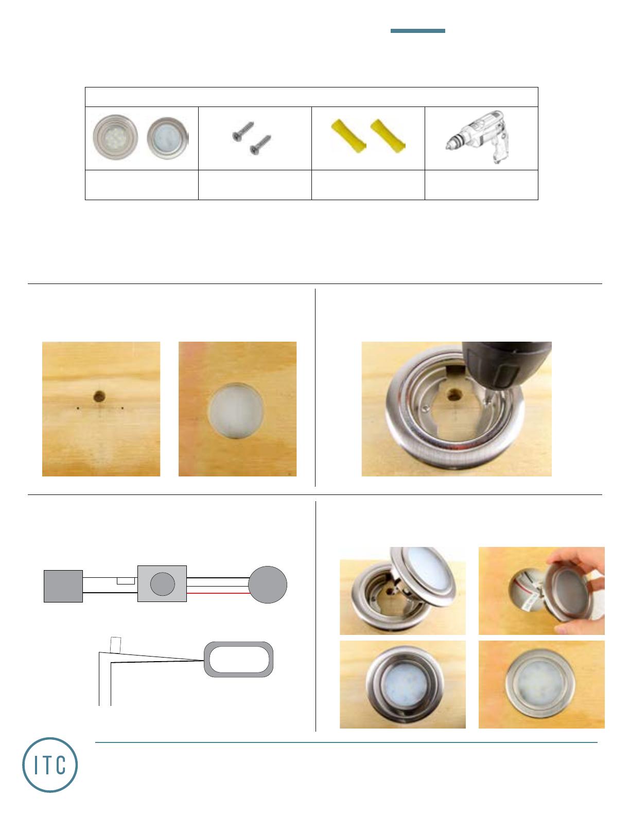
1. 69554 | Determine the installation location and use
the bezel to mark the location of the screw holes
and wiring hole. 69553 | cut out 2.25” hole for light.
3. 69554 & 69553 |Using the wiring diagrams below,
wire the light to a three way switch and your incom-
ing 12V DC power.
Test the light.
Red (+)
White (+)
Black (-)
White (+)
Black (-)
12V DC
Supply
Circuit
LED Light
2. 69554 | Drill a hole and pull the units wiring through.
Screw down the bezel using the provided screws.
4. 69554 |Feed the wires back through the hole and
push the light into the bezel. 69553 |Push light into
hole.
Fuse
IMPORTANT SAFETY INSTRUCTIONS. READ CAREFULLY FOR YOUR PROTECTION AND SAVE ALL
INSTRUCTIONS.
*Disconnect power before installing, adding or changing any component.
*To avoid a hazard to children, account for all parts and destroy all packing materials.
* It is recommended that fuse protection be added to the positive(+) input.
Surface Recessed
69554 69553
PARTS/TOOLS NEEDED:
Decor Overhead Light Mounting Screws
(Qty: 2)
Butt Splice Connectors
(Not Provided)
Power Drill & 2.25” Hole
Saw
Double Pole Dimming Switch
(not provided)
INSTALLATION INSTRUCTIONS
Decor Overhead Light
Part#: 69553 & 69554
For warranty information please visit www.itc-us.com/warranty-return-policy
DOC #: 710-00105 • Rev A • 06/08/2023
Page 1 of 1
+12V
Red (+)
Black (-)
Incoming
12V DC
Power
Fuse

