7
1-800-727-5477 • www.sargentlock.com
7800 and 8200 Series Mortise Lock
Installation Instructions
Used with Sectional Trim and V Series Indicators
Copyright © 2019, 2020, 2021, 2022, SARGENT Manufacturing Company. All rights reserved. Reproduction in
whole or in part without the express written permission ofSARGENT Manufacturing Company is prohibited. Patent
pending and/or patent www.assaabloydss.com/patents.
A8257E 4/22
6
1
2
3
4
5
6
6
7
4A
4B
4C
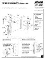
Figure14
Indicator Parts List
6
Figure14 Description Part Number Req.
1
Sectional Escutcheon - Cylinder 81-0742 x finish
1
Sectional Escutcheon - Coin Turn 82-5635 x finish
Sectional Escutcheon - Thumbturn (Standard) 82-5630 x finish
Sectional Escutcheon - Thumbturn (LB Option) 82-5631 x finish
Sectional Escutcheon - Thumbturn (T1) 82-5632 x finish
Sectional Escutcheon - Thumbturn (T2) 82-5633 x finish
Sectional Escutcheon - Thumbturn (T3) 82-5634 x finish
Sectional Escutcheon - No Input/Blank 81-0742 x finish
2 Indicator Window 81-0811 1
3
Indicator Display Assembly - Green Unlocked / Red Locked 82-5602
1
Indicator Display Assembly - Green Vacant / Red Occupied 82-5603
Indicator Display Assembly - Green Unlocked Icon / Red Locked Icon 82-5604
Indicator Display Assembly - White Unlocked / Red Locked 82-5605
Indicator Display Assembly - White Vacant / Red Occupied 82-5606
Indicator Display Assembly - White Unlocked Icon / Red Locked Icon 82-5607
Indicator Display Assembly - Green Ouvert / Red Fermé 82-5684
Indicator Display Assembly - Green Libre / Red Occupée 82-5685
4A Indicator Spindle Cam - Thumbturn/Coin Turn 81-0745
14B Indicator Spindle Cam - Cylinder/No Input / Blank 81-0756*
4C Indicator Spindle Cam - 05, 37, 38, 59 Function 82-5577*
4D Indicator Spindle Cam - 05 (Inside) 82-5673 1
5 Indicator Retaining Pad 81-0749 1
6 Sectional Indicator Screw Pack 82-5590 x finish 1
7 Sectional Indicator Mounting Plate 81-0750 1
8 Sectional Indicator Template Kit (not shown) 82-5601 1
* These parts are for 1-3/4" standard thickness doors. For other thicknesses, please contact factory.
Note:
Reference 8200 Series parts manual for all lock body parts.
4D