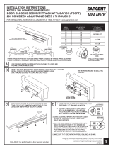
3 Final Adjustment and Regulating Procedures
Adjust Spring Power According to Chart
(Figure 5)
Turn spring adjustment nut clockwise the
required number of turns to match door
width as indicated in chart.
NOTE:
• Where strong drafts exist, increase
spring power as needed.
• 351 Style door closers normally leave
the factory with spring adjustment
set at eight (8) turns.
Adjustment Instructions (Figure 6)
Minimum recommended door closing
time is 6 seconds for doors opened to
90 degrees.
Using 1/8" hex wrench, turn valve screw
clockwise to slow down or counter
clockwise to speed up door movement.
Turn backcheck valve clockwise to increase
intensity of backcheck action or counter
clockwise to decrease checking (as
desired).
CAUTION: Set backcheck valve for a slight
cushioning effect. It is damaging to the
closer if the checking action is too abrupt.
Backcheck should never be used as a
door stop. Always use a door stop to stop
the door.
Install Cover (Figure 7)
1. Assemble three (3) short cover
screws (#8-32 x 5/16") into bottom of
closer body cover mounting bracket
approximately one (1) turn.
2. Slide cover onto backplate and closer
assembly. Secure with three (3) cover
screws.
CAUTION: Avoid interference with
electronics and wires during installation
of cover.
Maximum
Width of
Door Interior
Only
Clockwise
Turns of
Adjusting
Nut
2' 8" 8
3' 0" 8
3' 6" 12
4' 0" 16
Max adjustment is approx 20
turns. Do not forcibly extend
adjustment beyond limits.
5/8" Spring
Adjustment Nut
#8-32 x 5/16"
Cover Screw
Figure 5
Figure 6
Figure 7
Hex Wrench
Backcheck
Valve
Door Closing
Speed Valve
Latching
Speed Valve
Delayed
Action
Backcheck
Latch
Sweep
4
A7396E 09/21
Copyright © 2005, 2008, 2011, 2021, SARGENT Manufacturing Company. All rights reserved. Reproduction in
whole or in part without the express written permission ofSARGENT Manufacturing Company is prohibited.
1-800-727-5477 • www.sargentlock.com
2900 FIREGUARD® Electromechanical Closer-Holder
Installation Instructions
2980 Hold-Open Swing Free Arm/Pull (Hinge) Side Mounting