1-800-727-5477 • www.sargentlock.com A7411C 8/22
Copyright © 2009, 2022 SARGENT Manufacturing Company. All rights reserved. Reproduction in
whole or in part without the express written permission of SARGENT Manufacturing Company is
prohibited.
WARNING
This product can expose you to lead
which is known to the state of California
to cause cancer and birth defects or other
reproductive harm. For more information go
to www.P65warnings.ca.gov.
607 Locking Slide
607-1 Locking Slide Replacement Kit
(For all 713 ET Trims)
On Lockable ET Controls:
Installation Instructions
Replacement Kit
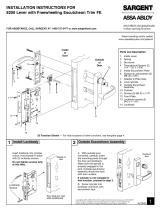
When reassembling the slide support, ensure
the slide support is beside the return spring,
not on it.
VIEW “X”
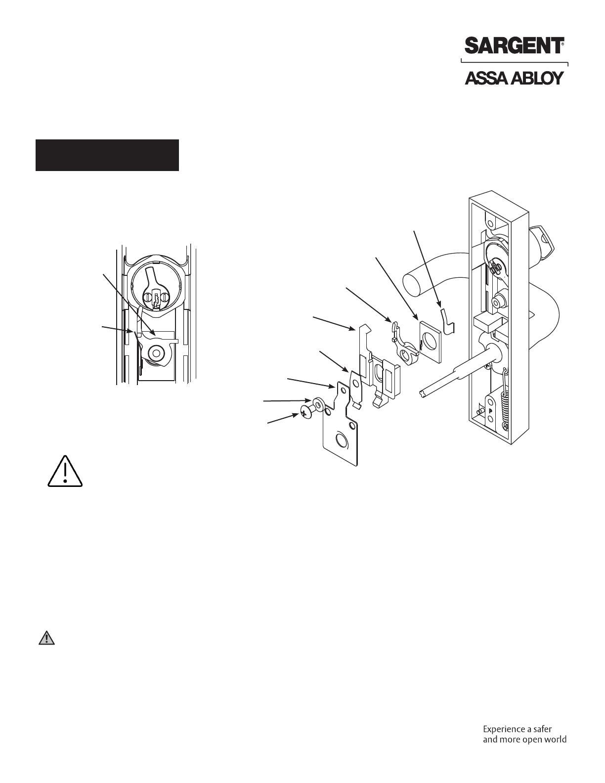
1. Remove the truss head screw, fusible link, locking slide spring, retaining plate and locking slide.
2. Place the new locking slide over the slide support and return spring making sure that the slide
support is beside the return spring.
Note: See View “X” for proper installation of slide support, spring support, and return spring.
3. Align the locking slide spring, retaining plate, fusible link, and truss head screw.
4. Tighten securely.
VIEW “X”
Slide
Support
Return
Spring
Return Spring
Spring Support
Locking Slide
Locking Slide Spring
Retaining Plate
Fusible Link
Truss Head Screw
Slide Support