Page is loading ...

Blade 2
Building instructions - Blade 2 Page 1
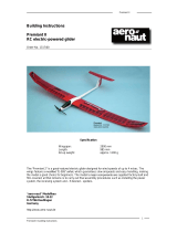
BLADE 2
Electric ducted fan model
Order No. 1356/00
Specification
Wingspan 1404 mm
Length 1022 mm
Wing area 35.6 dm²
Wing loading 73 – 106 g
All-up weight 2600 - 3800 g
RC functions
Aileron, elevator and rudder
Motor
“aero-naut” Modellbau GmbH & Co. KG
Stuttgarterstr. 18-22
D-72766 Reutlingen
http://www.aero-naut.de
© “aero-naut” Modellbau

Blade 2
Building instructions - Blade 2 Page 2
Power system
90 mm Ø CFRP ducted fan units
Recommended motors: Battery to suit motor
Fun 500-19 16 sub-C cells
HP 220/20 A3P6 16 sub-C cells
HP 220/30 A4SP4 18 - 22 sub-C cells
LMT 1930-12 16 sub-C cells
LMT 1930-16 22 sub-C cells
We strongly recommend the use of epoxy laminating resin for all glued joints as it penetrates into the
narrowest of gaps, ensuring that joints are really strong. For some processes the resin should be
thickened with a thixotropic agent. Use coarse abrasive paper to roughen all areas of the fuselage
which are to be glued; the white surface of the pigmented parts must be sanded off completely to
ensure good adhesion. It is essential to use slow-setting epoxy for all joints involving the GRP
components; do not trust 5-minute epoxy.
Experienced builders may wish to deviate from the sequence of construction described in these
building instructions; this is left up to the discretion of the modeller.
Air intake rings
The intake rings (6) should be glued to the inside of
the motor pods. Apply epoxy only to the outer, round
edge; it is best to apply release agent to the inner
rounded face of the intake rings before applying the
glue, as any excess resin can then be filed off easily,
producing a smooth surface on the inner face of the
intake rings (6).
Glue the ducted fan units in the recess of the intake
rings (6), working from the inside of the motor pods,
then install the motors and connect the cables.
Cut out the nozzle (14) from the film supplied, and stick it to the mantle ring of the ducted fan unit from
the rear using adhesive tape.
Seal the underside of the motor pods by attaching the pod hatches (13) with adhesive tape.

Blade 2
Building instructions - Blade 2 Page 3
Fins
The vertical fins (15) can now be glued to the motor pods. Note that the tips should be canted inward:
they should be about 22 cm apart.
Launch mechanism
Bend the launch hook to shape from the steel rod (16) to accept the tow-ring (17). Drill a hole for the
hook in the underside of the fuselage on the centreline, 2 cm behind the fuselage separation line. Glue
the hook securely in the hole.
Cut an opening in the fuselage (1) at a point 17 cm forward of the tail end of the fuselage. The opening
must be large enough to accept one finger, but with generous clearance to ensure that your finger
does not get stuck when the model is launched. Glue a piece of wood on the inside of the finger hole,
facing the tail, and round it off carefully so that your finger does not press against a sharp edge when
the rubber catapult is stretched.
Canopy
Glue the steel pin (3) in the fuselage (1) at the front
edge of the recess for the canopy (2); it should be
angled forward as shown. Glue the brass tube (4) to
the front of the canopy (2) as follows: slip the tube
(4) on the steel pin (3), apply a little epoxy to the
tube and press the canopy (2) down onto it. Leave
the epoxy to set hard, then remove the canopy and
apply more epoxy round the joint. Open up the front
face of the auxiliary air intake in the top of the
canopy (2).
The RC system receiver, speed controller and
receiver battery are stowed under the removable
canopy. The canopy is first fitted onto the steel rod
in the fuselage, then secured by means of two self-
tapping screws through the canopy flange and into
the fuselage, about 20 cm from the front on both sides. Glue scrap pieces of plywood over the inside
of the holes to provide additional support for the screws. A length of steel wire is installed in the
fuselage forward of the spar which can be used as the aerial. However, please read the instructions
regarding aerials supplied by your RC system manufac-turer, and carry out a range check before flying
the model.
The speed controller should be located under the canopy (2) in line with the auxiliary air intake, so that
it is cooled by the airflow through it. Cut a hole through the fuselage forward of the speed controller
through which the cables can be routed.
Opening on the
underside

Blade 2
Building instructions - Blade 2 Page 4
Fuselage nose cone
Fit the nose cone (5) on the fuselage (1) from the front, and secure it with four self-tapping screws.
Elevons
The servos (Graupner DS 368 or comparable) for the elevons are installed in the wing panels. Solder
the servo leads to the cables already fitted in the fuselage, following the RC system instructions, and
fit suppressors in the leads.
Cut the slots for the horns (12) in the elevons, and glue the horns (12) in the slots. Connect the horns
(12) to the servos using the threaded pushrods (11) and clevises (10). Fit the servo well covers (7) and
tape them in place.
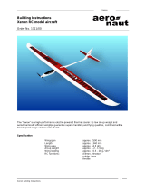
Elevon travels
When an aileron command is applied: 6 mm up, 6 mm down.
When an elevator command is applied: 10 mm up, 10 mm down.
The elevon travels are programmed using the servo travel adjustment facility on your transmitter.
Aileron 6 mm
Elevator 6 mm
Aileron 6 mm
Elevator 6 mm

Blade 2
Building instructions - Blade 2 Page 5
Battery supports + Centre of Gravity
To set the correct Centre of Gravity install all the internal components including motors, cables, con-
nectors and RC system, fit the formers (8 + 9) and the two flight batteries (but don’t glue them!), and
adjust the position of the flight packs until the model balances at the stated point. The correct CG is 36
cm forward of the rearmost edge of the fuselage. Place the model on a length of tube located at this
point, and check that the CG really is correct.
Solder the four sockets (18) to the cables attached to the two speed controllers, and glue the sockets
(18) in the former (8). The four plugs can now be soldered directly to the NC batteries, using the
sockets installed in former (8) as a template. Cut a slot in the fuselage (1) under the canopy to accept
the former (8), to keep it accurately in position when it is glued in place. Please take great care to
connect the batteries with correct polarity. Sand off the burned edges from the joint areas of the
formers before gluing them in the fuselage.

Blade 2
Building instructions - Blade 2 Page 6
Parts List No. off
1. Fuselage and wing 1 GRP
2. Canopy 1 GRP
3. Steel pin 1 Metal, 2 x 50 mm
4. Brass tube 1 Brass, 2 / 3 Ø x 30 mm
5. Fuselage nose cone 1 GRP
6. Air intake ring 2 GRP
7. Servo well cover 2 GRP
8. Former 1 Birch ply, 2.5 mm
9. Former 1 Birch ply, 2.5 mm
10. Clevis 2 Metal, 7489/01
11. Threaded pushrod 2 Metal, 7488/04
12. Elevon horn 2 GRP
13. Pod hatch 2 GRP
14. Nozzle 2 Film
15. Fin 2 GRP
16. Launch hook 1 Steel rod 3 x 60 mm
17. Tow-ring 1 Metal, 7801/05
18. Socket 4 4 mm Ø, ready made, 7456/24
19. Plug 4 4 mm Ø, ready made, 7456/24
20. Self-tapping screw 6 2.2 x 13 mm, 7768/00
21. Decal sheet 1 Self-adhesive film
22. Illustrated building instructions 1
Operating instructions - Blade 2
Installing the receiving system.
The Blade 2 requires only two control functions: elevons (superimposed ailerons / elevators) and
speed controller. The elevon travels must be correct if the model is to fly to its full potential.
On no account set excessive elevon travels initially, as this would make the model “twitchy” around the
lateral axis.
Test-flying
Ducted-fan models are no more difficult to fly than models with conventional propellers. Internally
mounted power plants offer certain important advantages: in contrast to a propeller, the impeller
generates virtually no unwanted torque effects, has practically no influence on the model’s movement
around the roll axis, and produces no turbulent airflow in the region around the fuselage. The
drawback is that there is no forced airflow over the elevons at launch time. This simply means that the
model should not be hand-launched.

Blade 2
Building instructions - Blade 2 Page 7
The safest method of launching is to use a catapult. A simple, proven catapult can be made from a
length of rubber cord as sold by model shops for bungee systems. This gives the Blade 2 the essential
initial acceleration. All you need is 7 to 10 metres of rubber cord of at least 8 mm
2
cross-section. If the
rubber is thinner, use multiple strands. The rubber should then be extended by attaching about 10 to
15 metres of nylon cord (e.g. thin washing line) to it. Tie the tow-ring to the end of the nylon line.
Anchor the rubber cord to the ground by means of a stout tent peg. Connect the tow-ring to the launch
hook on the model.
Check all functions carefully before flying the model. Set slight up-elevator trim for the first flight. To
launch the model the rubber should be stretched to 2.5 - 3 times its slack length. Hold the Blade 2 by
the tail end of the fuselage using one finger.
After release the Blade 2 should be airborne after just a few metres, and will make the transition into a
straight climb, the climb angle dependent primarily on the thrust of the power system. This all assumes
that the Centre of Gravity is set correctly - it is no bad idea to move it forward by a few millimetres for
the first flight - and the trims are also correct. We strongly advise you to keep the model’s climb angle
quite shallow at first so that adequate speed can build up, as it is a characteristic of ducted fans that
they are only capable of working efficiently when the model is flying fast. If trim corrections are
required, wait until the model is flying straight and level, or flying a broad turn at a safe height, before
you make any changes.
Ducted fan powered jets generally only reach their full top speed when flown straight and level, or
when first dived after a climb to height. Once the model is flying fast, the high speed can and should
be maintained quite easily. The secret of smooth, scale-like jet flying is a fluid, wide-ranging piloting
style, i.e. avoid slowing the machine unnecessarily. This makes for efficient flying, and therefore
extended flight times.
Naturally the Blade 2 is also capable of simple aerobatics such as rolls and loops. If the model’s fan
system is not particularly powerful you should ensure that the model has plenty of airspeed at the start
of manoeuvres.
For landing we recommend approaching at a fairly high speed. For the first flight it can do no harm to
keep sufficient capacity in the flight packs for an overshoot and second approach. But please bear in
mind that a ducted fan power system’s ability to accelerate is not exactly exhilarating at low airspeed
(i.e. just before touch-down).
And do take care: after touch-down it is important to check that there are no foreign bodies in the air
intakes before you switch the motors on again!
All of us at “aero-naut” Modellbau hope you have loads of fun with this very beautiful model.
/