Page is loading ...

Phone: (844) LEDONE6 | Fax: 1-510-217-9461 | Web: www.ledonecorp.com
`
LOC-WP Multi Watt Series Installation Guide
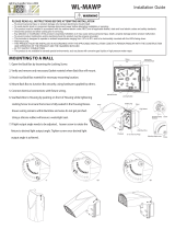
Cut off shield
(optional)
Ambient temperature for lighting fixture: -40°C + 40°C
SAFETY INSTRUCTIONS: Read instructions carefully before attempting to install fixture.
• All wiring should be performed by a qualified electrician.
• Disconnect power before installing or servicing. This fixture must be wired in accordance with the National Electrical
Code and applicable local codes and ordinances.
• Proper grounding is required to ensure personal safety.
• This fixture is for outdoor use and should not be used in areas with limited ventilation or high ambient temperatures.
CAUTION: Risk of fire
• WARNING: Make certain power is OFF before installing or maintaining fixture. No user serviceable parts inside.
• IMPORTANT: In order to comply with established electrical code, the installer must seal the area around the
mounting plate and the wall with silicone sealant to provide a watertight deal.
MOUNTING:
The back plate has a cast-in drill and knock-out template to match any standard recessed junction box, three 5/16” knockouts
for mounting holes B and four ½” NPS tapped holes A for surface conduit, photocell.
LOCATION:
Fixture should be located on the wall at least 18” below any overhang or other structural detail. Fixture should not be
recessed. Fixture must be positioned with lamp in horizontal position.
CLEANING & MAINTENANCE:
CAUTION: Be sure the fixture temperature is cool enough to touch. Do NOT clean or maintain while the fixture is energized.
1. Clean lens with non-abrasive glass cleaning solution.
2. Do NOT open fixture to clean the LED. Do NOT touch the LED.
Note: These instructions do not cover all details or variation in equipment, nor do they provide for every possible situation during
installation, operation or maintenance.
A: 1/2” NPS tapped holes 5/6” dia. Knockouts
C: Holes for #12 screw B

Phone: (844) LEDONE6 | Fax: 1-510-217-9461 | Web: www.ledonecorp.com
`
LOC-WP Multi Watt Series Installation Guide
INSTALLATION:
1. Separate the mounting bracket from the fixture.
2. Line up the mounting bracket and EVA gasket in desired location and mount securely. (EVA gaskets will provide
weather-tight seal).
3. Bring the fixture up to the mounting bracket and hook the bottom of the fixture onto the keyhole slot at a 45° angle
on the mounting bracket for hands-free wiring.
4. Complete the wiring to the power source and ground. (Fig. 2 & 3)
5. Bring the fixture onto an upright position and make sure the clips on the fixture slide into the keyhole on the
mounting bracket.
6. Slide down the fixture, tighten the set screw and make sure the fixture is securely mounted on the bracket.
PHOTOCELL INSTALLATION: (If comes with photocell)
The wall pack comes with a photocell preinstalled. To activate the photocell, remove the plastic cap. If you do not wish to use the photocell, keep the
plastic cap on.
Photocell may be installed in the field. Apply weatherproof silicone sealant to all plugs around the photocell and unused conduit entries.
1. Remove close-up plug on top of the wall mounting box.
2. Install the photocell and wire as per diagram Fig. 1.
3. Use photocell rated for your supply voltage.
ON-OFF WIRING:
Universal voltage driver permits operation at 100V through 277V, 50/60Hz except fixtures the factory provided with a 120V photocell.
1. Connect the BLACK fixture lead to the (+) LINE supply lead.
2. Connect the WHITE fixture lead to the (-) COMMON supply lead.
3. Connect the GREEN fixture lead to the supply ground.

Phone: (844) LEDONE6 | Fax: 1-510-217-9461 | Web: www.ledonecorp.com
`
LOC-WP Multi Watt Series Installation Guide
0-10V DIMMABLE WIRING:
Universal voltage driver permits operation at 120V through 277V, 50/60Hz. For 0-10V dimming, follow the wiring instructions in the
figure below.
1. Connect the BLACK fixture lead to the (+) LINE supply lead.
2. Connect the WHITE fixture lead to the (-) COMMON supply lead.
3. Connect the GROUND wire from fixture to supply ground. DO NOT connect the GROUND of the dimming fixture to
the output.
4. Connect the PURPLE fixture lead to the (V+) DIM lead.
5. Connect the GRAY fixture lead to the (V-) DIM lead.
6. The driver comes with dimmable leads. If it is unused, make sure the leads are properly capped (if applicable).
WATTAGE ADJUSTABLE TABLE SWITCH SETTING:
(Only for models with wattage adjustable function.)
LOC-WP-MW(20/25/40/60)50KDLV
Wattage Options
60W (LV1)
40W (LV2)
25W (LV3)
20W (LV4)
LOC-WP-MW(60/80/100/120)50KDLV
Wattage Options
120W (LV1)
100W (LV2)
80W (LV3)
60W (LV4)
Default Wattage: 60W
Default Wattage: 120W
/