LEDone FTFLHB Series Upassbar Linear High Bay Installation guide

Type
Installation guide

The LEDone FTFLHB Series Upassbar Linear High Bay is a versatile and efficient lighting solution for various commercial and industrial applications. With its adjustable lens options (30°/45°/60°/75°/90°) and universal voltage driver for 120V-277V operation, this high bay provides customized lighting distribution and energy savings. Suitable for temperatures ranging from -4°F to 104°F, it ensures reliable performance in diverse environments. Safety features such as UL-approved wire connectors and proper grounding ensure safe and code-compliant installation.

The LEDone FTFLHB Series Upassbar Linear High Bay is a versatile and efficient lighting solution for various commercial and industrial applications. With its adjustable lens options (30°/45°/60°/75°/90°) and universal voltage driver for 120V-277V operation, this high bay provides customized lighting distribution and energy savings. Suitable for temperatures ranging from -4°F to 104°F, it ensures reliable performance in diverse environments. Safety features such as UL-approved wire connectors and proper grounding ensure safe and code-compliant installation.

`
LOC-#FTFLHB Series Installation Guide
SAFETY INSTRUCTIONS: Read instructions carefully before attempting to install fixture.
CAUTION: Risk of fire
CLEANING & MAINTENANCE:
CAUTION: Be sure the fixture temperature is cool enough to touch. Do NOT clean or maintain while the fixture is energized.
1. Clean lens with non-abrasive cleaning solution.
2. Do NOT open fixture to clean the LED. Do NOT touch the LED.
Note: These instructions do not cover all details or variation in equipment, nor do they provide for every possible situation during
installation, operation or maintenance.
TROUBLESHOOTING:
1. Check that the line voltage at fixture is correct. Refer to wiring directions.
2. Be sure the fixture is grounded properly.
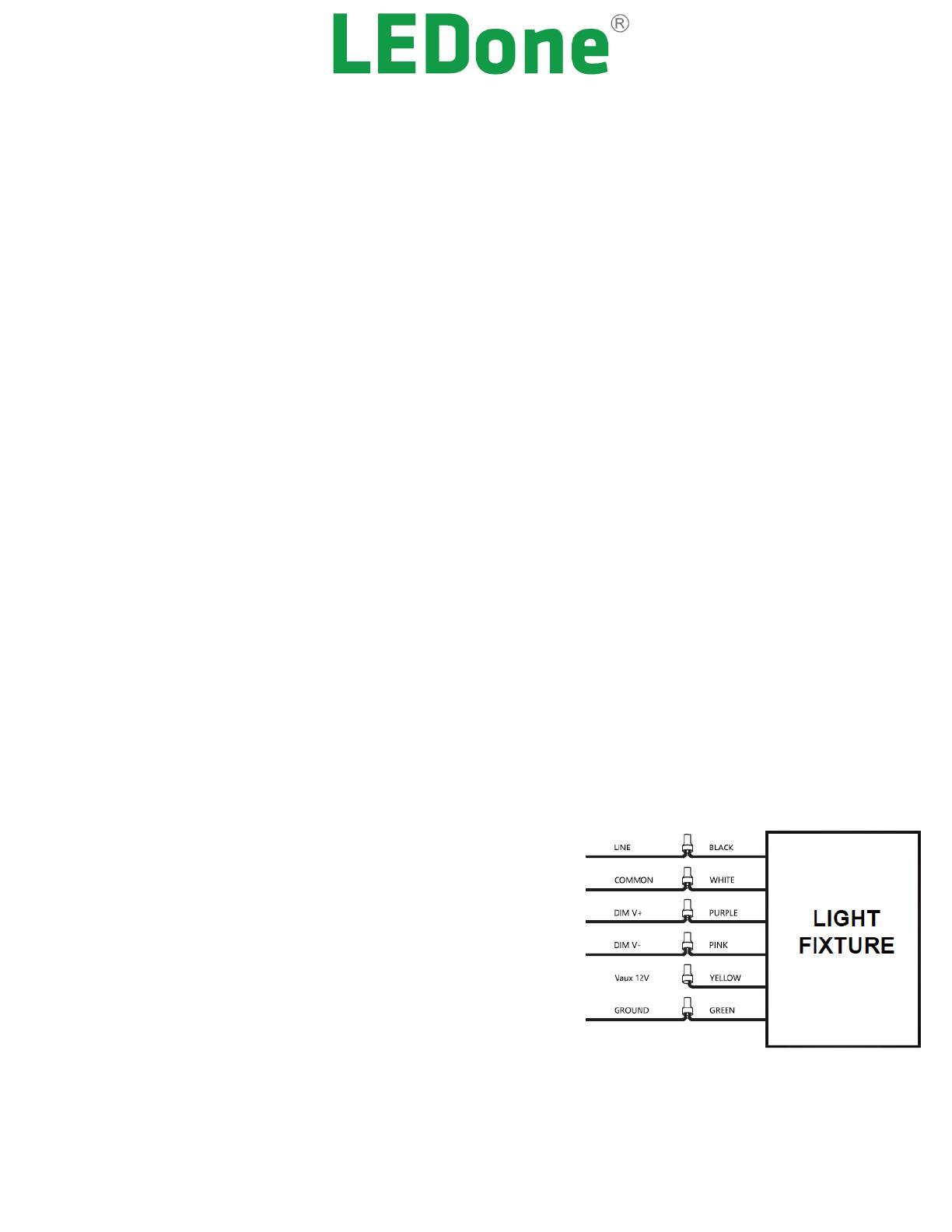
0-10V DIMMABLE WIRING:
Universal voltage driver permits operation at 120V through 277V, 50/60Hz. For 0-10V dimming, follow the wiring instructions. All units
must be connected to AC power supply.
1. Connect the BLACK fixture lead to the (+) LINE supply lead.
2. Connect the WHITE fixture lead to the (-) COMMON supply lead.
3. Connect the GROUND wire from fixture to supply ground.
DO NOT connect the GROUND of the dimming fixture to the output.
4. Connect the PURPLE fixture lead to the (V+) DIM lead.
5. Connect the PINK fixture lead to the (V-) DIM lead.
6. The driver comes with dimmable leads. If it is unused, make sure
the leads are properly capped (if applicable).
V-Hook and Chain Mounting:
1. Unfold the high bay. (Step 1)
2. Wrap the chain around the ceiling or service attachment point. (Step 2)
3. Loop the chain around the ceiling or service point. Use a S or similar connector to close the loops. (Step 3)
WARNING: Make certain power is OFF before installing or maintaining fixture. No user serviceable parts inside.
WARNING: Always make sure the power is turned off before performing any maintenance.
WARNING: Verify th
at the supply voltage is correct by comparing it with the luminaire label information.
WARNING: All wirin g connections should be capped with UL approved wire connectors.
WARNING: To prevent wiring damage or abrasion, do NOT expose wiring to edges of sheet metal or other sharp objects to
lamp holder lead wires by employing applicable connectors.
WARNING: Do NOT use this product for other than intended use. To prevent early failure, luminaire should only be used in
operation environments ranging from -4°F to 104°F.
MOUNTING OPTIONS: Cables must be connected in accordance with instruction and proper standing rules.
All wiring should be performed by a qualified electrician.
Disconnect power b
efore installing or servicing. This fixture must be wired in accordance with the National Electrical Code and
applicable local cod
es and ordinances.
`
4. Slide the other end of the chain through the V-hook provided with the fixture. (Step 4)
5. Install the V-hook into the two bracket holes to support the fixture. (Step 4)
6. Remove the access plate and feed the supply wire with strain relief conduit connector through the access plate and make the
electrical connections.
7. Push all wires back into the junction box, install the plate of box with supplied screws. Be careful not to pinch the wires.
Reinstall the access plate back on and secure with the screw.
Pendant Mounting:
1. Choose length of ½ NPS ped and stem (supplied by others).
2. Install pendant mount kit including stem, junction box (sold separately), screws and washers.
3. Feed wires through the pendent stem and into the junction box.
4. Wire the housing leads to supply wires using UL listed wire connectors according to NEC and local codes in the junction box.
5. Push all wires back into the junction box, install the plate of box with supplied screws. Be careful not to pinch the wires.
6. Slide the other end of the chain through the V-hook provided with the fixture.
Surface Mounting:
1. Remove the lens from the front side of the fixture.
2. Use screws to screw into the ceiling. Make sure the screws are secured.
3. Connect the supply wires to the fixture wire leads per the wiring diagram.
LOC-#FTFLHB Series Installation Guide
`
Adjusting the Lens:
1. Push the side of adjustable strap with 1 protruded knob into the allotted hole parallel with the lens. (Fig. 1)
2. Turn it upward and then decide which angle you would like to place the lens in. (Fig. 2)
3. Line up the knob of the desired angle and push that knob into the allotted hole. (Fig. 3)
LOC-#FTFLHB Series Installation Guide
Fig. 1
Fig. 2
Fig. 3
`
LOC-#FTFLHB Series Installation Guide
30° / 45° / 60° / 75° / 90°
LO-LOC-4FTLHB-MW-350-50KD come with 4 pieces of adjustable straps
Adjustable Lens Options:
  • Page 1 1
  • Page 2 2
  • Page 3 3
  • Page 4 4

LEDone FTFLHB Series Upassbar Linear High Bay Installation guide

Type
Installation guide

The LEDone FTFLHB Series Upassbar Linear High Bay is a versatile and efficient lighting solution for various commercial and industrial applications. With its adjustable lens options (30°/45°/60°/75°/90°) and universal voltage driver for 120V-277V operation, this high bay provides customized lighting distribution and energy savings. Suitable for temperatures ranging from -4°F to 104°F, it ensures reliable performance in diverse environments. Safety features such as UL-approved wire connectors and proper grounding ensure safe and code-compliant installation.

Ask a question and I''ll find the answer in the document

Finding information in a document is now easier with AI