
© 2020
Order #XXXXX
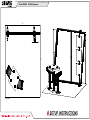
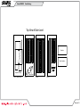
Top View
10’
10’
VK-1962 Supernova
If you would like to tell us about your experience with your setup instructions please email us at [email protected]
SETUP INSTRUCTIONS

© 2020
Order #XXXXX
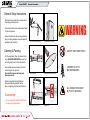
DO NOT USE POWER TOOLS
ALL CONNECTIONS MUST
BE TIGHTLY SECURED
Part Identification - Numbering
Spline Connection Base Plate & Extrusion Connection
General Setup Instructions
- Read entire setup instruction manual prior to
unpacking parts and pieces.
- The setup instructions are created specifically
for this configuration.
- Setup instructions are laid out sequentially in
steps, including exploded views with detailed
explanation for assembly.
WARNING
Cleaning & Packing
- For Cleaning Metal, Plex, & Laminate Parts:
Use a MILD NON-ABRASIVE cleanser and
soft cloth/paper towel to clean all surfaces.
- Keep exhibit components away from heat
and prolonged sun exposure.
Heat and UV exposure will warp and
fade components.
- Retain all provided Packing Materials.
All provided packing materials are for
ease of repacking & component protection.
Disassembly
- For loss prevention, tighten all set screws
and locks during disassembly.
7A
Hex Tool - Essential for Assembly
Extrusion & Lock Connection Engaged Lock
LADDERS OR LIFTS
MAY BE REQUIRED
General Information

© 2020
Order #XXXXX
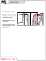
1) Locate channels along the edges of extrusions
2) Insert graphic corners first into channels then center
point of graphic into channels. Allows for proportional
fit around the perimeter of the extrusion.
3) Working from center to corner, slide silicon edge
on graphic into channel.
4) After all edges of graphic have been inserted into
channels, step back and assess graphic fit, make
adjustments where needed.
4
13
2
Fold edges over.
Insert into
groove
of frame
SEG Installation

© 2020
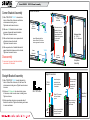
Order #XXXXX CEI110 Frame Assembly
CEI-110 Profile
Straight Bracket Assembly
1) Slide TWO-PIECE TS RV 4 straight bracket into
Interior Center Slot of extrusion, so that two of the
set screws are inside groove. Tighten two set screws
to secure.
3) Slide connecting extrusion over exposed ends of
bracket & connector. Tighten all remaining set screws
to secure extrusions.
2) Slide one V4 Connector into outer interior groove
of extrusion, so that one set screw is inside groove.
Tighten set screw.
TS RV 4
Bracket
V4
Insert two-piece
bracket into the
interior center slot
of extrusion.
Slide V4 Connector
into front interior
groove.
Secure inserted half of
bracket & connector
using set screws.
Slide connecting
extrusion over
exposed ends
of bracket &
connector.
Completed
Assembly
Secure extrusion,
using remaining
set screws.
Set
Screws
Straight Connection
Corner Connection
TS RV 2
Upper
Horizontal
Lower
Horizontal
Upper
Horizontal
Lower
Horizontal
TS RV 2
8 Brackets Total:
(4) - TS RV 2
(4) - A1 L-Brackets
A1
A1
Slide verticals over
brackets of lower
horizontal, then slide
upper horizontal &
brackets into grooves
& center slots
of verticals.
Completed
Assembly
Insert L-Brackets into the
Interior Center Slot & outer
interior grooves of extrusion.
Disassembly
1) Loosen set screws on brackets and slide
extrusions off of brackets.
1) Slide TWO-PIECE TS RV 2 L-bracket into
Interior Center Slot of extrusion so that two
set screws are inside groove.
Tighten two set screws to secure.
2) Slide one A1 L-Bracket into outer interior
grooves of upper and lower horizontals.
Tighten set screws to secure.
4) Slide exposed ends of installed brackets of
upper horizontal into open ends of verticals.
Tighten set screws to secure.
3) Slide vertical extrusion over exposed ends
of brackets in lower horizontal.
Tighten set screws to secure.
Corner Bracket Assembly
CEI-110 Frame Assembly

© 2020
Case 1 of 1
Order #XXXXX Case Packing
Graphics
Setup Hardware
Top View of Each Level
Level 1 (Bottom Level) Level 2
4 4A 5 5A
1 1A
(2)
Base Plates
2 2A
Graphics & Wings
Level 3 Level 4
3
11
10
9,9A6,6
3A

© 2020
Crate 1 of 1
Order #XXXXX Crate Packing

© 2020
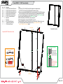
Step 1 of 3
Order #XXXXX VK-1962 Frame Assembly
7
7
8
12
3
3A
2A 1A
5A
4A
5
46
6
10 11
9
9A
Item
1,1A
2,2A
3,3A
4,4A
5,5A
6,6A
7
8
9,9A
10
11
Qty.
1,1
1,1
1,1
1,1
1,1
1,1
2
1
1,1
1
1
Description
33.6754” CEI110 Horizontal Extrusion
33.6753” CEI110 Horizontal Extrusion
33.6753“ CEI110 Horizontal Extrusion
45.6185” CEI110 Vertical Extrusion
45.6185” CEI110 Vertical Extrusion
43.1767“ Z45 Vertical Extrusion
Base Plate
Base Plate
46.5” S44 Vertical Extrusion
10” S44 Horizontal Extrusion
3” S44 Vertical Extrusion
Steps:
1) Assemble [1,2,3] [1A,2A,3A] [4,5] and [4A,5A] together with straight brackets.
See CEI110 Frame Assembly sheet Straight Bracket Assembly details.
2) Attach vertical assemblies [4/5] [4A/5A] and horizontal assemblies [1/2/3] [1A/2A/3A] together
with Corner brackets. See CEI110 Frame Assembly sheet Corner Bracket Assembly details.
3) Connect verticals [6] together then attach between [2] and [2A]. See PR53 Connector detail.
4) Attach verticals [9] and [9A] together. See PR53 Connector detail.
5) Attach base plates [7] to horizontals [1] and [2], using bolts.
6) Attach base plate [8] to vertical assembly [9/9A], using a bolt.
7) Assemble [8/9/9A] [10] and [11] then attach to top of horizontal [1A]. Tighten locks to secure.
8) Connect lighting cords and attach transformers. See Light to Light Connection and
Light to Transformer Connection details.
Completed Assembly
Power Break
Power Break
Assemble CEI110 frame flat on floor.
++
+
-
-
-
Lights
Male
Male
Female
Female
to power Transformer
144W / 6A / 24V
Light to Light Connection
Light to Transformer Connection
Maximum of 14 lights per transformer.
**
PR53
Connector
Extrusion Connector
Slide upper extrusion
over connector and
rest on lower extrusion.
Secure with set screws.
*
To prevent product loss,
keep all screws attached
to connector after
disassembling.
Set Screw

© 2020
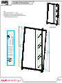
Step 2 of 3
Order #XXXXX
Wing
Wing
Wing
Graphic
Wing
Steps:
1)
Attach wings to A10 clamps. See A10 Clamp detail.
2) Attach graphics to vertical extrusion, using standoffs and screw caps.
3) Install SEG graphic to front of assembled frame and SEG blocker fabric to back.
See SEG Graphic Installation sheet for instruction.
Completed Assembly
*
*
*
*
*
*
Graphic
Graphic
*
*
*
Knob
Set Screw
Connector
1) Slide connector of clamp
into extrusion groove.
2) Tighten set screw when
A10 is in desired location.
3) Insert wing into clamp.
4) Tighten knob on clamp
to secure wing in place.
A10 Clamp
A10 Clamp
VK-1962 Frame Attachments

© 2020
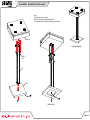
Step 3 of 3
Order #XXXXX
Completed Assembly
Underside View
Base
Bolt
Black
Bolt
Table Top
Post
Steps:
1) Connect base to post, using bolt.
2) Route cord from table top through post and base.
3) Connect table top to post, with fixed brackets, using black bolts.
Modied MOD-1454 Table Assembly
-
 1
1
-
 2
2
-
 3
3
-
 4
4
-
 5
5
-
 6
6
-
 7
7
-
 8
8
-
 9
9


SEGUE VK-1962 Supernova Setup Instructions
- Type
- Setup Instructions
- This manual is also suitable for
Ask a question and I''ll find the answer in the document
Finding information in a document is now easier with AI
Other documents
-
Classic Exhibits VK-1971 Setup Instructions
-
-
-
-
-
-
-
-
-