Page is loading ...
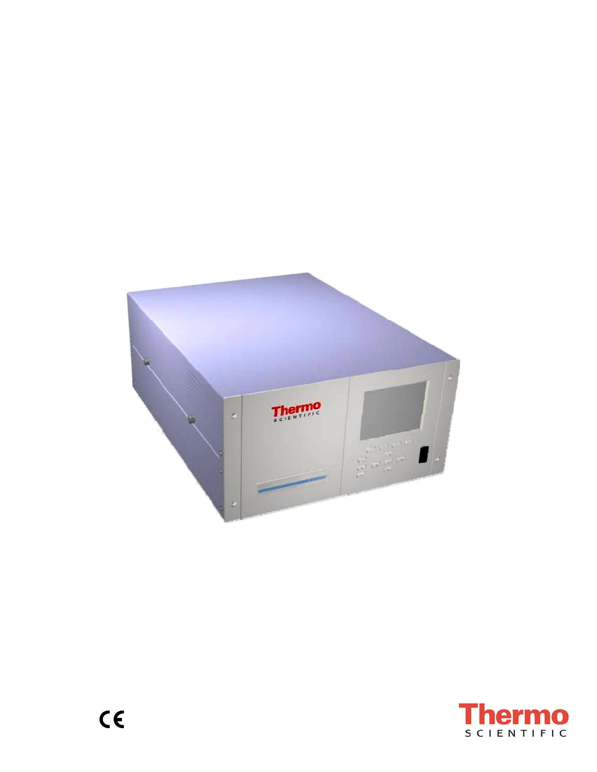
Model 42i
Instruction Manual
Chemiluminescence NO-NO2-NOx Analyzer
Part Number 101350-00
25Jul2015

© 2007 Thermo Fisher Scientific Inc. All rights reserved.
Specifications, terms and pricing are subject to change. Not all products are available in all countries. Please
consult your local sales representative for details.
Thermo Fisher Scientific
Air Quality Instruments
27 Forge Parkway
Franklin, MA 02038
1-508-520-0430
www.thermo.com/aqi

Thermo Fisher Scientific WEEE Compliance
WEEE Compliance
This product is required to comply with the European Union’s Waste
Electrical & Electronic Equipment (WEEE) Directive 2002/96/EC. It is
marked with the following symbol:
Thermo Fisher Scientific has contracted with one or more
recycling/disposal companies in each EU Member State, and this product
should be disposed of or recycled through them. Further information on
Thermo Fisher Scientific’s compliance with these Directives, the recyclers
in your country, and information on Thermo Fisher Scientific products
which may assist the detection of substances subject to the RoHS Directive
are available at: www.thermo.com/WEEERoHS.


Thermo Fisher Scientific Reference Method Designation
Reference Method Designation
The Thermo Scientific Model 42i is designated by the United States
Environmental Protection Agency (US EPA) as a Reference Method for the
measurement of ambient concentrations of nitrogen dioxide pursuant with
the requirements defined in the Code of Federal Regulations, Title 40, Part
53.
Designated Reference Method Number: RFNA-1289-074
EPA Designation Date: December 11, 1989 (amended for Model 42i)
The Model 42i Chemiluminescence NO-NO2-NOx Analyzer meets EPA
reference designation requirements when operated with the following:
Range 50 to 1000 ppb
Averaging Time 10 to 300 seconds
Temperature Range 15 to 35 C
Line Voltage 90 to 110 Vac @50/60 Hertz
105 to 125 Vac @50/60 Hertz
210 to 250 Vac @50/60 Hertz
Pressure Compensation ON or OFF
Temperature Compensation ON or OFF
Flow Rate 0.5 to 1 LPM
RS-232/RS-485 Interface
With or without the following options:
Teflon Particulate Filter
Ozone Particulate Filter
Internal Zero/Span and Sample Valves
Ozone Permeation Dryer
Permeation Oven
Rack Mounts
I/O Expansion Board


Thermo Fisher Scientific Model 42i Instruction Manual i
About This Manual
This manual provides information about operating, maintaining, and
servicing the analyzer. It also contains important alerts to ensure safe
operation and prevent equipment damage. The manual is organized into
the following chapters and appendixes to provide direct access to specific
operation and service information.
● Chapter 1 “Introduction” provides an overview of product features,
describes the principles of operation, and lists the specifications.
● Chapter 2 “Installation” describes how to unpack, setup, and startup
the analyzer.
● Chapter 3 “Operation” describes the front panel display, the front
panel pushbuttons, and the menu-driven software.
● Chapter 4 “Calibration” provides the procedures for calibrating the
analyzer and describes the required equipment.
● Chapter 5 “Preventive Maintenance” provides maintenance procedures
to ensure reliable and consistent instrument operation.
● Chapter 6 “Troubleshooting” presents guidelines for diagnosing
analyzer failures, isolating faults, and includes recommended actions for
restoring proper operation.
● Chapter 7 “Servicing” presents safety alerts for technicians working on
the analyzer, step-by-step instructions for repairing and replacing
components, and a replacement parts list. It also includes contact
information for product support and technical information.
● Chapter 8 “System Description” describes the function and location of
the system components, provides an overview of the software structure,
and includes a description of the system electronics and input/output
connections.
● Chapter 9 “Optional Equipment” describes the optional equipment
that can be used with this analyzer.
● Appendix A “Warranty” is a copy of the warranty statement.
● Appendix B “C-Link Protocol Commands” provides a description of
the C-Link protocol commands that can be used to remotely control an
analyzer using a host device such as a PC or datalogger.
About This Manual
Safety
ii Model 42i Instruction Manual Thermo Fisher Scientific
● Appendix C “MODBUS Protocol” provides a description of the
MODBUS Protocol Interface and is supported both over RS-232/485
(RTU protocol) as well as TCP/IP over Ethernet.
● Appendix D “Geysitech (Bayern-Hessen) Protocol” provides a
description of the Geysitech (Bayern-Hessen or BH) Protocol Interface
and is supported both over RS-232/485 as well as TCP/IP over
Ethernet.
Review the following safety information carefully before using the analyzer.
This manual provides specific information on how to operate the analyzer,
however, if the analyzer is used in a manner not specified by the
manufacturer, the protection provided by the equipment may be impaired.
This manual contains important information to alert you to potential safety
hazards and risks of equipment damage. Refer to the following types of
alerts you may see in this manual.
Safety and Equipment Damage Alert Descriptions
Alert Description
DANGER A hazard is present that could result in death or serious
personal injury if the warning is ignored. ▲
WARNING A hazard or unsafe practice could result in serious
personal injury if the warning is ignored. ▲
CAUTION A hazard or unsafe practice could result in minor to
moderate personal injury if the warning is ignored. ▲
Equipment Damage A hazard or unsafe practice could result in property
damage if the warning is ignored. ▲
Safety
Safety and Equipment
Damage Alerts

About This Manual
Safety and Equipment Damage Alerts
Thermo Fisher Scientific Model 42i Instruction Manual iii
Safety and Equipment damage Alerts in this Manual
Alert Description
WARNING If the equipment is operated in a manner not specified by
the manufacturer, the protection provided by the
equipment may be impaired. ▲
The service procedures in this manual are restricted to
qualified service personnel only. ▲
The Model 42i is supplied with a three-wire grounding
cord. Under no circumstances should this grounding
system be defeated. ▲
CAUTION If the LCD panel breaks, do not to let the liquid crystal
contact your skin or clothes. If the liquid crystal contacts
your skin or clothes, wash it off immediately using soap
and water. ▲
Equipment Damage Do not attempt to lift the analyzer by the cover or other
external fittings. ▲
Some internal components can be damaged by small
amounts of static electricity. A properly ground antistatic
wrist strap must be worn while handling any internal
component. ▲
This adjustment should only be performed by an
instrument service technician. ▲
Handle all printed circuit boards by the edges only. ▲
Do not remove the panel or frame from the LCD module.
▲
The LCD module polarizing plate is very fragile, handle it
carefully. ▲
Do not wipe the LCD module polarizing plate with a dry
cloth, it may easily scratch the plate. ▲
Do not use Ketonics solvent or aromatic solvent to clean
the LCD module, use a soft cloth moistened with a
naphtha cleaning solvent. ▲
Do not place the LCD module near organic solvents or
corrosive gases. ▲
Do not shake or jolt the LCD module. ▲

About This Manual
FCC Compliance
iv Model 42i Instruction Manual Thermo Fisher Scientific
Changes or modifications to this unit not expressly approved by the party
responsible for compliance could void the user’s authority to operate the
equipment.
Note This equipment has been tested and found to comply with the limits
for a Class A digital device, pursuant to Part 15 of the FCC Rules. These
limits are designed to provide reasonable protection against harmful
interference when the equipment is operated in a commercial environment.
This equipment generates, uses, and can radiate radio frequency energy
and, if not installed and used in accordance with the instruction manual,
may cause harmful interference to radio communications. Operation of this
equipment in a residential area is likely to cause harmful interference in
which case the user will be required to correct the interference at his own
expense. ▲
The following symbol and description identify the WEEE marking used on
the instrument and in the associated documentation.
Symbol Description
Marking of electrical and electronic equipment which applies to waste
electrical and electronic equipment falling under the Directive 2002/96/EC
(WEEE) and the equipment that has been put on the market after 13 August
2005. ▲
Service is available from exclusive distributors worldwide. Contact one of
the phone numbers below for product support and technical information
or visit us on the web at www.thermo.com/aqi.
1-866-282-0430 Toll Free
1-508-520-0430 International
FCC Compliance
W
EEE Symbol
W
here to Get Help

Thermo Fisher Scientific Model 42i Instruction Manual v
Contents
Introduction ........................................................................................................ 1-1
Principle of Operation ........................................................................ 1-2
Specifications ...................................................................................... 1-3
Installation ......................................................................................................... 2-1
Lifting ................................................................................................. 2-1
Unpacking and Inspection .................................................................. 2-1
Setup Procedure .................................................................................. 2-3
Connecting External Devices .............................................................. 2-5
Terminal Board PCB Assemblies ...................................................... 2-5
I/O Terminal Board ...................................................................... 2-5
D/O Terminal Board .................................................................... 2-7
25-Pin Terminal Board ................................................................. 2-8
Startup ................................................................................................ 2-9
Operation ............................................................................................................ 3-1
Display ................................................................................................ 3-1
Pushbuttons ........................................................................................ 3-2
Soft Keys .......................................................................................... 3-3
Alphanumeric Entry Screen .............................................................. 3-4
Firmware Overview ............................................................................. 3-4
Power-Up Screen ............................................................................. 3-6
Run Screen ....................................................................................... 3-6
Main Menu ...................................................................................... 3-7
Range Menu ....................................................................................... 3-8
Single Range Mode .......................................................................... 3-8
Dual Range Mode ............................................................................ 3-9
Auto Range Mode .......................................................................... 3-11
Gas Units ....................................................................................... 3-13
NO, NO2, and NOx Ranges ........................................................... 3-13
Set Custom Ranges ........................................................................ 3-15
Custom Ranges ........................................................................... 3-16
Averaging Time ................................................................................. 3-16
Calibration Factors Menu ................................................................. 3-17
NO and NOx Backgrounds ............................................................ 3-17
NO, NO2, and NOx Coefficients ................................................... 3-19
Reset User Calibration Defaults ..................................................... 3-19
Calibration Menu ............................................................................. 3-20
Calibrate NO and NOx Backgrounds ............................................. 3-20
Chapter 1
Chapter 2
Chapter 3

Contents
vi Model 42i Instruction Manual Thermo Fisher Scientific
Calibrate NO, NO2, and NOx Coefficients .................................... 3-21
Zero/Span Check ........................................................................... 3-21
Next Time .................................................................................. 3-22
Period Hours ............................................................................... 3-22
Total Duration Hour .................................................................. 3-23
Zero/Span/Purge Duration Minutes ........................................... 3-23
Zero/Span Averaging Time ......................................................... 3-23
Zero/Span Calibration Reset ....................................................... 3-24
Zero/Span Ratio .......................................................................... 3-24
Instrument Controls Menu ............................................................... 3-24
Ozonator ........................................................................................ 3-25
PMT Supply .................................................................................. 3-26
Auto/Manual Mode ....................................................................... 3-26
Datalogging Settings ...................................................................... 3-26
Select Srec/Lrec ........................................................................... 3-27
View Logged Data ....................................................................... 3-28
Number of Records ..................................................................... 3-28
Date and Time ............................................................................ 3-28
Erase Log .................................................................................... 3-29
Select Content ............................................................................. 3-29
Choose Field Data ....................................................................... 3-30
Concentrations ............................................................................ 3-30
Other Measurements ................................................................... 3-31
Analog Inputs .............................................................................. 3-32
Commit Content ........................................................................ 3-32
Reset to Default Content ............................................................ 3-32
Configure Datalogging ................................................................ 3-33
Logging Period Min .................................................................... 3-33
Memory Allocation Percent ......................................................... 3-33
Data Treatment .......................................................................... 3-34
Communication Settings ................................................................ 3-34
Serial Settings .............................................................................. 3-35
Baud Rate ................................................................................... 3-35
Data Bits ..................................................................................... 3-35
Parity .......................................................................................... 3-36
Stop Bits ..................................................................................... 3-36
RS-232/RS-485 Selection ............................................................ 3-36
Instrument ID ............................................................................. 3-37
Communication Protocol ............................................................ 3-37
Streaming Data Configuration .................................................... 3-38
Streaming Data Interval .............................................................. 3-38
Choose Stream Data ................................................................... 3-39
Concentrations ............................................................................ 3-39
Other Measurements ................................................................... 3-40
Analog Inputs .............................................................................. 3-40
TCP/IP Settings .......................................................................... 3-41

Contents
Thermo Fisher Scientific Model 42i Instruction Manual vii
Use DHCP ................................................................................. 3-41
IP Address ................................................................................... 3-42
Netmask ...................................................................................... 3-42
Default Gateway ......................................................................... 3-42
Host Name ................................................................................. 3-43
Network Time Protocol Server .................................................... 3-43
I/O Configuration .......................................................................... 3-43
Output Relay Settings ................................................................. 3-44
Logic State .................................................................................. 3-44
Instrument State ......................................................................... 3-45
Alarms ......................................................................................... 3-45
Non-Alarm ................................................................................. 3-46
Digital Input Settings .................................................................. 3-47
Logic State .................................................................................. 3-47
Instrument Action ....................................................................... 3-48
Analog Output Configuration (Select Channel) .......................... 3-48
Allow Over/Under Range ............................................................ 3-48
Analog Output Configuration (Select Action) ............................. 3-49
Select Range ................................................................................ 3-49
Minimum and Maximum Value ................................................. 3-50
Choose Signal to Output ............................................................ 3-51
Analog Input Configuration ........................................................ 3-53
Descriptor ................................................................................... 3-53
Units ........................................................................................... 3-54
Decimal Places ............................................................................ 3-54
Number of Table Points .............................................................. 3-54
Table Point ................................................................................. 3-55
Volts ........................................................................................... 3-55
User Value .................................................................................. 3-56
Temperature Compensation ........................................................... 3-56
Pressure Compensation .................................................................. 3-57
Screen Contrast .............................................................................. 3-57
Service Mode ................................................................................. 3-58
Date/Time ..................................................................................... 3-58
Timezone ....................................................................................... 3-59
Diagnostics Menu ............................................................................. 3-59
Program Version ............................................................................ 3-60
Voltages ......................................................................................... 3-60
Motherboard Voltages ................................................................. 3-61
Interface Board Voltages ............................................................. 3-61
I/O Board Voltages ..................................................................... 3-61
Temperatures ................................................................................. 3-62
Pressure .......................................................................................... 3-62
Flow ............................................................................................... 3-62
Analog Input Readings ................................................................... 3-63
Analog Input Voltages .................................................................... 3-63

Contents
viii Model 42i Instruction Manual Thermo Fisher Scientific
Digital Inputs ................................................................................. 3-63
Relay States .................................................................................... 3-64
Test Analog Outputs ...................................................................... 3-64
Set Analog Outputs ..................................................................... 3-64
Instrument Configuration .............................................................. 3-65
Contact Information ...................................................................... 3-65
Alarms Menu .................................................................................... 3-66
Internal Temperature ..................................................................... 3-67
Min and Max Internal Temperature Limits ................................. 3-67
Chamber Temperature ................................................................... 3-67
Min and Max Chamber Temperature Limits .............................. 3-68
Cooler Temperature ....................................................................... 3-68
Min and Max Cooler Temperature Limits .................................. 3-68
Converter Temperature .................................................................. 3-69
Min and Max Converter Temperature Limits ............................. 3-69
Permeation Oven Gas Temperature ............................................... 3-69
Min and Max Permeation Oven Temperature Limits .................. 3-70
Pressure .......................................................................................... 3-70
Min and Max Pressure Limits ..................................................... 3-71
Flow ............................................................................................... 3-71
Min and Max Flow Limits .......................................................... 3-71
Ozonator Flow ............................................................................... 3-72
Zero and Span Check ..................................................................... 3-72
Max Zero and Span Check Offset ............................................... 3-72
Zero and Span Auto Calibration .................................................... 3-73
NO, NO2, and NOx Concentration ............................................... 3-73
Min and Max NO, NO2, and NOx Concentration Limits ........... 3-74
Min Trigger ................................................................................ 3-74
External Alarms .............................................................................. 3-74
Service Menu .................................................................................... 3-75
PMT Voltage Adjustment .............................................................. 3-75
Range Mode Select ......................................................................... 3-76
Converter Set Temperature ............................................................ 3-76
Pressure Calibration ....................................................................... 3-77
Calibrate Pressure Zero ............................................................... 3-77
Calibrate Pressure Span ............................................................... 3-78
Restore Default Pressure Calibration ........................................... 3-78
Flow Calibration ............................................................................ 3-78
Calibrate Flow Zero .................................................................... 3-79
Calibrate Flow Span .................................................................... 3-79
Restore Default Flow Calibration ................................................ 3-80
Input Board Calibration ................................................................. 3-80
Manual Input Calibration ........................................................... 3-81
Automatic Input Calibration ....................................................... 3-81
Input Frequency Display ............................................................. 3-82
Temperature Calibration ................................................................ 3-82

Contents
Thermo Fisher Scientific Model 42i Instruction Manual ix
Analog Output Calibration ............................................................ 3-83
Analog Output Calibrate Zero .................................................... 3-84
Analog Output Calibrate Full-Scale ............................................ 3-84
Analog Input Calibration ............................................................... 3-84
Analog Input Calibrate Zero ....................................................... 3-85
Analog Input Calibrate Full-Scale ............................................... 3-85
Permeation Oven Settings .............................................................. 3-86
Calibrate Gas Thermistor ............................................................ 3-86
Water Bath .................................................................................. 3-87
Resistor ....................................................................................... 3-87
Calibrate Oven Thermistor ......................................................... 3-87
Permeation Oven Selection ......................................................... 3-88
Factory Calibrate Gas Thermistor ............................................... 3-88
Low and High Points .................................................................. 3-88
Set Defaults ................................................................................. 3-89
Factory Calibrate Oven Thermistor ............................................. 3-89
Low and High Points .................................................................. 3-89
Set Defaults ................................................................................. 3-90
Ozonator Safety ............................................................................. 3-90
Extended Ranges ............................................................................ 3-91
Dilution Ratio ................................................................................ 3-91
Display Pixel Test .......................................................................... 3-91
Restore User Defaults ..................................................................... 3-92
Password Menu ................................................................................. 3-92
Set Password .................................................................................. 3-93
Lock Instrument ............................................................................ 3-93
Lock/Unlock and Local/Remote Operation ................................ 3-93
Change Password ........................................................................... 3-94
Remove Password ........................................................................... 3-94
Unlock Instrument ......................................................................... 3-94
Calibration .......................................................................................................... 4-1
Equipment Required ........................................................................... 4-1
Zero Gas Generator.......................................................................... 4-2
Compression ................................................................................. 4-2
Drying .......................................................................................... 4-2
Oxidation ...................................................................................... 4-2
Scrubbing ...................................................................................... 4-2
Gas Phase Titrator............................................................................ 4-3
Flow Controllers ........................................................................... 4-3
Pressure Regulator ......................................................................... 4-3
Ozone Generator .......................................................................... 4-4
Diverter Valve ............................................................................... 4-4
Reaction Chamber ........................................................................ 4-4
Mixing Chamber ........................................................................... 4-4
Output Manifold .......................................................................... 4-4
Chapter 4

Contents
x Model 42i Instruction Manual Thermo Fisher Scientific
Reagents ........................................................................................... 4-4
NO Concentration Standard ......................................................... 4-4
Assaying a Working NO Standard Against a NIST-traceable NO
Standard ........................................................................................ 4-5
Zero Air ........................................................................................ 4-6
Dynamic Parameter Specifications for Gas Titrator .......................... 4-6
Determining GPT System Flow Conditions ................................. 4-6
Pre-Calibration ................................................................................... 4-8
Calibration .......................................................................................... 4-9
Connect GPT Apparatus to the Analyzer ......................................... 4-9
Adjust Instrument Gain ................................................................. 4-10
Set NO and NOx Background to Zero ........................................ 4-10
Calibrate the NO Channel to the NO Calibration Gas ............... 4-11
Calibrate the NOx Channel to the NOx Calibration Gas ............. 4-12
Preparing NO, NOx, and NO2 Calibration Curves ..................... 4-13
Alternative Calibration Procedure Using NO2 Permeation Tube .... 4-16
Calibration in Dual Range and Auto Range Mode ............................ 4-16
Set NO and NOx Background Readings to Zero ............................ 4-16
Calibrate Low NO ......................................................................... 4-17
Calibrate Low NOx ........................................................................ 4-17
Calibrate Low NO2 ........................................................................ 4-18
Calibrate High NO ........................................................................ 4-19
Calibrate High NOx ....................................................................... 4-19
Calibrate High NO2 ....................................................................... 4-19
Zero and Span Check ........................................................................ 4-20
Preventive Maintenance ................................................................................. 5-1
Safety Precautions ............................................................................... 5-1
Replacement Parts ............................................................................... 5-2
Cleaning the Outside Case .................................................................. 5-2
Ozonator Air Feed Drying Column Replacement ............................... 5-2
Capillaries Inspection and Replacement .............................................. 5-2
Thermoelectric Cooler Fins Inspection and Cleaning .......................... 5-4
Fan Filters Inspection and Cleaning .................................................... 5-4
Pump Rebuilding ................................................................................ 5-5
Troubleshooting ................................................................................................. 6-1
Safety Precautions ............................................................................... 6-1
Troubleshooting Guides ...................................................................... 6-1
Board-Level Connection Diagrams ..................................................... 6-6
Connector Pin Descriptions ................................................................ 6-8
Service Locations ............................................................................... 6-21
Servicing ............................................................................................................. 7-1
Safety Precautions ............................................................................... 7-2
Chapter 5
Chapter 6
Chapter 7

Contents
Thermo Fisher Scientific Model 42i Instruction Manual xi
Firmware Updates ............................................................................... 7-4
Accessing the Service Mode ................................................................. 7-4
Replacement Parts List ........................................................................ 7-4
Cable List ............................................................................................ 7-6
External Device Connection Components .......................................... 7-6
Removing the Measurement Bench and Lowering the Partition Panel 7-8
Pump Replacement ............................................................................. 7-9
Fan/Filter Replacement ..................................................................... 7-10
PMT Cooler and Reaction Chamber Assembly Replacement ............ 7-11
Photomultiplier Tube Replacement .................................................. 7-13
PMT High Voltage Power Supply Replacement ................................ 7-14
PMT Voltage Adjustment ................................................................. 7-16
Reaction Chamber Cleaning or Removal .......................................... 7-17
NO2-to-NO Converter Replacement ................................................ 7-18
Solenoid Valve Replacement ............................................................. 7-20
Ozonator Assembly Replacement ...................................................... 7-21
Ozonator Transformer Replacement ................................................. 7-23
Input Board Replacement ................................................................. 7-23
Input Board Calibration .................................................................... 7-25
DC Power Supply Replacement ........................................................ 7-25
Analog Output Testing ..................................................................... 7-26
Analog Output Calibration ............................................................... 7-29
Analog Input Calibration .................................................................. 7-30
Calibrating the Input Channels to Zero Volts ................................ 7-30
Calibrating the Input Channels to Full-Scale ................................. 7-30
Pressure Transducer Assembly Replacement ...................................... 7-31
Pressure Transducer Calibration ........................................................ 7-32
Temperature Control Board Replacement ......................................... 7-34
Ambient Temperature Calibration .................................................... 7-35
Fuse Replacement ............................................................................. 7-36
Scrubber Replacement ....................................................................... 7-36
I/O Expansion Board (Optional) Replacement ................................. 7-37
Digital Output Board Replacement ................................................... 7-39
Motherboard Replacement ................................................................ 7-39
Measurement Interface Board Replacement ...................................... 7-40
Flow Transducer Replacement .......................................................... 7-41
Flow Transducer Calibration ............................................................. 7-42
Front Panel Board Replacement ........................................................ 7-44
LCD Module Replacement ............................................................... 7-45
Service Locations ............................................................................... 7-46
System Description .......................................................................................... 8-1
Hardware ............................................................................................ 8-1
NO2-to-NO Converter ....................................................................... 8-2
Mode Solenoid ................................................................................. 8-2
Reaction Chamber .............................................................................. 8-2
Chapter 8

Contents
xii Model 42i Instruction Manual Thermo Fisher Scientific
Optical Filter .................................................................................... 8-3
Pressure Transducer ......................................................................... 8-3
Sample Flow Sensor ......................................................................... 8-3
Ozonator ............................................................................................. 8-3
Ozonator Flow Switch ..................................................................... 8-3
Photomultiplier Tube ......................................................................... 8-3
Photomultiplier Tube Cooler .............................................................. 8-3
Pump .................................................................................................. 8-3
Sample Capillary .............................................................................. 8-3
Dry Air Capillary ............................................................................. 8-4
Software .............................................................................................. 8-4
Instrument Control .......................................................................... 8-4
Monitoring Signals ........................................................................... 8-4
Measurement Calculations ............................................................... 8-5
Output Communication .................................................................. 8-5
Electronics .......................................................................................... 8-6
Motherboard .................................................................................... 8-6
External Connectors ...................................................................... 8-6
Internal Connectors ...................................................................... 8-6
Measurement Interface Board .......................................................... 8-7
Measurement Interface Board Connectors ..................................... 8-7
Flow Sensor Assembly ...................................................................... 8-7
Pressure Sensor Assembly ................................................................. 8-7
Temperature Control Board ............................................................. 8-7
PMT Power Supply Assembly .......................................................... 8-8
Input Board Assembly ...................................................................... 8-8
Digital Output Board ....................................................................... 8-8
I/O Expansion Board (Optional) ..................................................... 8-8
Front Panel Connector Board .......................................................... 8-9
I/O Components ................................................................................. 8-9
Analog Voltage Outputs ................................................................... 8-9
Analog Current Outputs (Optional) .............................................. 8-10
Analog Voltage Inputs (Optional) .................................................. 8-10
Digital Relay Outputs .................................................................... 8-10
Digital Inputs ................................................................................. 8-10
Serial Ports ..................................................................................... 8-11
RS-232 Connection ....................................................................... 8-11
RS-485 Connection ....................................................................... 8-12
Ethernet Connection ...................................................................... 8-12
External Accessory Connector ........................................................ 8-12
Optional Equipment ........................................................................................... 9-1
Internal Zero/Span and Sample Valves ................................................ 9-1
Internal Permeation Span Source ........................................................ 9-2
Permeation Tube Installation ........................................................... 9-3
Computation of Concentrations ...................................................... 9-4
Chapter 9

Contents
Thermo Fisher Scientific Model 42i Instruction Manual xiii
Oven Installation and Configuration ................................................ 9-4
Permeation Tube Oven Calibration ................................................. 9-6
Setting Perm Oven Temperature ................................................... 9-6
Setting Temperature with Water Bath ........................................... 9-7
Setting Temperature with Known Resistance ................................ 9-8
Determining Permeation Rate by Weight Loss ................................. 9-9
Determining Release Rate by Transfer Standard............................... 9-9
Ozonator Permeation Dryer .............................................................. 9-10
Sample Permeation Dryer ................................................................. 9-10
Lag Volume ...................................................................................... 9-10
Principle of Operation ................................................................... 9-10
Lag Volume Test ............................................................................ 9-12
Ammonia Scrubber ........................................................................... 9-12
Teflon Particulate Filter .................................................................... 9-12
Ozone Particulate Filter .................................................................... 9-13
NO2-to-NO Converter ..................................................................... 9-13
I/O Expansion Board Assembly ......................................................... 9-13
25 Pin Terminal Board Assembly ...................................................... 9-13
Terminal Block and Cable Kits ......................................................... 9-13
Cables ............................................................................................... 9-14
Mounting Options ............................................................................ 9-15
Warranty ............................................................................................................ A-1
Warranty ............................................................................................. A-1
C-Link Protocol Commands ............................................................................ B-1
Instrument Identification Number ...................................................... B-1
Commands ......................................................................................... B-2
Convert Concentration Formats ....................................................... B-3
Commands List ................................................................................ B-3
Measurements ................................................................................... B-10
Alarms ............................................................................................... B-14
Diagnostics ....................................................................................... B-18
Datalogging....................................................................................... B-19
Calibration ........................................................................................ B-27
Keys/Display ..................................................................................... B-33
Measurement Configuration ............................................................. B-35
Hardware Configuration ................................................................... B-39
Communications Configuration ....................................................... B-43
I/O Configuration ............................................................................. B-49
Record Layout Definition ................................................................. B-55
Format Specifier for ASCII Responses ............................................ B-55
Format Specifier for Binary Responses ........................................... B-56
Format Specifier for EREC Layout ................................................. B-56
Text ............................................................................................ B-56
Appendix A
Appendix B

Contents
xiv Model 42i Instruction Manual Thermo Fisher Scientific
Value String ................................................................................ B-57
Value Source ............................................................................... B-57
Alarm Information ...................................................................... B-57
Translation Table ........................................................................ B-57
Selection Table ............................................................................ B-57
Button Designator....................................................................... B-58
Examples ..................................................................................... B-59
MODBUS Protocol ............................................................................................ C-1
Serial Communication Parameters ..................................................... C-1
TCP Communication Parameters ...................................................... C-2
Application Data Unit Definition ...................................................... C-2
Slave Address ................................................................................... C-2
MBAP Header ................................................................................ C-2
Function Code ................................................................................ C-3
Data ................................................................................................ C-3
Error Check .................................................................................... C-3
Function Codes .................................................................................. C-3
(0x01/0x02) Read Coils / Read Inputs ............................................ C-3
(0x03/0x04) Read Holding Registers / Read Input Registers ........... C-5
(0x05) Force (Write) Single Coil ..................................................... C-7
MODBUS Parameters Supported ...................................................... C-8
Reading a Write Coil .................................................................... C-14
Geysitech (Bayern-Hessen) Protocol ........................................................... D-1
Serial Communication Parameters ..................................................... D-1
TCP Communication Parameters ...................................................... D-2
Instrument Address ............................................................................ D-2
Abbreviations Used ............................................................................ D-2
Basic Command Structure ................................................................. D-2
Block Checksum Characters <BCC> .................................................. D-3
Geysitech Commands ........................................................................ D-3
Instrument Control Command (ST) ............................................... D-3
Data Sampling/Data Query Command (DA) .................................. D-4
Measurements reported in response to DA command ..................... D-6
Single Range Mode ...................................................................... D-6
Dual/Auto Range Mode ............................................................... D-6
Operating and Error Status ............................................................. D-6
Appendix C
Appendix D
/