Teledyne API T200 User manual
- Category
- Measuring, testing & control
- Type
- User manual

O
peration Manual
Model T200
NO/NO
2
/NO
X
Analyzer
Also supports operation of:
when used in conjunction with:
Model T200U Analyzer
T200U addendum, PN 06861
Model T200U-NOy Analyzer
T200U addendum, PN 06861 and
T200U-NOy addendum, PN 07303
T200UP Photolytic Analyzer
T200UP addendum, PN 07450
Model T201 Analyzer
T201 addendum, PN 07271
Model T265 Analyzer
T265 addendum, PN 07337
© Teledyne API(TAPI)
9970 Carroll Canyon Road
San Diego, CA 92131
USA
Toll-free Phone:
800-324-5190
Phone:
858-657-9800
Fax:
858-657-9816
Email:
Website:
http://www.teledyne-api.com/
Copyright 2010-2018
06858F DCN8038
Teledyne API
04 December 2018


i
NOTICE OF COPYRIGHT
© 2010-2018 Teledyne Advanced Pollution Instrumentation. All rights reserved.
TRADEMARKS
All trademarks, registered trademarks, brand names or product names
appearing in this document are the property of their respective owners and are
used herein for identification purposes only.
06858F DCN8038

ii
This page intentionally left blank.
06858F DCN8038

iii
SAFETY MESSAGES
Important safety messages are provided throughout this manual for the purpose of
avoiding personal injury or instrument damage. Please read these messages carefully.
Each safety message is associated with a safety alert symbol, and are placed throughout
this manual and inside the instrument. The symbols with messages are defined as follows:
WARNING: Electrical Shock Hazard
HAZARD: Strong oxidizer
GENERAL WARNING/CAUTION: Read the accompanying message for
specific information.
CAUTION: Hot Surface Warning
Do Not Touch: Touching some parts of the instrument without protection or
proper tools could result in damage to the part(s) and/or the instrument.
Technician Symbol: All operations marked with this symbol are to be
performed by qualified maintenance personnel only.
Electrical Ground: This symbol inside the instrument marks the central
safety grounding point for the instrument.
CAUTION
GENERAL SAFETY HAZARD
The T200 Analyzer should only be used for the purpose and in the
manner described in this manual. If you use the T200 in a manner other
than that for which it was intended, unpredictable behavior could ensue
with possible hazardous consequences.
NEVER use any gas analyzer to sample combustible gas(es).
Note
Technical Assistance regarding the use and maintenance of any Teledyne API
product can be obtained by contacting Teledyne API’s Technical Support
Department:
Phone: 800-324-5190
Email: api-techsupport@teledyne.com
or by accessing the service optio
ns on our website at http://www.teledyne-api.com.
06858F DCN8038

iv
CONSIGNES DE SÉCURITÉ
Des consignes de sécurité importantes sont fournies tout au long du présent manuel dans
le but d’éviter des blessures corporelles ou d’endommager les instruments. Veuillez lire
attentivement ces consignes. Chaque consigne de sécurité est représentée par un
pictogramme d’alerte de sécurité; ces pictogrammes se retrouvent dans ce manuel et à
l’intérieur des instruments. Les symboles correspondent aux consignes suivantes :
AVERTISSEMENT : Risque de choc électrique
DANGER : Oxydant puissant
AVERTISSEMENT GÉNÉRAL / MISE EN GARDE : Lire la consigne
complémentaire pour des renseignements spécifiques
MISE EN GARDE : Surface chaude
Ne pas toucher : Toucher à certaines parties de l’instrument sans protection ou
sans les outils appropriés pourrait entraîner des dommages aux pièces ou à
l’instrument.
Pictogramme « technicien » : Toutes les opérations portant ce symbole doivent
être effectuées uniquement par du personnel de maintenance qualifié.
Mise à la terre : Ce symbole à l’intérieur de l’instrument détermine le point central
de la mise à la terre sécuritaire de l’instrument.
MISE EN GARDE
Cet instrument doit être utilisé aux fins décrites et de la manière décrite dans
ce manuel. Si vous utilisez cet instrument d’une autre manière que celle pour
laquelle il a été prévu, l’instrument pourrait se comporter de façon imprévisible
et entraîner des conséquences dangereuses.
NE JAMAIS utiliser un analyseur de gaz pour échantillonner des gaz
combustibles!
06858F DCN8038

v
WARRANTY
WARRANTY POLICY (02024 J)
Teledyne Advanced Pollution Instrumentation (TAPI), a business unit of Teledyne
Instruments, Inc., provides that:
Prior to shipment, TAPI equipment is thoroughly inspected and tested. Should equipment
failure occur, TAPI assures its customers that prompt service and support will be available.
(For the instrument-specific warranty period, please refer to the “Limited Warranty” section
in the Terms and Conditions of Sale on our website at the following link:
http://www.teledyne-api.com/terms_and_conditions.asp).
COVERAGE
After the warranty period and throughout the equipment lifetime, TAPI stands ready to
provide on-site or in-plant service at reasonable rates similar to those of other manufacturers
in the industry. All maintenance and the first level of field troubleshooting are to be
performed by the customer.
NON-TAPI MANUFACTURED EQUIPMENT
Equipment provided but not manufactured by TAPI is warranted and will be repaired to the
extent and according to the current terms and conditions of the respective equipment
manufacturer’s warranty.
PRODUCT RETURN
All units or components returned to Teledyne API should be properly packed for
handling and returned freight prepaid to the nearest designated Service Center. After the
repair, the equipment will be returned, freight prepaid.
T
he complete Terms and Conditions of Sale can be reviewed at
http://www.teledyne-
api.com/terms_and_conditions.asp
C
AUTION – Avoid Warranty Invalidation
Failure to comply with proper anti-Electro-Static Discharge (ESD) handling and
packing instructions and Return Merc
handise Authorization (RMA) procedures
when returning parts for repair or calibration may void your warranty. For anti-
ESD handling and packing instructions please refer to the manual, Fundamentals
of ESD, PN 04786, in its “Packing Components for Return to Teledyne API’s
Customer Service” section. The manual can be downloaded from our website at
http://www.teledyne-api.com. RMA procedures can also be found on our website.
06858F DCN8038

vi
This page intentionally left blank.
06858F DCN8038

vii
CONVENTIONS USED IN THIS MANUAL
In addition to the safety symbols as presented in the Important Safety Information page,
this manual provides special notices related to the safety and effective use of the
analyzer and other pertinent information.
Special Notices appear as follows:
ATTENTION
COULD DAMAGE INSTRUMENT AND VOID WARRANTY
This special notice provides information to avoid damage to your instrument and
possibly invalidate the warranty.
IMPORTANT
IMPACT ON READINGS OR DATA
Could either affect accuracy of instrument readings or cause loss of data.
Note
Pertinent information associated with the proper care, operation or maintenance
of the analyzer or its parts.
06858F DCN8038

Table of Contents Teledyne API – T200 NO/NO
2
/NO
X
Analyzer Operation Manual
viii
TABLE OF CONTENTS
Safety Messages ............................................................................................................................................. iii
Warranty ......................................................................................................................................................... v
Conventions Used In this Manual .................................................................................................................... vii
Revision History ............................................................................................................................................. vii
1. INTRODUCTION ................................................................................................................ 15
1.1. Features ................................................................................................................................................. 15
1.2. Support Documentation .......................................................................................................................... 16
1.3. Options ................................................................................................................................................... 16
2. SPECIFICATIONS, APPROVALS, & COMPLIANCE ........................................................ 19
2.1. Specifications ......................................................................................................................................... 19
2.2. EPA Reference Designation.................................................................................................................... 20
2.3. Approvals and Certifications .................................................................................................................... 20
2.3.1. Safety .............................................................................................................................................. 20
2.3.2. EMC ................................................................................................................................................ 20
2.3.3. Other Type Certifications ................................................................................................................. 21
3. GETTING STARTED .......................................................................................................... 23
3.1. Unpacking the T200 Analyzer ................................................................................................................. 23
3.1.1. Ventilation Clearance ....................................................................................................................... 24
3.2. Instrument Layout ................................................................................................................................... 25
3.2.1. Front Panel ...................................................................................................................................... 25
3.2.2. Rear Panel ...................................................................................................................................... 29
3.2.3. Internal Chassis Layout .................................................................................................................... 31
3.3. Connections and Setup ........................................................................................................................... 33
3.3.1. Electrical Connections ..................................................................................................................... 33
3.3.2. Pneumatic Connections ................................................................................................................... 47
3.4. Startup, Functional Checks, and Initial Calibration ................................................................................... 64
3.4.1. Start Up ........................................................................................................................................... 64
3.4.2. Warning Messages .......................................................................................................................... 64
3.4.3. Functional Checks ........................................................................................................................... 67
3.4.4. Initial Calibration .............................................................................................................................. 68
3.4.4.1. Interferents ................................................................................................................................... 68
4. OVERVIEW OF OPERATING MODES .............................................................................. 73
4.1. Sample Mode ......................................................................................................................................... 74
4.1.1. Test Functions ................................................................................................................................. 74
4.1.2. Warning Messages .......................................................................................................................... 77
4.2. Calibration Mode..................................................................................................................................... 78
4.3. Setup Mode ............................................................................................................................................ 79
4.3.1. Password Security ........................................................................................................................... 79
4.3.2. Primary Setup Menu ........................................................................................................................ 79
4.3.3. Secondary Setup Menu (SETUP àMORE) ...................................................................................... 80
5. SETUP MODE MENUS ...................................................................................................... 81
5.1. SETUP à CFG: Configuration Information .............................................................................................. 81
5.2. SETUP àACAL: Automatic Calibration Option ........................................................................................ 82
5.3. SETUP àDAS: Internal Data Acquisition System .................................................................................... 82
5.4. SETUP àRNGE: Analog Output Reporting Range Configuration ............................................................ 82
5.4.1. T200 Physical Ranges ..................................................................................................................... 82
5.4.2. T200 Analog Output Reporting Ranges ............................................................................................ 82
5.4.3. SETUP à RNGE à MODE ............................................................................................................. 84
5.5. SETUP à PASS: Password Protection ................................................................................................... 93
5.6. SETUP à CLK: Setting the Internal Time-of-Day Clock .......................................................................... 96
5.6.1. Setting the Time of Day .................................................................................................................... 96
5.6.2. Adjusting the Internal Clock’s Speed ................................................................................................ 97
5.7. SETUP à COMM: Communications Ports .............................................................................................. 98
5.7.1. ID (Machine Identification) ................................................................................................................ 98
06858F DCN8038

Teledyne API – T200 NO/NO
2
/NO
X
Analyzer Operation Manual Table of Contents
ix
5.7.2. INET (Ethernet) ................................................................................................................................ 99
5.7.3. COM1[COM2] (Mode, Baude Rate and Test Port) ............................................................................ 99
5.8. SETUP à VARS: Variables Setup and Definition .................................................................................... 99
5.9. SETUP à Diag: Diagnostics Functions ................................................................................................. 102
5.9.1. Signal I/O ....................................................................................................................................... 104
5.9.2. Analog Output (DIAG AOUT) ......................................................................................................... 105
5.9.3. Analog I/O Configuration (DIAG AIO) ............................................................................................. 105
5.9.4. Test Chan Output (Selecting a Test Channel Function for Output A4) ............................................ 120
5.9.5. Optic Test ...................................................................................................................................... 122
5.9.6. Electrical Test ................................................................................................................................ 122
5.9.7. Ozone Gen Override ...................................................................................................................... 122
5.9.8. Flow Calibration ............................................................................................................................. 122
6. COMMUNICATIONS SETUP AND OPERATION ............................................................ 123
6.1. Date Terminal / Communication Equipment (DTE DCE) ........................................................................ 123
6.2. Communication Modes, Baud Rate and Port Testing ............................................................................ 123
6.2.1. Communication Modes .................................................................................................................. 124
6.2.2. Com Port Baud Rate ...................................................................................................................... 126
6.2.3. Com Port Testing ........................................................................................................................... 126
6.3. RS-232 ................................................................................................................................................. 128
6.4. RS-485 (Option) ................................................................................................................................... 128
6.5. Ethernet ................................................................................................................................................ 129
6.5.1. Configuring Ethernet Communication Manually (Static IP Address) ................................................ 129
6.5.2. Configuring Ethernet Communication Using Dynamic Host Configuration Protocol (DHCP) ............ 131
6.6. USB Port for Remote Access ................................................................................................................ 134
6.7. Communications Protocols ................................................................................................................... 136
6.7.1. MODBUS ....................................................................................................................................... 136
6.7.2. Hessen .......................................................................................................................................... 138
7. DATA ACQUISITION SYSTEM (DAS) AND APICOM ..................................................... 147
7.1. DAS Structure ....................................................................................................................................... 148
7.1.1. DAS Channels ............................................................................................................................... 148
7.1.2. Viewing DAS Data and Settings ..................................................................................................... 153
7.1.3. Editing DAS Data Channels ........................................................................................................... 154
7.2. Remote DAS Configuration ................................................................................................................... 166
7.2.1. DAS Configuration via APICOM ..................................................................................................... 166
7.2.2. DAS Configuration via Terminal Emulation Programs ..................................................................... 168
8. REMOTE OPERATION .................................................................................................... 169
8.1. Computer Mode .................................................................................................................................... 169
8.1.1. Remote Control via APICOM ......................................................................................................... 169
8.2. Interactive Mode ................................................................................................................................... 170
8.2.1. Remote Control via a Terminal Emulation Program ........................................................................ 170
8.3. Remote Access by Modem ................................................................................................................... 172
8.4. Password Security for Serial Remote Communications ......................................................................... 175
9. CALIBRATION PROCEDURES ....................................................................................... 177
9.1. Before Calibration ................................................................................................................................. 178
9.1.1. Required Equipment, Supplies, and Expendables .......................................................................... 178
9.1.2. Calibration Gases .......................................................................................................................... 179
9.1.3. Data Recording Devices ................................................................................................................ 181
9.1.4. NO
2
Conversion Efficiency (CE) ..................................................................................................... 181
9.2. Manual Calibration Checks and Calibration of the T200 Analyzer in its Base Configuration ................... 181
9.2.1. Setup for Basic Calibration Checks and Calibration ........................................................................ 182
9.2.2. Performing a Basic Manual Calibration Check ................................................................................ 183
9.2.3. Performing a Basic Manual Calibration ........................................................................................... 184
9.3. Manual Calibration with the Internal Span Gas Generator ..................................................................... 186
9.3.1. Performing “Precision” Manual Calibration when Internal Span Gas (IZS) Generator Option is
Present .................................................................................................................................................... 186
9.3.2. Setup for Calibration with the Internal Span Gas Generator ............................................................ 187
9.3.3. CAL On NO
2
Feature ..................................................................................................................... 187
06858F DCN8038

Table of Contents Teledyne API – T200 NO/NO
2
/NO
X
Analyzer Operation Manual
x
9.3.4. Performing a Manual Calibration Check with the Internal Span Gas Generator ............................... 189
9.3.5. Performing a Manual Calibration with the Internal Span Gas Generator .......................................... 190
9.4. Manual Calibration and Cal Checks with the Valve Options Installed ..................................................... 193
9.4.1. Setup for Calibration Using Valve Options ...................................................................................... 193
9.4.2. Manual Calibration Checks with Valve Options Installed ................................................................. 194
9.4.3. Manual Calibration Using Valve Options ........................................................................................ 195
9.5. Automatic Zero/Span Cal/Check (AutoCal)............................................................................................ 197
9.5.1. SETUP à ACAL: Programming and AUTO CAL Sequence ........................................................... 200
9.6. Calibration Quality Analysis .................................................................................................................. 203
9.7. Gas Flow Calibration............................................................................................................................. 204
10. EPA PROTOCOL CALIBRATION ................................................................................. 205
11. INSTRUMENT MAINTENANCE .................................................................................... 207
11.1. Maintenance Schedule........................................................................................................................ 207
11.2. Predictive Diagnostics ......................................................................................................................... 209
11.3. Maintenance Procedures .................................................................................................................... 210
11.3.1. Replacing the Sample Particulate Filter ........................................................................................ 210
11.3.2. Changing the O
3
Dryer Particulate Filter ....................................................................................... 211
11.3.3. Changing the Ozone Cleanser Chemical ...................................................................................... 212
11.3.4. Maintaining the External Sample Pump (Pump Pack) ................................................................... 214
11.3.5. Changing the Pump DFU Filter .................................................................................................... 215
11.3.6. Changing the Internal Span Gas Generator Permeation Tube ...................................................... 216
11.3.7. Changing the External Zero Air Scrubber (OPT 86C) ................................................................... 216
11.3.8. Changing the NO
2
Converter ........................................................................................................ 219
11.3.9. Cleaning the Reaction Cell ........................................................................................................... 221
11.3.10. Replacing Critical Flow Orifices .................................................................................................. 223
11.3.11. Checking for Light Leaks ............................................................................................................ 224
11.3.12. Checking for Pneumatic Leaks ................................................................................................... 225
12. TROUBLESHOOTING & SERVICE ............................................................................... 227
12.1. General Troubleshooting ..................................................................................................................... 228
12.1.1. Fault Diagnosis with WARNING Messages .................................................................................. 228
12.1.2. Fault Diagnosis With Test Functions ............................................................................................ 232
12.1.3. DIAG à SIGNAL I/O: Using the Diagnostic Signal I/O Function................................................... 233
12.2. Using the Analog Output Test Channel ............................................................................................... 235
12.3. Using the Internal Electronic Status LEDs ........................................................................................... 236
12.3.1. CPU Status Indicator.................................................................................................................... 236
12.3.2. Relay PCA Status LEDs ............................................................................................................... 236
12.4. Gas Flow Problems............................................................................................................................. 238
12.4.1. Zero or Low Flow Problems ......................................................................................................... 238
12.5. Calibration Problems ........................................................................................................................... 242
12.5.1. Negative Concentrations .............................................................................................................. 242
12.5.2. No Response ............................................................................................................................... 243
12.5.3. Unstable Zero and Span .............................................................................................................. 243
12.5.4. Inability to Span - No SPAN Button (CALS) .................................................................................. 244
12.5.5. Inability to Zero - No ZERO Button (CALZ) ................................................................................... 244
12.5.6. Non-Linear Response .................................................................................................................. 244
12.5.7. Discrepancy Between Analog Output and Display ........................................................................ 245
12.5.8. Discrepancy Between NO and NOX slopes .................................................................................. 246
12.6. Other Performance Problems .............................................................................................................. 246
12.6.1. Excessive Noise .......................................................................................................................... 246
12.6.2. Slow Response ............................................................................................................................ 246
12.6.3. Auto Zero Warnings .................................................................................................................... 247
12.7. Subsystem Checkout .......................................................................................................................... 248
12.7.1. AC Main Power ............................................................................................................................ 248
12.7.2. DC Power Supply......................................................................................................................... 249
12.7.3. I
2
C Bus ........................................................................................................................................ 250
12.7.4. LCD/Display Module .................................................................................................................... 250
12.7.5. Relay PCA ................................................................................................................................... 250
12.7.6. Motherboard ................................................................................................................................ 251
06858F DCN8038

Teledyne API – T200 NO/NO
2
/NO
X
Analyzer Operation Manual Table of Contents
xi
12.7.7. Pressure / Flow Sensor Assembly ................................................................................................ 255
12.7.8. CPU ............................................................................................................................................. 256
12.7.9. RS-232 Communications ............................................................................................................. 256
12.7.10. NO2 à NO Converter ................................................................................................................ 257
12.7.11. Determining CE by Simplified GPT Calibration ........................................................................... 262
12.7.12. Photomultiplier Tube (PMT) Sensor Module ............................................................................... 265
12.7.13. PMT Preamplifier Board ............................................................................................................. 267
12.7.14. PMT Temperature Control PCA .................................................................................................. 268
12.7.15. O
3
Generator ............................................................................................................................. 269
12.7.16. Internal Span Gas Generator and Valve Options ........................................................................ 270
12.7.17. Temperature Sensor .................................................................................................................. 271
12.8. Service Procedures............................................................................................................................. 272
12.8.1. Disk-On-Module Replacement Procedure .................................................................................... 272
12.8.2. O
3
Generator Replacement .......................................................................................................... 273
12.8.3. Sample and Ozone Dryer Replacement ....................................................................................... 273
12.8.4. PMT Sensor Hardware Calibration ............................................................................................... 274
12.8.5. Replacing the PMT, HVPS or TEC ............................................................................................... 276
12.8.6. Removing / Replacing the Relay PCA from the Instrument ........................................................... 279
12.9. Frequently Asked Questions ............................................................................................................... 280
12.10. Technical Assistance ........................................................................................................................ 281
13. PRINCIPLES OF OPERATION ...................................................................................... 283
13.1. Measurement Principle ....................................................................................................................... 283
13.1.1. Chemiluminescence Creation in the T200 Reaction Cell ............................................................... 283
13.1.2. Chemiluminescence Detection in the T200 Reaction Cell ............................................................. 285
13.1.3. NO
X
and NO
2
Determination ......................................................................................................... 286
13.1.4. Auto Zero ..................................................................................................................................... 287
13.1.5. Measurement Interferences ......................................................................................................... 288
13.2. Pneumatic Operation .......................................................................................................................... 291
13.2.1. Sample Gas Flow......................................................................................................................... 291
13.2.2. Flow Rate Control - Critical Flow Orifices ..................................................................................... 293
13.2.3. Ozone Gas Generation and Air Flow ............................................................................................ 296
13.2.4. Pneumatic Sensors ...................................................................................................................... 300
13.3. Electronic Operation ........................................................................................................................... 302
13.3.1. Overview ..................................................................................................................................... 302
13.3.2. CPU ............................................................................................................................................. 304
13.3.3. Motherboard ................................................................................................................................ 305
13.3.4. Relay PCA ................................................................................................................................... 310
13.4. Sensor Module ................................................................................................................................... 316
13.5. Photo Multiplier Tube (PMT) ............................................................................................................... 316
13.5.1. PMT Preamplifier ......................................................................................................................... 317
13.5.2. PMT Cooling System ................................................................................................................... 319
13.6. Pneumatic Sensor Board .................................................................................................................... 320
13.7. Power Supply/Circuit Breaker ............................................................................................................. 321
13.7.1. AC Power Configuration ............................................................................................................... 322
13.8. Front Panel Touchscreen/Display Interface ......................................................................................... 327
13.8.1. LVDS Transmitter Board .............................................................................................................. 328
13.8.2. Front Panel Touchscreen/Display Interface PCA .......................................................................... 328
13.9. Software Operation ............................................................................................................................. 328
13.9.1. Adaptive Filter .............................................................................................................................. 329
13.9.2. Temperature/Pressure Compensation (TPC) ................................................................................ 329
13.9.3. Calibration - Slope and Offset ...................................................................................................... 330
Glossary ...................................................................................................................................................... 331
Index ........................................................................................................................................................... 335
APPENDIX A - VERSION SPECIFIC SOFTWARE DOCUMENTATION
APPENDIX B - ELECTRONIC SCHEMATIC
S
06858F DCN8038

Table of Contents Teledyne API – T200 NO/NO
2
/NO
X
Analyzer Operation Manual
xii
FIGURES
Figure 3-1: Front Panel Layout ................................................................................................................. 25
Figure 3-2: Display Screen and Touch Control ......................................................................................... 26
Figure 3-3: Display/Touch Control Screen Mapped to Menu Charts .......................................................... 28
Figure 3-4: Rear Panel Layout – Base Unit ............................................................................................... 29
Figure 3-5: Internal Layout – Top View with IZS Option ............................................................................ 31
Figure 3-6: Internal Layout - Top View Showing Other Options ................................................................. 32
Figure 3-7: Analog In Connector ............................................................................................................... 34
Figure 3-8: Analog Output Connector ....................................................................................................... 35
Figure 3-9: Current Loop Option Installed on the Motherboard .................................................................. 36
Figure 3-10: Status Output Connector ........................................................................................................ 37
Figure 3-11: Energizing the T200 Control Inputs ......................................................................................... 38
Figure 3-12: Concentration Alarm Relay ..................................................................................................... 39
Figure 3-13 Rear Panel Connector Pin-Outs for RS-232 Mode .................................................................. 42
Figure 3-14: Default Pin Assignments for CPU COM Port Connector (RS-232). .......................................... 43
Figure 3-15: Jumper and Cables for Multidrop Mode .................................................................................. 45
Figure 3-16: RS-232-Multidrop PCA Host/Analyzer Interconnect Diagram .................................................. 46
Figure 3-17: Gas Line Connections from Calibrator – Basic T200 Configuration ......................................... 50
Figure 3-18: Gas Line Connections from Bottled Span Gas – Basic T200 Configuration ............................. 51
Figure 3-19: Pneumatics, Basic Configuration ............................................................................................ 53
Figure 3-20: Rear Panel Layout with Z/S Valve Options (OPT 50A) ............................................................ 54
Figure 3-21: Gas Line Connections for T200 with Z/S Valves Option (OPT 50A) ......................................... 54
Figure 3-22: Pneumatics with Zero/Span Valves OPT 50A ......................................................................... 56
Figure 3-23: Rear Panel Layout with Ambient Zero/Pressurized Span Valves OPT 50B.............................. 57
Figure 3-24: Gas Line Connection w/Ambient Zero/Pressurized Span Valves (OPT 50B) ........................... 58
Figure 3-25: Pneumatics with Ambient Zero/Pressurized Span Valves (OPT 50B) ...................................... 59
Figure 3-26: Rear Panel Layout with Internal Span Source (IZS) OPT 50G ................................................ 61
Figure 3-27: Pneumatics with the Internal Span Gas Generator (OPT 50G) ................................................ 62
Figure 3-28: Pneumatics for Sample Conditioner OPT 86A ........................................................................ 63
Figure 4-1: Front Panel Display ................................................................................................................ 73
Figure 4-2: Viewing T200 Test Functions ................................................................................................. 75
Figure 5-1: Analog Output Connector Pin Out ........................................................................................... 83
Figure 5-2. SETUP – COM Menu ............................................................................................................. 98
Figure 5-3. COMM– Machine ID ............................................................................................................... 99
Figure 5-4: Accessing the DIAG Submenus ............................................................................................ 103
Figure 5-5: Accessing the Analog I/O Configuration Submenus .............................................................. 106
Figure 5-6: Setup for Checking / Calibrating DCV Analog Output Signal Levels ...................................... 111
Figure 5-7: Setup for Checking / Calibration Current Output Signal Levels Using an Ammeter ................ 113
Figure 5-8: Alternative Setup Using 250Ω Resistor for Checking Current Output Signal Levels ............... 115
Figure 6-1. COM – Communication Modes Setup ................................................................................... 125
Figure 6-2. COM – COM Port Baud Rate ............................................................................................... 126
Figure 6-3. COM – COM1 Test Port ....................................................................................................... 127
Figure 6-4. COM - LAN /Internet Manual Configuration ........................................................................... 130
Figure 6-5. COM – LAN / Internet Automatic Configuration (DHCP) ........................................................ 132
Figure 6-6. COM – Change Hostname .................................................................................................. 133
Figure 7-1: Default DAS Channels Setup ............................................................................................... 152
Figure 7-2: APICOM Remote Control Program Interface ......................................................................... 166
Figure 7-3: Sample APICOM User Interface for Configuring the DAS ..................................................... 167
Figure 7-4: DAS Configuration Through a Terminal Emulation Program .................................................. 168
Figure 8-1: Remote Access by Modem ................................................................................................... 173
Figure 9-1: Set up for Manual Calibrations/Checks of T200’s in Base Configuration w/ a Gas Dilution
Calibrator ............................................................................................................................. 182
Figure 9-2: Set up for Manual Calibrations/Checks of T200’s in Base Configuration w/ Bottled Gas ........ 182
Figure 9-3: Pneumatic Connections for T200 Precision Calibration when IZS Generator Present ............ 186
Figure 9-4: Pneumatic Connections for Manual Calibration/Checks with the Internal Span Gas Generator187
Figure 11-1 Replacing the Particulate Filter ............................................................................................. 210
06858F DCN8038

Teledyne API – T200 NO/NO
2
/NO
X
Analyzer Operation Manual Table of Contents
xiii
Figure 11-2: Particle Filter on O
3
Supply Air Dryer .................................................................................... 211
Figure 11-3: Ozone Cleanser Assembly ................................................................................................... 212
Figure 11-4: Zero Air Scrubber Assembly ................................................................................................. 218
Figure 11-5: NO
2
Converter Assembly ...................................................................................................... 220
Figure 11-6: Reaction Cell Assembly ........................................................................................................ 221
Figure 11-7: Critical Flow Orifice Assembly .............................................................................................. 223
Figure 12-1: Example of Signal I/O Function ............................................................................................ 234
Figure 12-2: CPU Status Indicator ............................................................................................................ 236
Figure 12-3: Relay PCA Status LEDS Used for Troubleshooting .............................................................. 237
Figure 12-4: Location of DC Power Test Points on Relay PCA ................................................................. 249
Figure 12-5: Typical Set Up of Status Output Test .................................................................................... 253
Figure 12-6: Pressure / Flow Sensor Assembly ........................................................................................ 255
Figure 12-7: Setup for determining NO
2
à NO Efficiency – T200 Base Configuration ............................... 259
Figure 12-8: Pre-Amplifier Board Layout ................................................................................................... 275
Figure 12-9: T200 Sensor Assembly ........................................................................................................ 277
Figure 12-10: Relay PCA with AC Relay Retainer In Place ......................................................................... 279
Figure 12-11: Relay PCA Mounting Screw Locations ................................................................................. 279
Figure 13-1: Reaction Cell with PMT Tube and Optical Filter .................................................................... 285
Figure 13-2: T200 Sensitivity Spectrum .................................................................................................... 286
Figure 13-3: NO
2
à NO Conversion .......................................................................................................... 286
Figure 13-4: Pneumatic Flow During the Auto Zero Cycle ......................................................................... 288
Figure 13-5. Vacuum Manifold, Standard Configuration ............................................................................ 292
Figure 13-6: Flow Control Assembly & Critical Flow Orifice ....................................................................... 293
Figure 13-7: Location of Flow Control Assemblies & Critical Flow Orifices ................................................ 295
Figure 13-8: Ozone Generator Principle ................................................................................................... 297
Figure 13-9: Semi-Permeable Membrane Drying Process ........................................................................ 297
Figure 13-10: T200 Sample Dryer .............................................................................................................. 298
Figure 13-11: T200 Electronic Block Diagram ............................................................................................. 302
Figure 13-12: CPU Board ........................................................................................................................... 304
Figure 13-13: Relay PCA Layout (P/N 045230100) .................................................................................... 310
Figure 13-14: Relay PCA P/N 045230100 with AC Relay Retainer in Place ................................................ 311
Figure 13-15: Status LED Locations – Relay PCA ...................................................................................... 312
Figure 13-16: Heater Control Loop Block Diagram. .................................................................................... 314
Figure 13-17: Thermocouple Configuration Jumper (JP5) Pin-Outs ............................................................ 316
Figure 13-18: Basic PMT Design ................................................................................................................ 317
Figure 13-19: PMT Preamp Block Diagram ................................................................................................ 318
Figure 13-20: Typical Thermo-Electric Cooler ............................................................................................. 319
Figure 13-21: PMT Cooling System Block Diagram .................................................................................... 320
Figure 13-22: Power Distribution Block Diagram ......................................................................................... 322
Figure 13-23: Location of AC power Configuration Jumpers ....................................................................... 323
Figure 13-24: Pump AC Power Jumpers (JP7) ........................................................................................... 324
Figure 13-25: Typical Set Up of AC Heater Jumper Set (JP2) ..................................................................... 325
Figure 13-26: Typical Jumper Set (JP2) Set Up of Heaters ........................................................................ 326
Figure 13-27: Front Panel and Display Interface Block Diagram ................................................................. 327
Figure 13-28: Basic Software Operation ..................................................................................................... 328
TABLES
Table 1-1. Analyzer Options .................................................................................................................... 16
Table 3-1: Ventilation Clearance ............................................................................................................. 24
Table 3-5: Analog Output Pin Assignments ............................................................................................. 35
Table 3-6: Status Output Pin Assignments .............................................................................................. 37
Table 3-7: Control Input Pin Assignments ................................................................................................ 38
Table 3-8: Zero/Span Valves Operating States OPT 50A ........................................................................ 56
Table 3-9: Valve Operating States OPT 50B installed .............................................................................. 60
06858F DCN8038

Table of Contents Teledyne API – T200 NO/NO
2
/NO
X
Analyzer Operation Manual
xiv
Table 3-10: Internal Span Gas Generator Valve Operating States OPT 50G ............................................. 63
Table 3-11: Possible Warning Messages at Start-Up ................................................................................. 66
Table 4-1: Analyzer Operating Modes ..................................................................................................... 74
Table 4-2: Test Functions Defined ........................................................................................................... 75
Table 4-3: Warning Messages Defined .................................................................................................... 77
Table 4-4: Primary Setup Mode Features and Functions ......................................................................... 79
Table 4-5: Secondary Setup Mode Features and Functions ..................................................................... 80
Table 5-1: IND Mode Analog Output Assignments ................................................................................... 86
Table 5-2: Password Levels .................................................................................................................... 93
Table 5-3: Variable Names (VARS) ....................................................................................................... 100
Table 5-4: Diagnostic Mode (DIAG) Functions ....................................................................................... 102
Table 5-5: DIAG - Analog I/O Functions ................................................................................................ 105
Table 5-6: Analog Output Voltage Range Min/Max ................................................................................ 107
Table 5-7: Voltage Tolerances for the TEST CHANNEL Calibration ....................................................... 111
Table 5-8: Current Loop Output Check .................................................................................................. 115
Table 5-9: Test Channels Functions available on the T200’s Analog Output .......................................... 120
Table 6-1: COM Port Communication Modes ........................................................................................ 124
Table 6-2: Ethernet Status Indicators .................................................................................................... 129
Table 6-4: RS-232 Communication Parameters for Hessen Protocol ..................................................... 138
Table 6-5: Teledyne API's Hessen Protocol Response Modes ............................................................... 141
Table 6-6: Default Hessen Status Flag Assignments ............................................................................. 145
Table 7-1: Front Panel LED Status Indicators for DAS ........................................................................... 147
Table 7-2: DAS Data Channel Properties .............................................................................................. 149
Table 7-3: DAS Data Parameter Functions ............................................................................................ 157
Table 8-1: Terminal Mode Software Commands .................................................................................... 170
Table 8-2: Teledyne API's Serial I/O Command Types .......................................................................... 171
Table 9-1: IZS Option Valve States with CAL_ON_NO
2
Turned ON ....................................................... 187
Table 9-2: AUTOCAL Modes ................................................................................................................ 197
Table 9-3: AutoCal Attribute Setup Parameters ..................................................................................... 198
Table 9-4: Example AutoCal Sequence ................................................................................................. 199
Table 9-5: Calibration Data Quality Evaluation ...................................................................................... 203
Table 11-1: T200 Maintenance Schedule ................................................................................................ 208
Table 11-2: Predictive Uses for Test Functions ....................................................................................... 209
Table 12-1: Front Panel Warning Messages ............................................................................................ 230
Table 12-2: Test Functions - Indicated Failures ....................................................................................... 232
Table 12-3: Test Channel Outputs as Diagnostic Tools ........................................................................... 235
Table 12-4: Relay PCA Watchdog LED Failure Indications ...................................................................... 236
Table 12-5: Relay PCA Status LED Failure Indications ............................................................................ 237
Table 12-6: DC Power Test Point and Wiring Color Codes ...................................................................... 249
Table 12-7: DC Power Supply Acceptable Levels .................................................................................... 250
Table 12-8: Relay PCA Control Devices .................................................................................................. 250
Table 12-9: Analog Output Test Function - Nominal Values Voltage Outputs ........................................... 251
Table 12-10: Status Outputs Check .......................................................................................................... 253
Table 12-11: T200 Control Input Pin Assignments and Corresponding Signal I/O Functions ...................... 254
Table 13-1: List of Interferents ................................................................................................................ 290
Table 13-2: T200 Valve Cycle Phases..................................................................................................... 293
Table 13-3: T200 Gas Flow Rates ........................................................................................................... 295
Table 13-4: Relay PCA Status LED’s ...................................................................................................... 312
Table 13-5: Thermocouple Configuration Jumper (JP5) Pin-Outs ............................................................ 315
Table 13-6: AC Power Configuration for Internal Pumps (JP7) ................................................................ 324
Table 13-7: Power Configuration for Standard AC Heaters (JP2) ............................................................. 325
Table 13-8: Power Configuration for Optional Heaters (JP6).................................................................... 326
06858F DCN8038

15
1. INTRODUCTION
Teledyne API’s Model T200 (also referred to as T200) NO/NO
2
/NO
X
Analyzer uses
chemiluminescence detection (see Principles of Operation, Section 13, this manual),
coupled with state-of-the-art microprocessor technology to provide the sensitivity,
stability and ease of use needed for ambient or dilution CEM monitoring requirements
of nitric oxide (NO), nitrogen dioxide (NO
2
) and total nitrogen oxides (NO
x
). Along
with providing high accuracy and dependability, the T200 tracks operational parameters
and issues warnings if they fall outside diagnostic limits, as well as stores easily
retrievable data.
1.1. FEATURES
Some of the other exceptional features of your T200 NO/NO
2
/NO
X
Analyzer are:
• Ranges, 0-50 ppb to 0-20 ppm, user selectable
• Independent ranges and auto ranging
• Large, vivid, and durable graphics display with touch screen interface
• Microprocessor controlled for versatility
• Multi-tasking software to allow viewing test variables while operating
• Continuous self checking with alarms
• Permeation dryer on ozone generator
• Bi-directional RS-232, optional USB and RS-485, and 10/100Base-T Ethernet
ports for remote operation
• Front panel USB ports for peripheral devices and firmware upgrades
• Digital status outputs to provide instrument operating condition
• Adaptive signal filtering to optimize response time
• Temperature and pressure compensation
• Converter efficiency correction software
• Catalytic ozone destruct
• Comprehensive internal data logging with programmable averaging periods
• Ability to log virtually any operating parameter
• 8 analog inputs (optional)
• Internal zero and span check (optional)
06858F DCN8038

Introduction Teledyne API – T200 NO/NO
2
/NO
X
Analyzer Operation Manual
16
1.2. SUPPORT DOCUMENTATION
Download additional manuals from Teledyne API’s website at http://www.teledyne-
api.com/manuals/, to support the operation of the instrument:
• APICOM Software Manual, part number 07463
• DAS Manual, part number 02837
• Fundamentals of ESD (Electro-Static Discharge), part number 04786
1.3. OPTIONS
The options available for your analyzer are presented in Table 1-1. To order these options
or to learn more about them, please contact the Sales Department of Teledyne Advanced
Pollution Instrumentation at:
TOLL-FREE: 800-324-5190
PHONE:
+1 858-657-9800
FAX:
+1 858-657-9816
EMAIL:
apisales@teledyne.com
WEBSITE:
http://www.teledyne-api.com/
Table 1-1. Analyzer Options
Option
Option
Number
Description/Notes Reference
Pumps
Pumps meet all typical AC power supply standards while exhibiting same
pneumatic performance.
11A Ship without pump (TAPI Sales)
11B Pumpless Pump Pack (TAPI Sales)
12A Internal Pump 115V @ 60 Hz (TAPI Sales)
12B Internal Pump 220V @ 60 Hz (TAPI Sales)
12C Internal Pump 220V @ 50 Hz (TAPI Sales)
Rack Mount
Kits
Options for mounting the analyzer in standard 19” racks
20A Rack mount brackets with 26 in. (660 mm) chassis slides (TAPI Sales)
20B Rack mount brackets with 24 in. (610 mm) chassis slides (TAPI Sales)
21 Rack mount brackets only (compatible with carrying strap, Option 29) (TAPI Sales)
23 Rack mount for external pump pack (no slides) (TAPI Sales)
06858F DCN8038

Teledyne API – T200 NO/NO
2
/NO
X
Analyzer Operation Manual Introduction
17
Option
Option
Number
Description/Notes Reference
Carrying Strap/Handle
Side-mounted strap for hand-carrying analyzer
29
Extends from “flat” position to accommodate hand for carrying.
Recesses to 9mm (3/8”) dimension for storage.
Can be used with rack mount brackets, Option 21.
Cannot be used with rack mount slides.
(TAPI Sales)
CAUTION – GENERAL SAFETY HAZARD
THE T200 ANALYZER WEIGHS ABOUT 18 KG (40 POUNDS).
TO AVOID PERSONAL INJURY WE RECOMMEND THAT TWO PERSONS LIFT AND CARRY THE
ANALYZER. DISCONNECT ALL CABLES AND TUBING FROM THE ANALYZER BEFORE MOVING IT.
Analog Input and USB port
Used for connecting external voltage signals from other instrumentation (such as
meteorological instruments).
64B
Also can be used for logging these signals in the analyzer’s internal
DAS
Sections 3.3.1.2,
and 7
Current Loop Analog
Outputs
Adds isolated, voltage-to-current conversion circuitry to the analyzer’s analog
outputs.
41
Can be configured for any output range between 0 and 20 mA.
May be ordered separately for any of the analog outputs.
Can be installed at the factory or retrofitted in the field.
Sections 3.3.1.4
and 5.9.3.7
Parts Kits Spare parts and expendables
42A
Expendables Kit includes a recommended set of expendables for
one year of operation of this instrument including replacement
sample particulate filters.
Appendix B
43
Expendables Kit with IZS includes the items needed to refurbish
the zero air scrubber.
Appendix B
45
Spare Parts Kit includes spares parts for one unit.
Appendix B
Calibration Valves
Used to control the flow of calibration gases generated from external sources,
rather than manually switching the rear panel pneumatic connections.
50A
AMBIENT ZERO AND AMBIENT SPAN VALVES
Zero Air and Span Gas input supplied at ambient pressure.
Gases controlled by 2 internal valves; SAMPLE/CAL & ZERO/SPAN.
Section 3.3.2.3
50B
AMBIENT ZERO AND PRESSURIZED SPAN VALVES
Span Gas input from external, pressurized source;
Span Gas flow rate maintained at 1 ATM by critical flow orifice & vented
through Vent port.
Shutoff valve stops flow of Span Gas when in sample mode to preserve
pressurized gas source.
Zero Air created via 2-stage scrubber & dry filter unit (DFU).
Gases controlled by 2 internal valves; SAMPLE/CAL & ZERO/SPAN.
Section 3.3.2.4
50G
ZERO SCRUBBER AND INTERNAL SPAN SOURCE (IZS)
Span Gas generated from internal NO
2
permeation tube
Zero Air created by 2-stage scrubber & DFU.
Gases controlled by 2 internal valves: Sample/Cal & Zero/Span
.
Sections 3.3.2.5
and 3.3.2.6
NO
2
Permeation Tubes Replacement tubes; identical size/shape; different permeation rates.
Permeation Rate
(± 25%)
Approximate NO
2
Concentration @ 50°C
52B
421 ng/min
300ppb – 500 ppb ± 25%
(TAPI Sales)
52G
842 ng/min
0600 – 1000 ppb ± 25%
(TAPI Sales)
Each tube comes with a calibration certificate, traceable to a NIST standard,
specifying its actual effusion rate of that tube to within ± 5% @ 0.56 liters per
Section 3.3.2.5
06858F DCN8038

Introduction Teledyne API – T200 NO/NO
2
/NO
X
Analyzer Operation Manual
18
Option
Option
Number
Description/Notes Reference
minute, calibration performed at a tube temperature of 50°C.
Communication Cables For remote serial, network and Internet communication with the analyzer.
Type
Description
60A RS-232
Shielded, straight-through DB-9F to DB-25M cable, about
1.8 m long. Used to interface with older computers or
code activated switches with DB-25 serial connectors.
Section 3.3.1.8
60B RS-232
Shielded, straight-through DB-9F to DB-9F cable of about
1.8 m length.
Section 3.3.1.8
60C Ethernet
Patch cable, 2 meters long, used for Internet and LAN
communications.
Section 3.3.1.8
60D USB
Cable for direct connection between instrument (rear
panel USB port) and personal computer.
Section 3.3.1.8
USB Port
For remote connection
64A
For connection to personal computer. (Separate option only when
Option 64B, Analog Input and USB Com Port not elected).
Sections 3.3.1.8
and 6.6
Concentration Alarm Relays
Issues warning when gas concentration exceeds limits set by user.
61
Four (4) “dry contact” relays on the rear panel of the instrument. This
relay option is different from and in addition to the “Contact Closures”
that come standard on all TAPI instruments.
Section 3.3.1.7
RS-232 Multidrop Enables communications between host computer and up to eight analyzers.
62
Multidrop card seated on the analyzer’s CPU card.
Each instrument in the multidrop network requres this card and a
communications cable (Option 60B).
Section 3.3.1.8
Other Gas Options
Second gas sensor and gas conditioners
65A Oxygen (O
2
) Sensor Figure 3-6
86A Ammonia removal sample conditioner (required for EN Certification) 3.3.2.6, 3.4.4.1
86C External zero air scrubber
Sections 3.3.2.6,
9.1.2.1, 11.3.7, and
11.3.7.1, Table 11-1
Special Features
Built in features, software activated
N/A
Maintenance Mode Switch, located inside the instrument, places
the analyzer in maintenance mode where it can continue sampling,
yet ignore calibration, diagnostic, and reset instrument commands.
This feature is of particular use for instruments connected to
Multidrop or Hessen protocol networks.
Call Customer Service for activation.
(TAPI Tech
Support)
N/A
Second Language Switch activates an alternate set of display
messages in a language other than the instrument’s default
language.
Call Customer Service for a specially programmed Disk on Module containing
the second language.
(TAPI Tech
Support)
N/A
Dilution Ratio Option allows the user to compensate for diluted
sample gas, such as in continuous emission monitoring (CEM) where
the quality of gas in a smoke stack is being tested and the sampling
method used to remove the gas from the stack dilutes the gas.
Call Customer Service for activation.
Section 5.4.3.5
06858F DCN8038
Page is loading ...
Page is loading ...
Page is loading ...
Page is loading ...
Page is loading ...
Page is loading ...
Page is loading ...
Page is loading ...
Page is loading ...
Page is loading ...
Page is loading ...
Page is loading ...
Page is loading ...
Page is loading ...
Page is loading ...
Page is loading ...
Page is loading ...
Page is loading ...
Page is loading ...
Page is loading ...
Page is loading ...
Page is loading ...
Page is loading ...
Page is loading ...
Page is loading ...
Page is loading ...
Page is loading ...
Page is loading ...
Page is loading ...
Page is loading ...
Page is loading ...
Page is loading ...
Page is loading ...
Page is loading ...
Page is loading ...
Page is loading ...
Page is loading ...
Page is loading ...
Page is loading ...
Page is loading ...
Page is loading ...
Page is loading ...
Page is loading ...
Page is loading ...
Page is loading ...
Page is loading ...
Page is loading ...
Page is loading ...
Page is loading ...
Page is loading ...
Page is loading ...
Page is loading ...
Page is loading ...
Page is loading ...
Page is loading ...
Page is loading ...
Page is loading ...
Page is loading ...
Page is loading ...
Page is loading ...
Page is loading ...
Page is loading ...
Page is loading ...
Page is loading ...
Page is loading ...
Page is loading ...
Page is loading ...
Page is loading ...
Page is loading ...
Page is loading ...
Page is loading ...
Page is loading ...
Page is loading ...
Page is loading ...
Page is loading ...
Page is loading ...
Page is loading ...
Page is loading ...
Page is loading ...
Page is loading ...
Page is loading ...
Page is loading ...
Page is loading ...
Page is loading ...
Page is loading ...
Page is loading ...
Page is loading ...
Page is loading ...
Page is loading ...
Page is loading ...
Page is loading ...
Page is loading ...
Page is loading ...
Page is loading ...
Page is loading ...
Page is loading ...
Page is loading ...
Page is loading ...
Page is loading ...
Page is loading ...
Page is loading ...
Page is loading ...
Page is loading ...
Page is loading ...
Page is loading ...
Page is loading ...
Page is loading ...
Page is loading ...
Page is loading ...
Page is loading ...
Page is loading ...
Page is loading ...
Page is loading ...
Page is loading ...
Page is loading ...
Page is loading ...
Page is loading ...
Page is loading ...
Page is loading ...
Page is loading ...
Page is loading ...
Page is loading ...
Page is loading ...
Page is loading ...
Page is loading ...
Page is loading ...
Page is loading ...
Page is loading ...
Page is loading ...
Page is loading ...
Page is loading ...
Page is loading ...
Page is loading ...
Page is loading ...
Page is loading ...
Page is loading ...
Page is loading ...
Page is loading ...
Page is loading ...
Page is loading ...
Page is loading ...
Page is loading ...
Page is loading ...
Page is loading ...
Page is loading ...
Page is loading ...
Page is loading ...
Page is loading ...
Page is loading ...
Page is loading ...
Page is loading ...
Page is loading ...
Page is loading ...
Page is loading ...
Page is loading ...
Page is loading ...
Page is loading ...
Page is loading ...
Page is loading ...
Page is loading ...
Page is loading ...
Page is loading ...
Page is loading ...
Page is loading ...
Page is loading ...
Page is loading ...
Page is loading ...
Page is loading ...
Page is loading ...
Page is loading ...
Page is loading ...
Page is loading ...
Page is loading ...
Page is loading ...
Page is loading ...
Page is loading ...
Page is loading ...
Page is loading ...
Page is loading ...
Page is loading ...
Page is loading ...
Page is loading ...
Page is loading ...
Page is loading ...
Page is loading ...
Page is loading ...
Page is loading ...
Page is loading ...
Page is loading ...
Page is loading ...
Page is loading ...
Page is loading ...
Page is loading ...
Page is loading ...
Page is loading ...
Page is loading ...
Page is loading ...
Page is loading ...
Page is loading ...
Page is loading ...
Page is loading ...
Page is loading ...
Page is loading ...
Page is loading ...
Page is loading ...
Page is loading ...
Page is loading ...
Page is loading ...
Page is loading ...
Page is loading ...
Page is loading ...
Page is loading ...
Page is loading ...
Page is loading ...
Page is loading ...
Page is loading ...
Page is loading ...
Page is loading ...
Page is loading ...
Page is loading ...
Page is loading ...
Page is loading ...
Page is loading ...
Page is loading ...
Page is loading ...
Page is loading ...
Page is loading ...
Page is loading ...
Page is loading ...
Page is loading ...
Page is loading ...
Page is loading ...
Page is loading ...
Page is loading ...
Page is loading ...
Page is loading ...
Page is loading ...
Page is loading ...
Page is loading ...
Page is loading ...
Page is loading ...
Page is loading ...
Page is loading ...
Page is loading ...
Page is loading ...
Page is loading ...
Page is loading ...
Page is loading ...
Page is loading ...
Page is loading ...
Page is loading ...
Page is loading ...
Page is loading ...
Page is loading ...
Page is loading ...
Page is loading ...
Page is loading ...
Page is loading ...
Page is loading ...
Page is loading ...
Page is loading ...
Page is loading ...
Page is loading ...
Page is loading ...
Page is loading ...
Page is loading ...
Page is loading ...
Page is loading ...
Page is loading ...
Page is loading ...
Page is loading ...
Page is loading ...
Page is loading ...
Page is loading ...
Page is loading ...
Page is loading ...
Page is loading ...
Page is loading ...
Page is loading ...
Page is loading ...
Page is loading ...
Page is loading ...
Page is loading ...
Page is loading ...
Page is loading ...
Page is loading ...
Page is loading ...
Page is loading ...
Page is loading ...
Page is loading ...
Page is loading ...
Page is loading ...
Page is loading ...
Page is loading ...
Page is loading ...
Page is loading ...
Page is loading ...
Page is loading ...
Page is loading ...
Page is loading ...
Page is loading ...
Page is loading ...
Page is loading ...
Page is loading ...
Page is loading ...
Page is loading ...
Page is loading ...
Page is loading ...
Page is loading ...
Page is loading ...
Page is loading ...
Page is loading ...
Page is loading ...
Page is loading ...
Page is loading ...
Page is loading ...
Page is loading ...
Page is loading ...
Page is loading ...
Page is loading ...
Page is loading ...
Page is loading ...
Page is loading ...
Page is loading ...
Page is loading ...
Page is loading ...
Page is loading ...
Page is loading ...
Page is loading ...
Page is loading ...
Page is loading ...
Page is loading ...
Page is loading ...
Page is loading ...
Page is loading ...
Page is loading ...
Page is loading ...
Page is loading ...
Page is loading ...
Page is loading ...
Page is loading ...
Page is loading ...
Page is loading ...
Page is loading ...
Page is loading ...
Page is loading ...
Page is loading ...
Page is loading ...
Page is loading ...
Page is loading ...
Page is loading ...
Page is loading ...
Page is loading ...
Page is loading ...
Page is loading ...
Page is loading ...
Page is loading ...
Page is loading ...
Page is loading ...
-
 1
1
-
 2
2
-
 3
3
-
 4
4
-
 5
5
-
 6
6
-
 7
7
-
 8
8
-
 9
9
-
 10
10
-
 11
11
-
 12
12
-
 13
13
-
 14
14
-
 15
15
-
 16
16
-
 17
17
-
 18
18
-
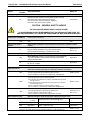 19
19
-
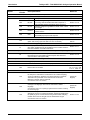 20
20
-
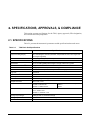 21
21
-
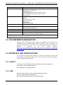 22
22
-
 23
23
-
 24
24
-
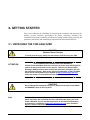 25
25
-
 26
26
-
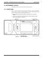 27
27
-
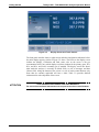 28
28
-
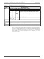 29
29
-
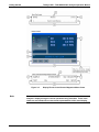 30
30
-
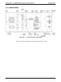 31
31
-
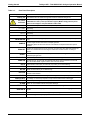 32
32
-
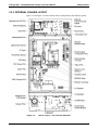 33
33
-
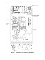 34
34
-
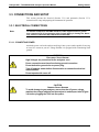 35
35
-
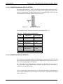 36
36
-
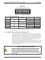 37
37
-
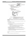 38
38
-
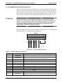 39
39
-
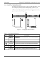 40
40
-
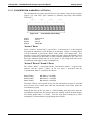 41
41
-
 42
42
-
 43
43
-
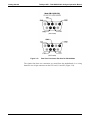 44
44
-
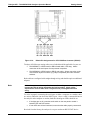 45
45
-
 46
46
-
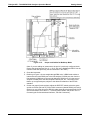 47
47
-
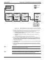 48
48
-
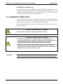 49
49
-
 50
50
-
 51
51
-
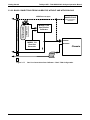 52
52
-
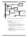 53
53
-
 54
54
-
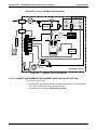 55
55
-
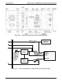 56
56
-
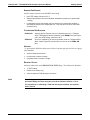 57
57
-
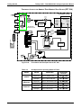 58
58
-
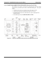 59
59
-
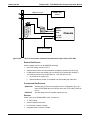 60
60
-
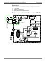 61
61
-
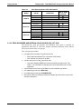 62
62
-
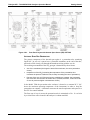 63
63
-
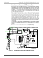 64
64
-
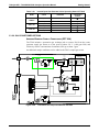 65
65
-
 66
66
-
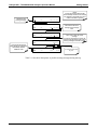 67
67
-
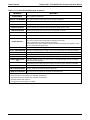 68
68
-
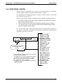 69
69
-
 70
70
-
 71
71
-
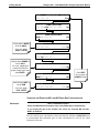 72
72
-
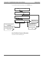 73
73
-
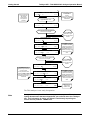 74
74
-
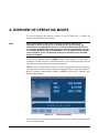 75
75
-
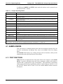 76
76
-
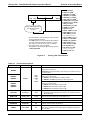 77
77
-
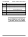 78
78
-
 79
79
-
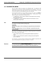 80
80
-
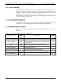 81
81
-
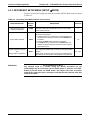 82
82
-
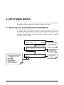 83
83
-
 84
84
-
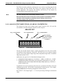 85
85
-
 86
86
-
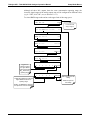 87
87
-
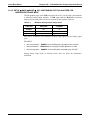 88
88
-
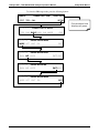 89
89
-
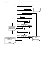 90
90
-
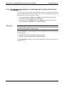 91
91
-
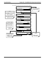 92
92
-
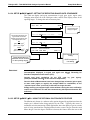 93
93
-
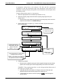 94
94
-
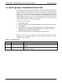 95
95
-
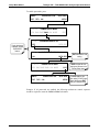 96
96
-
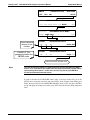 97
97
-
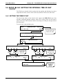 98
98
-
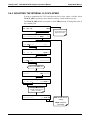 99
99
-
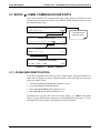 100
100
-
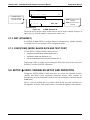 101
101
-
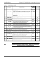 102
102
-
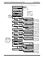 103
103
-
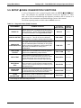 104
104
-
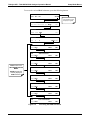 105
105
-
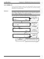 106
106
-
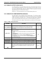 107
107
-
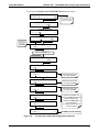 108
108
-
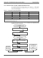 109
109
-
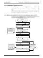 110
110
-
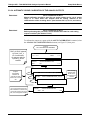 111
111
-
 112
112
-
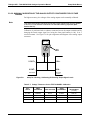 113
113
-
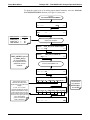 114
114
-
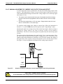 115
115
-
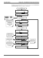 116
116
-
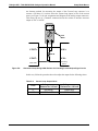 117
117
-
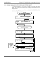 118
118
-
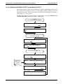 119
119
-
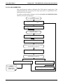 120
120
-
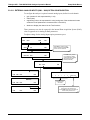 121
121
-
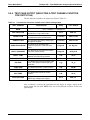 122
122
-
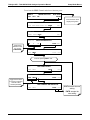 123
123
-
 124
124
-
 125
125
-
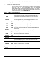 126
126
-
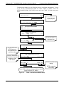 127
127
-
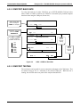 128
128
-
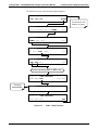 129
129
-
 130
130
-
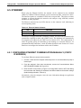 131
131
-
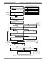 132
132
-
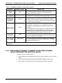 133
133
-
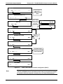 134
134
-
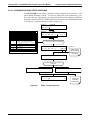 135
135
-
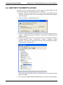 136
136
-
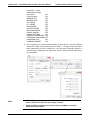 137
137
-
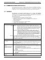 138
138
-
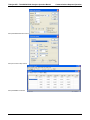 139
139
-
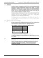 140
140
-
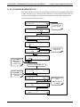 141
141
-
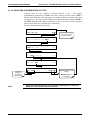 142
142
-
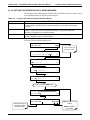 143
143
-
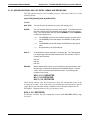 144
144
-
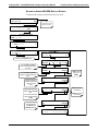 145
145
-
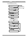 146
146
-
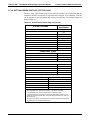 147
147
-
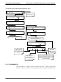 148
148
-
 149
149
-
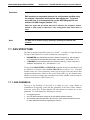 150
150
-
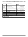 151
151
-
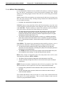 152
152
-
 153
153
-
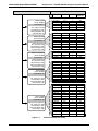 154
154
-
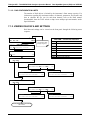 155
155
-
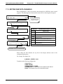 156
156
-
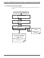 157
157
-
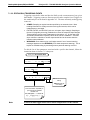 158
158
-
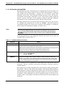 159
159
-
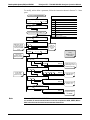 160
160
-
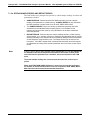 161
161
-
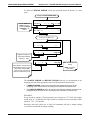 162
162
-
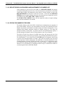 163
163
-
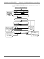 164
164
-
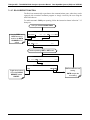 165
165
-
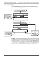 166
166
-
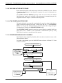 167
167
-
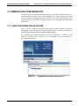 168
168
-
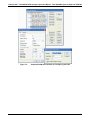 169
169
-
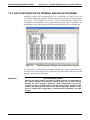 170
170
-
 171
171
-
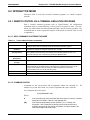 172
172
-
 173
173
-
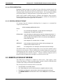 174
174
-
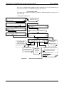 175
175
-
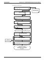 176
176
-
 177
177
-
 178
178
-
 179
179
-
 180
180
-
 181
181
-
 182
182
-
 183
183
-
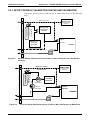 184
184
-
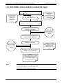 185
185
-
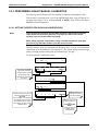 186
186
-
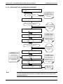 187
187
-
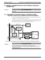 188
188
-
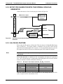 189
189
-
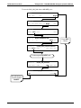 190
190
-
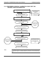 191
191
-
 192
192
-
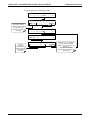 193
193
-
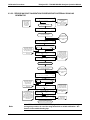 194
194
-
 195
195
-
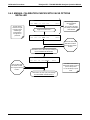 196
196
-
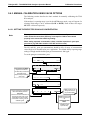 197
197
-
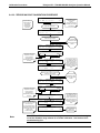 198
198
-
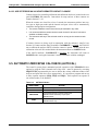 199
199
-
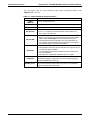 200
200
-
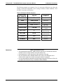 201
201
-
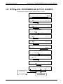 202
202
-
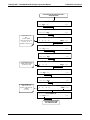 203
203
-
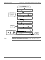 204
204
-
 205
205
-
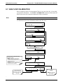 206
206
-
 207
207
-
 208
208
-
 209
209
-
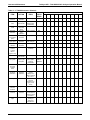 210
210
-
 211
211
-
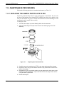 212
212
-
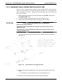 213
213
-
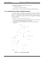 214
214
-
 215
215
-
 216
216
-
 217
217
-
 218
218
-
 219
219
-
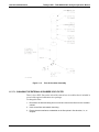 220
220
-
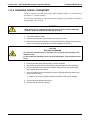 221
221
-
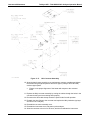 222
222
-
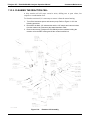 223
223
-
 224
224
-
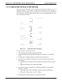 225
225
-
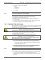 226
226
-
 227
227
-
 228
228
-
 229
229
-
 230
230
-
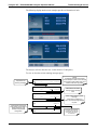 231
231
-
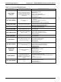 232
232
-
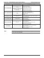 233
233
-
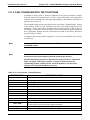 234
234
-
 235
235
-
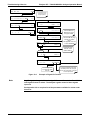 236
236
-
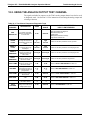 237
237
-
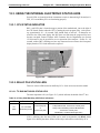 238
238
-
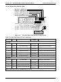 239
239
-
 240
240
-
 241
241
-
 242
242
-
 243
243
-
 244
244
-
 245
245
-
 246
246
-
 247
247
-
 248
248
-
 249
249
-
 250
250
-
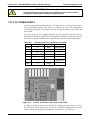 251
251
-
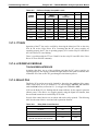 252
252
-
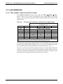 253
253
-
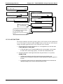 254
254
-
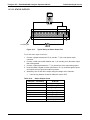 255
255
-
 256
256
-
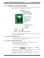 257
257
-
 258
258
-
 259
259
-
 260
260
-
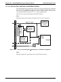 261
261
-
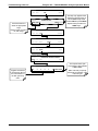 262
262
-
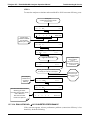 263
263
-
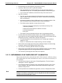 264
264
-
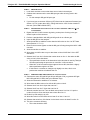 265
265
-
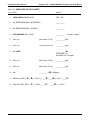 266
266
-
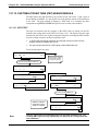 267
267
-
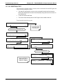 268
268
-
 269
269
-
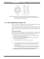 270
270
-
 271
271
-
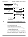 272
272
-
 273
273
-
 274
274
-
 275
275
-
 276
276
-
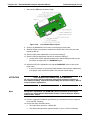 277
277
-
 278
278
-
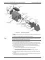 279
279
-
 280
280
-
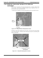 281
281
-
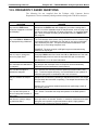 282
282
-
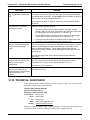 283
283
-
 284
284
-
 285
285
-
 286
286
-
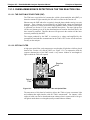 287
287
-
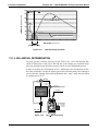 288
288
-
 289
289
-
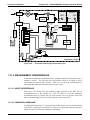 290
290
-
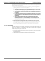 291
291
-
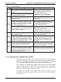 292
292
-
 293
293
-
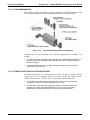 294
294
-
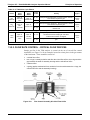 295
295
-
 296
296
-
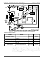 297
297
-
 298
298
-
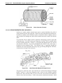 299
299
-
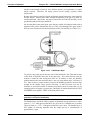 300
300
-
 301
301
-
 302
302
-
 303
303
-
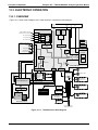 304
304
-
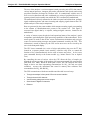 305
305
-
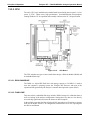 306
306
-
 307
307
-
 308
308
-
 309
309
-
 310
310
-
 311
311
-
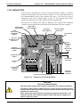 312
312
-
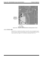 313
313
-
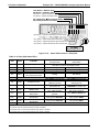 314
314
-
 315
315
-
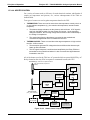 316
316
-
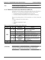 317
317
-
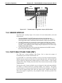 318
318
-
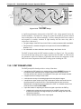 319
319
-
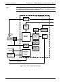 320
320
-
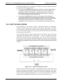 321
321
-
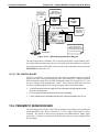 322
322
-
 323
323
-
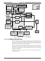 324
324
-
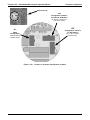 325
325
-
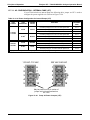 326
326
-
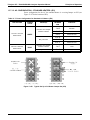 327
327
-
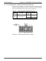 328
328
-
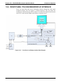 329
329
-
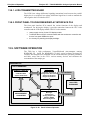 330
330
-
 331
331
-
 332
332
-
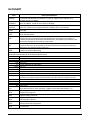 333
333
-
 334
334
-
 335
335
-
 336
336
-
 337
337
-
 338
338
-
 339
339
-
 340
340
-
 341
341
-
 342
342
-
 343
343
-
 344
344
-
 345
345
-
 346
346
-
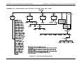 347
347
-
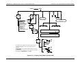 348
348
-
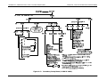 349
349
-
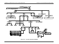 350
350
-
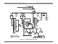 351
351
-
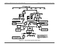 352
352
-
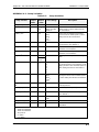 353
353
-
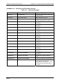 354
354
-
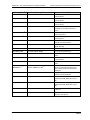 355
355
-
 356
356
-
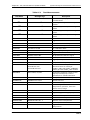 357
357
-
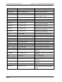 358
358
-
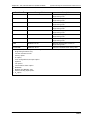 359
359
-
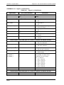 360
360
-
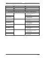 361
361
-
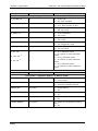 362
362
-
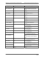 363
363
-
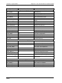 364
364
-
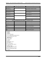 365
365
-
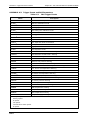 366
366
-
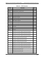 367
367
-
 368
368
-
 369
369
-
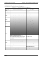 370
370
-
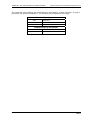 371
371
-
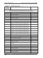 372
372
-
 373
373
-
 374
374
-
 375
375
-
 376
376
-
 377
377
-
 378
378
-
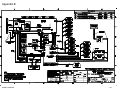 379
379


Teledyne API T200 User manual
- Category
- Measuring, testing & control
- Type
- User manual
Ask a question and I''ll find the answer in the document
Finding information in a document is now easier with AI
Related papers
-
Teledyne API T200 User manual
-
-
-
-
-
-
-
-
-
Other documents
-
 Teledyne 300 User manual
-
Samsung T200 User manual
-
Critical Environment Technologies CXT2 Operating instructions
-
Casual Home 316-84 Installation guide
-
 Teledyne 450 User manual
-
 Teledyne T200U-NOy User manual
-
 Teledyne Baby Swing T201 User manual
-
PS Audio PCA-2 User manual
-
-
 infrared industries FGA User manual


