Page is loading ...

42iQTL
Instruction Manual
Trace Level NO-NO2-NOx Analyzer
119019-00 • 15Jun2023


Thermo Scientific 42iQTL Instruction Manual iii
Contents
Introduction ........................................................................................................ 1-1
iQ Series Instrument Platform............................................................. 1-1
Principle of Operation ........................................................................ 1-3
Specifications ...................................................................................... 1-5
Dimensions ......................................................................................... 1-6
Installation and Setup ...................................................................................... 2-1
Unpacking and Inspection .................................................................. 2-1
Cover Removing and Replacing .......................................................... 2-2
Mounting Options .............................................................................. 2-3
Bench Mount ................................................................................... 2-3
Rack Mount ..................................................................................... 2-4
Setup Procedure .................................................................................. 2-6
Startup ................................................................................................ 2-9
Operation ............................................................................................................ 3-1
Instrument Display ............................................................................. 3-1
Main Menus and Keypads ................................................................ 3-5
Numeric Keypad ........................................................................... 3-6
Alphanumeric Keypad ................................................................... 3-7
Calibration .......................................................................................... 3-9
Calibrate Backgrounds ................................................................... 3-10
Calibrate NO, NOx, and Prereactor Background ........................ 3-11
Calibrate Span Coefficients ............................................................ 3-14
Calibrate NO, NO2, and NOx Span Coefficient .......................... 3-16
Zero/Span Schedule ....................................................................... 3-19
Advanced Calibration ..................................................................... 3-21
Manual Calibration ..................................................................... 3-22
Calibration History ..................................................................... 3-30
Data .................................................................................................. 3-31
View Data Log (Last Hour) ............................................................ 3-32
View Data Log (Last 24 Hours) ..................................................... 3-33
View Data Log (User Defined Time) ............................................. 3-34
Advanced Data Setup ..................................................................... 3-36
Data Logging Setup .................................................................... 3-37
Streaming Data Setup ................................................................. 3-39
Settings ............................................................................................. 3-41
Health Check ................................................................................. 3-42
Chapter 1
Chapter 2
Chapter 3

Contents
iv 42iQTL Instruction Manual Thermo Scientific
Status and Alarms........................................................................ 3-43
Predictive Diagnostics ................................................................. 3-64
Maintenance ............................................................................... 3-65
File Sharing and Support ............................................................. 3-70
iQ360 ......................................................................................... 3-71
Measurement Settings .................................................................... 3-74
Averaging Time ........................................................................... 3-75
Range Mode Selection ................................................................. 3-77
Range Settings ............................................................................. 3-79
Gas Mode ................................................................................... 3-81
Gas Units .................................................................................... 3-82
Advanced Measurement Settings ................................................. 3-83
Communications............................................................................ 3-90
Wired TCP/DHCP .................................................................... 3-92
Serial RS-232/485 ....................................................................... 3-94
Analog I/O .................................................................................. 3-95
Digital I/O .................................................................................. 3-96
Email Server (SMTP) .................................................................. 3-97
Bayern Hessen Settings ............................................................... 3-98
Ethernet Protocol Selection ......................................................... 3-99
Instrument Settings ...................................................................... 3-100
Instrument Setpoints ................................................................. 3-102
Alarm Setpoints ......................................................................... 3-103
Display Setup ............................................................................ 3-105
Clock ........................................................................................ 3-106
Time Zone ................................................................................ 3-110
Configuration .............................................................................. 3-114
Security Access Levels ................................................................... 3-115
Change Security to View Only Access ....................................... 3-117
Change Full Access Security Password ....................................... 3-118
Change Instrument Password .................................................... 3-120
Reset Instrument Password ....................................................... 3-122
USB Drive ................................................................................... 3-123
Firmware Update Via USB Drive .............................................. 3-124
Download Data To USB Drive ................................................. 3-128
Change USB Password .............................................................. 3-131
Reset USB Password .................................................................. 3-133
User Contact Information ............................................................ 3-134
Update Bootloader ....................................................................... 3-135
Calibration .......................................................................................................... 4-1
Equipment Required ........................................................................... 4-2
Zero Gas Generator.......................................................................... 4-2
Compression ................................................................................. 4-2
Drying .......................................................................................... 4-2
Oxidation ...................................................................................... 4-2
Chapter 4

Contents
Thermo Scientific 42iQTL Instruction Manual v
Scrubbing ...................................................................................... 4-3
Gas Phase Titrator............................................................................ 4-3
Flow Controllers ........................................................................... 4-3
Pressure Regulator ......................................................................... 4-3
Ozone Generator........................................................................... 4-4
Diverter Valve ............................................................................... 4-4
Reaction Chamber ........................................................................ 4-4
Mixing Chamber ........................................................................... 4-4
Output Manifold .......................................................................... 4-5
Reagents ........................................................................................... 4-5
NO Concentration Standard ......................................................... 4-5
Assaying a Working NO Standard Against a NIST-traceable NO
Standard ........................................................................................ 4-5
Zero Air ........................................................................................ 4-6
Dynamic Parameter Specifications for Gas Titrator .......................... 4-6
Determining GPT System Flow Conditions.................................. 4-7
Pre-Calibration ................................................................................... 4-8
Calibration .......................................................................................... 4-9
Connect GPT Apparatus to the Analyzer ....................................... 4-10
Adjust Instrument Gain ................................................................. 4-10
Set Backgrounds to Zero ............................................................. 4-10
Calibrate the NO Channel to the NO Calibration Gas ............... 4-12
Calibrate the NOx Channel to the NOx Calibration Gas ............. 4-12
Preparing NO, NOx, and NO2 Calibration Curves ..................... 4-13
Alternative Calibration Procedure Using NO2 Permeation Tube .... 4-15
Commercial Precision Dilution Systems...................................... 4-16
Permeation Tube System............................................................. 4-16
Commercial Permeation Systems ................................................ 4-17
Calibration in Dual Range and Auto Range Mode ............................ 4-17
Set Background Readings to Zero .................................................. 4-17
Calibrate NO Low ......................................................................... 4-18
Calibrate NOx Low ......................................................................... 4-19
Calibrate NO2 Low ........................................................................ 4-19
Calibrate NO High ........................................................................ 4-20
Calibrate NOx High ....................................................................... 4-20
Calibrate NO2 High ....................................................................... 4-21
Zero and Span Check ........................................................................ 4-21
Manual Calibration ........................................................................... 4-22
Adjust Backgrounds ....................................................................... 4-23
Adjust Span Coefficient.................................................................. 4-24
Reset Bkg to 0.000 and Span Coef to 1.000 ................................... 4-25
Zero/Span Schedule .......................................................................... 4-26
Next Time ..................................................................................... 4-26
Period ............................................................................................ 4-26
Zero/Span/Purge Duration Minutes .............................................. 4-26
Schedule Averaging Time ............................................................... 4-27

Contents
vi 42iQTL Instruction Manual Thermo Scientific
Background Calibration and Span Calibration ............................... 4-27
Zero/Span Ratio ............................................................................. 4-27
Maintenance ...................................................................................................... 5-1
Safety Precautions ............................................................................... 5-1
Fan Filter Inspection and Cleaning ..................................................... 5-1
Thermoelectric Cooler Fins Inspection and Cleaning .......................... 5-2
Capillaries Inspection and Replacement .............................................. 5-3
Pump Rebuilding ................................................................................ 5-5
Leak Test ............................................................................................ 5-8
Troubleshooting ................................................................................................. 6-1
Safety Precautions ............................................................................... 6-1
Troubleshooting Guide ....................................................................... 6-1
Servicing ............................................................................................................. 7-1
Safety Precautions ............................................................................... 7-1
Firmware Updates ............................................................................... 7-3
Replacement Parts List ........................................................................ 7-3
Fuse Replacement ............................................................................... 7-5
Filter Replacement .............................................................................. 7-6
Fan Replacement ................................................................................. 7-7
Measurement Side Removal and Replacing ......................................... 7-9
LCD Module Replacement ............................................................... 7-12
I/O Replacement ............................................................................... 7-14
Peripherals Support Board and System Controller Board
Replacement ..................................................................................... 7-16
DMC Pressure and Flow Board ........................................................ 7-17
Pump Replacement ........................................................................... 7-19
Vacuum Pump Diaphragm and Valve Replacement .......................... 7-20
Diaphragm Replacement ................................................................ 7-20
Valve Replacement ......................................................................... 7-22
Power Supply Replacement ............................................................... 7-24
Step POL Board Replacement ........................................................... 7-26
DMC PMT Cooler and Reaction Chamber Replacement ................. 7-29
PMT Cooler Shroud Removal ....................................................... 7-29
PMT Cooler Board Replacement ................................................... 7-31
Reaction Chamber Cleaning and/or Removal ................................ 7-33
Photomultiplier Tube (PMT) Replacement ................................... 7-36
DMC Converter Replacement .......................................................... 7-39
Converter Assembly Board Replacement ........................................ 7-40
Converter Cartridge Heater Replacement ....................................... 7-41
DMC Ozonator ................................................................................ 7-43
Ozonator and Transformer Removal .............................................. 7-43
Ozonator Replacement ................................................................... 7-44
Chapter 5
Chapter 6
Chapter 7

Contents
Thermo Scientific 42iQTL Instruction Manual vii
Transformer Replacement .............................................................. 7-45
Ozonator and Transformer Board Replacement ............................. 7-46
Flow Switch Replacement .............................................................. 7-47
Optional Ammonia Scrubber Replacement .................................... 7-48
Optional Manifold Replacement ....................................................... 7-50
Solenoid Valves Removal .................................................................. 7-52
System Description .......................................................................................... 8-1
Reaction Chamber DMC ................................................................. 8-2
Optical Filter ................................................................................. 8-2
Photomultiplier Tube ................................................................... 8-2
Photomultiplier Tube Cooler ........................................................ 8-2
Ozonator .......................................................................................... 8-2
Ozonator Flow Switch .................................................................. 8-2
Ozonator Permeation Dryer ................................................................ 8-3
NO2-to-NO Converter .................................................................... 8-3
Common Electronics .......................................................................... 8-3
Power Supply ................................................................................... 8-6
Front Panel ...................................................................................... 8-6
I/O and Communication Components ............................................ 8-6
System Controller Board .................................................................. 8-6
Backplane Board .............................................................................. 8-6
Peripherals Support System ................................................................. 8-7
Fan ................................................................................................... 8-7
Step POL Board ............................................................................... 8-7
External Pump ................................................................................. 8-7
Mode Solenoid ................................................................................. 8-7
Solenoid Valve Panel ........................................................................ 8-7
Flow/Pressure DMC ........................................................................... 8-7
Firmware ............................................................................................. 8-8
Optional Equipment .......................................................................................... 9-1
Connecting External Devices .............................................................. 9-1
Communication Board .................................................................... 9-2
RS-232/RS-485 Port ..................................................................... 9-2
RS-485 External Accessory Port .................................................... 9-3
Analog I/O Board ............................................................................ 9-4
Analog Voltage Inputs ................................................................... 9-4
Analog Voltage Outputs ................................................................ 9-5
Analog Output Calibration .............................................................. 9-6
Analog Output Zero Calibration ................................................... 9-7
Analog Output Full Scale Calibration ........................................... 9-9
Digital I/O Board ........................................................................... 9-11
Digital Inputs .............................................................................. 9-11
Digital Relay Switches ................................................................. 9-13
Chapter 8
Chapter 9

Contents
viii 42iQTL Instruction Manual Thermo Scientific
Valve Driver Outputs .................................................................. 9-15
Internal Zero/Span and Sample Valves .............................................. 9-17
Ammonia Scrubber ........................................................................... 9-18
NO2-to-NO Converter ..................................................................... 9-18
Permeation Dryer .............................................................................. 9-18
PTFE Particulate Filter ..................................................................... 9-18
Ozone Particulate Filter .................................................................... 9-18
Safety, Warranty, and WEEE .......................................................................... A-1
Safety .................................................................................................. A-1
Safety and Equipment Damage Alerts .............................................. A-1
Warranty ............................................................................................. A-2
WEEE Compliance ............................................................................. A-4
WEEE Symbol ................................................................................. A-4
Quick Reference ............................................................................................... B-1
List of Figures ..................................................................................... B-1
List of Tables....................................................................................... B-3
GNU Lesser General Public License ............................................................ C-1
GNU Lesser General Public License ................................................... C-1
Standards for Trace Level Analyzers ........................................................... D-1
Appendix A
Appendix B
Appendix C
Appendix D

Thermo Scientific 42iQTL Instruction Manual 1-1
Chapter 1
Introduction
The Thermo Scientific™ 42iQ Trace Level NO-NO2-NOx Analyzer utilizes
chemiluminescence technology to measure the amount of nitrogen oxides
in the air from sub-ppb levels up to 1000ppb.
The 42iQTL is a single chamber, single photomultiplier tube design that
cycles between the NO, NOx, and Zero modes. The addition of the Zero
mode provides for excellent long term stability and extremely low
minimum detectable limits.
The instrument has independent outputs for NO, NO2 and NOx and each
can be calibrated independently. Temperature and pressure correction are
standard features.
The iQ Series Instrument Platform is a smart environmental monitoring
solution for ambient and source gas analysis that affords greater control
over instrument performance and data availability.
● Distributed Measurement and Control (DMC) module design
simplifies serviceability. Each DMC module contains its own
microprocessor control enabling functional performance validation
at the module level.
● Built-in predictive diagnostics and preventive maintenance
schedules identify problems before they occur. The iQ Series
platform sends email notifications directly to Thermo Fisher
Scientific’s world class service support team or locally identified
addressees in order to proactively communicate analyzer
performance conditions and identify spare parts needs before an
operational concern arises.
● The iQ Series platform supports Modbus, streaming and VNC
protocols over serial and Ethernet as well as analog and digital I/O
for easy integration into most data management systems.
● Three standard USB ports afford convenient data download
capability as well as the ability to connect additional hardware, such
as a computer keyboard or mouse.
● The iQ Series GUI runs on a 7” color touchscreen display. The
GUI is highly flexible and can be customized to enable a tailored
iQ Series
Instrument
Platform

Introduction
iQ Series Instrument Platform
1-2 42iQTL Instruction Manual Thermo Scientific
experience to simplify daily operations. Custom designed ePort
software allows remote access to the analyzer with a PC. The ePort
control mirrors the same GUI look and feel as the instrument
touchscreen providing a speedy and familiar operational experience.
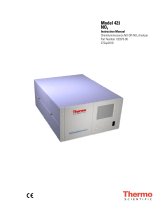
Figure 1–1. 42iQTL Front

Introduction
Principle of Operation
Thermo Scientific 42iQTL Instruction Manual 1-3
The 42iQTL operates on the principle that nitric oxide (NO) and ozone
(O3) react to produce a characteristic luminescence with an intensity
linearly proportional to the NO concentration. Infrared light emission
results when NO2 molecules decay to lower energy states. Specifically:
ν
h +
O
+
NO
O + NO 22
3→
Nitrogen dioxide (NO2) must first be transformed into NO before it can
be measured using the chemiluminescent reaction. NO2 is converted to
NO by a molybdenum NO2-to-NO converter heated to about 325 °C.
The ambient air sample is drawn into the 42iQTL through the sample
bulkhead, as shown in Figure 1–2. The sample flows through a capillary,
and then to the mode solenoid valve.
The mode solenoid valve determines whether the sample flows through the
NO2-to-NO (NOx mode) or bypasses the NO2-to-NO converter (NO
mode). The sample then flows through the converter output valve and a
flow sensor to the prereactor solenoid valve.
The prereactor solenoid valve directs the sample either to the reaction
chamber, where it mixes with ozone to give an NO reading, or to the
prereactor, where it reacts with ozone prior to the reaction chamber giving
a dynamic zero reading for the analyzer. The prereactor is sized so that
greater the 99% of a 200 ppb NO sample will react prior to entering the
reaction chamber, yet is small enough to allow other potential interferents
to pass through to the reaction chamber.
Dry air enters the 42iQTL through the permeation dryer, passes through a
flow switch, and then through a silent discharge ozonator. The ozonator
generates the ozone needed for the chemiluminescent reaction. At the
reaction chamber, the ozone reacts with the NO in the sample to produce
excited NO2 molecules. A photomultiplier tube (PMT) housed in a
thermoelectric cooler detects the luminescence generated during this
reaction.
The NO and NOx concentrations calculated in the NO and NOx modes
are stored in memory. The difference between the concentrations is used to
calculate the NO2 concentration. The 42iQTL outputs NO, NO2, and
NOx concentrations to the front panel display and the analog outputs, and
also makes the data available over the serial or Ethernet connection.
Principle of
Operation

Introduction
Principle of Operation
1-4 42iQTL Instruction Manual Thermo Scientific
Figure 1–2. 42iQTL Flow Schematic
Figure 1–3. 42iQTL Flow Schematic with Zero Span

Introduction
Specifications
Thermo Scientific 42iQTL Instruction Manual 1-5
Table 1–1 lists the specifications for the 42iQTL.
Table 1–1. 42iQTL Specifications
Range 0−1000 ppb
0−1500 µg/m3
Zero Noise
25 ppt RMS (120 second averaging time)
Detection Limit 50 ppt (120 second averaging time)
Zero Drift
Negligible
Span Drift ±1% full-scale
Response Time (in automatic
mode)
60 sec (10 second averaging time)
90 sec (60 second averaging time)
300 sec (300 second averaging time)
Linearity ±1% full-scale
Flow Rate
1 lpm
Operating Temperature Range 0–40 °C
Power Requirements
100–240 VAC 50/60 Hz
275 Watts
Physical Dimensions 24 in (D) x 16.75 in (W) x 8.72 in (H) [609 mm (D) 425.45 mm
(W) x 221.48 mm (H)]
Weight
40 lbs
Analog I/O 4 Isolated Voltage Inputs 0–10 V
6 Isolated Analog Voltages Outputs, with 4 selectable
ranges
6 Isolated Analog Current Outputs, with 2 selectable ranges
Digital I/O 16 Digital Inputs (TTL)
8 Solenoid Driver Outputs
10 Digital Reed Relay Contact Outputs
Serial Ports 1 RS-232/485 port
1 RS-485 External Accessory port
Other Ports 3 Full Speed USB ports (one in front, two in rear)
1 Gigabit Ethernet port
Communication Protocols MODBUS, Bayern Hessen, Streaming
Approvals and Certifications
CE, TUV-SUD Safety, UKCA
Specifications

Introduction
Dimensions
1-6 42iQTL Instruction Manual Thermo Scientific
Figure 1–4. Bench Mount Assembly (dimensions in inches [mm])
Dimensions

Introduction
Dimensions
Thermo Scientific 42iQTL Instruction Manual 1-7
Figure 1–5. Rack Mount Assembly (dimensions in inches [mm])

Introduction
Dimensions
1-8 42iQTL Instruction Manual Thermo Scientific
Figure 1–6. Rack Mount Requirements
Figure 1–7. Rack Requirements Part 2

Thermo Scientific 42iQTL Instruction Manual 2-1
Chapter 2
Installation and Setup
Installation and Setup describes how to unpack, setup, and start-up the
instrument. The installation should always be followed by instrument
calibration as described in the “Calibration” chapter of this manual.
Equipment Damage Do not attempt to lift the instrument by the cover or
other external fittings. ▲
The 42iQTL is shipped complete in one container. If there is obvious
damage to the shipping container when you receive the instrument, notify
the carrier immediately and hold for inspection. The carrier is responsible
for any damage incurred during shipment.
Use the following procedure to unpack and inspect the instrument.
1. Remove the instrument from the shipping container and set it on a
table or bench that allows easy access to both the front and rear.
2. Remove the cover to expose the internal components. (See “Figure 2–
1” on page 2-2.)
3. Check for possible damage during shipment.
4. Check that all connectors and circuit boards are firmly attached.
5. Re-install the cover.
6. Remove any protective plastic material from the case exterior.
Unpacking and
Inspection

Installation and Setup
Cover Removing and Replacing
2-2 42iQTL Instruction Manual Thermo Scientific
Use the following procedure to remove and replace the cover.
Equipment required:
Phillips screwdriver, #2
1. Unfasten the four 8-32 screws securing the cover (shipping screws).
2. Press in both latches located on top cover and hold while pulling up to
remove. Set upright.
Figure 2–1. Removing the Cover
3. To replace, align cover and drop in. Latches will automatically snap in
place.
Cover Removing
and Replacing

Installation and Setup
Mounting Options
Thermo Scientific 42iQTL Instruction Manual 2-3
The instrument can be installed in the following configurations:
● Bench Mount
● Rack Mount
Positioned on bench, includes installing feet. See Figure 2–2.
Equipment required:
Slot drive, 5/16-inch
1. Fasten feet in position 1 or 2 to fit to the desired depth.
Figure 2–2. Installing Feet
Mounting
Options
Bench Mount

Installation and Setup
Mounting Options
2-4 42iQTL Instruction Manual Thermo Scientific
Mounting in a rack includes removing the front panel and installing ears
and handles.
Equipment required:
Phillips drive, #2
1. Start by gripping from the top corners of the front panel and pull
outwards.
Figure 2–3. Removing the Front Panel
2. Unfasten the four 8-32 x 3/16-inch pan head screws.
3. Slide ears outwards.
4. Use the same four 8-32 x 3/16-inch pan head screws to secure it.
5. Install the handles with the four 8-32 x 3/16-inch flat head screws.
Rack Mount
/