Page is loading ...

42iQ
Instruction Manual
NO-NO2-NOx Analyzer
117435-00 • 26Jul2023


Thermo Scientific 42iQ Instruction Manual iii
Contents
Introduction ........................................................................................................ 1-1
iQ Series Instrument Platform............................................................. 1-1
Principle of Operation ........................................................................ 1-3
Specifications ...................................................................................... 1-5
Dimensions ......................................................................................... 1-7
Installation and Setup ...................................................................................... 2-1
Unpacking and Inspection .................................................................. 2-1
Cover Removing and Replacing .......................................................... 2-2
Mounting Options .............................................................................. 2-3
Bench Mount ................................................................................... 2-3
Rack Mount ..................................................................................... 2-4
Setup Procedure .................................................................................. 2-6
Startup ................................................................................................ 2-8
Operation ............................................................................................................ 3-1
Instrument Display ............................................................................. 3-1
Main Menus and Keypads ................................................................ 3-5
Numeric Keypad ........................................................................... 3-6
Alphanumeric Keypad ................................................................... 3-7
Calibration .......................................................................................... 3-9
Calibrate Backgrounds ................................................................... 3-10
Calibrate NO and NOx Background ........................................... 3-11
Calibrate Span Coefficients ............................................................ 3-13
Calibrate NO, NO2, and NOx Span Coefficient .......................... 3-15
Zero/Span Schedule ....................................................................... 3-18
Advanced Calibration ..................................................................... 3-20
Manual Calibration ..................................................................... 3-21
Calibration History ..................................................................... 3-29
Data .................................................................................................. 3-30
View Data Log (Last Hour) ............................................................ 3-31
View Data Log (Last 24 Hours) ..................................................... 3-32
View Data Log (User Defined Time) ............................................. 3-33
Advanced Data Setup ..................................................................... 3-35
Data Logging Setup .................................................................... 3-36
Select Data Logging Variables ..................................................... 3-37
Streaming Data Setup ................................................................. 3-38
Select Streaming Variables ........................................................... 3-39
Chapter 1
Chapter 2
Chapter 3

Contents
iv 42iQ Instruction Manual Thermo Scientific
Settings ............................................................................................. 3-40
Health Check ................................................................................. 3-41
Status and Alarms........................................................................ 3-42
Predictive Diagnostics ................................................................. 3-65
Maintenance ............................................................................... 3-66
Preventive Maintenance .............................................................. 3-67
Change Part ................................................................................ 3-69
Maintenance History................................................................... 3-70
File Sharing and Support ............................................................. 3-71
iQ360 ......................................................................................... 3-72
Measurement Settings .................................................................... 3-75
Averaging Time ........................................................................... 3-76
Range Mode Selection ................................................................. 3-78
Range Settings ............................................................................. 3-80
Gas Mode ................................................................................... 3-83
Gas Units .................................................................................... 3-84
Advanced Measurement Settings ................................................. 3-85
Communications............................................................................ 3-92
Wired TCP/DHCP .................................................................... 3-94
Serial RS-232/485 ....................................................................... 3-96
Analog I/O .................................................................................. 3-97
Digital I/O .................................................................................. 3-98
Email Server (SMTP) .................................................................. 3-99
Bayern Hessen Settings ............................................................. 3-100
Ethernet Protocol Selection ....................................................... 3-101
Instrument Settings ...................................................................... 3-102
Instrument Setpoints ................................................................. 3-104
Alarm Setpoints ......................................................................... 3-105
Display Setup ............................................................................ 3-107
Clock ........................................................................................ 3-108
Time Zone ................................................................................ 3-112
Configuration .............................................................................. 3-116
Security Access Levels ................................................................... 3-117
Change Security to View Only Access ....................................... 3-119
Change Full Access Security Password ....................................... 3-120
Change Instrument Password .................................................... 3-122
Reset Instrument Password ....................................................... 3-124
USB Drive ................................................................................... 3-125
Firmware Update Via USB Drive .............................................. 3-126
Download Data To USB Drive ................................................. 3-130
Change USB Password .............................................................. 3-133
Reset USB Password .................................................................. 3-135
User Contact Information ............................................................ 3-136
Update Bootloader ....................................................................... 3-137

Contents
Thermo Scientific 42iQ Instruction Manual v
Calibration .......................................................................................................... 4-1
Equipment Required ........................................................................... 4-2
Zero Gas Generator.......................................................................... 4-2
Compression ................................................................................. 4-2
Drying .......................................................................................... 4-2
Oxidation ...................................................................................... 4-2
Scrubbing ...................................................................................... 4-3
Gas Phase Titrator............................................................................ 4-3
Flow Controllers ........................................................................... 4-3
Pressure Regulator ......................................................................... 4-3
Ozone Generator........................................................................... 4-4
Diverter Valve ............................................................................... 4-4
Reaction Chamber ........................................................................ 4-4
Mixing Chamber ........................................................................... 4-4
Output Manifold .......................................................................... 4-5
Reagents ........................................................................................... 4-5
NO Concentration Standard ......................................................... 4-5
Assaying a Working NO Standard Against a NIST-traceable NO
Standard ........................................................................................ 4-5
Zero Air ........................................................................................ 4-6
Dynamic Parameter Specifications for Gas Titrator .......................... 4-6
Determining GPT System Flow Conditions.................................. 4-7
Pre-Calibration ................................................................................... 4-8
Calibration .......................................................................................... 4-9
Connect GPT Apparatus to the Analyzer ....................................... 4-10
Adjust Instrument Gain ................................................................. 4-10
Set NO and NOx Background to Zero ........................................ 4-10
Calibrate the NO Channel to the NO Calibration Gas ............... 4-12
Calibrate the NOx Channel to the NOx Calibration Gas ............. 4-12
Preparing NO, NOx, and NO2 Calibration Curves ..................... 4-13
Alternative Calibration Procedure Using NO2 Permeation Tube .... 4-15
Commercial Precision Dilution Systems...................................... 4-16
Permeation Tube System............................................................. 4-16
Commercial Permeation Systems ................................................ 4-17
Calibration in Dual Range and Auto Range Mode ............................ 4-17
Set NO and NOx Backgrounds to Zero .......................................... 4-17
Calibrate NO Low ......................................................................... 4-18
Calibrate NOx Low ......................................................................... 4-19
Calibrate NO2 Low ........................................................................ 4-19
Calibrate NO High ........................................................................ 4-20
Calibrate NOx High ....................................................................... 4-20
Calibrate NO2 High ....................................................................... 4-21
Zero and Span Check ........................................................................ 4-21
Manual Calibration ........................................................................... 4-22
Chapter 4

Contents
vi 42iQ Instruction Manual Thermo Scientific
Adjust NO and NOx Backgrounds ................................................. 4-23
Adjust Span Coefficient.................................................................. 4-24
Reset Bkg to 0.000 and Span Coef to 1.000 ................................... 4-25
Zero/Span Schedule .......................................................................... 4-26
Next Time ..................................................................................... 4-26
Period ............................................................................................ 4-26
Zero/Span/Purge Duration Minutes .............................................. 4-26
Schedule Averaging Time ............................................................... 4-27
Background Calibration and Span Calibration ............................... 4-27
Zero/Span Ratio ............................................................................. 4-27
References ......................................................................................... 4-27
Maintenance ...................................................................................................... 5-1
Safety Precautions ............................................................................... 5-1
Fan Filter Inspection and Cleaning ..................................................... 5-1
Thermoelectric Cooler Fins Inspection and Cleaning .......................... 5-2
Capillaries Inspection and Replacement .............................................. 5-3
Pump Rebuilding ................................................................................ 5-5
Leak Test ............................................................................................ 5-9
Troubleshooting ................................................................................................. 6-1
Safety Precautions ............................................................................... 6-1
Troubleshooting Guide ....................................................................... 6-1
Servicing ............................................................................................................. 7-1
Safety Precautions ............................................................................... 7-1
Firmware Updates ............................................................................... 7-3
Replacement Parts List ........................................................................ 7-3
Fuse Replacement ............................................................................... 7-5
Filter Replacement .............................................................................. 7-6
Fan Replacement ................................................................................. 7-7
Measurement Side Removal and Replacing ......................................... 7-9
LCD Module Replacement ............................................................... 7-12
I/O Replacement ............................................................................... 7-14
Peripherals Support Board and System Controller Board
Replacement ..................................................................................... 7-16
DMC Pressure and Flow Board ........................................................ 7-17
Pump Replacement ........................................................................... 7-19
Capillary Cleaning and/or Replacement ............................................ 7-21
Capillary O-Ring Replacement ......................................................... 7-23
Power Supply Replacement ............................................................... 7-23
Step POL Board Replacement ........................................................... 7-25
DMC PMT Cooler and Reaction Chamber Replacement ................. 7-28
PMT Cooler Shroud Removal ....................................................... 7-28
PMT Cooler Board Replacement ................................................... 7-30
Chapter 5
Chapter 6
Chapter 7

Contents
Thermo Scientific 42iQ Instruction Manual vii
Reaction Chamber Cleaning and/or Removal ................................ 7-32
Photomultiplier Tube (PMT) Replacement ................................... 7-35
DMC Converter Replacement .......................................................... 7-38
Converter Assembly Board Replacement ........................................ 7-39
Converter Cartridge Heater Replacement ....................................... 7-40
DMC Ozonator ................................................................................ 7-42
Ozonator and Transformer Removal .............................................. 7-42
Ozonator Replacement ................................................................... 7-43
Transformer Replacement .............................................................. 7-44
Ozonator and Transformer Board Replacement ............................. 7-45
Flow Switch Replacement .............................................................. 7-46
Optional Ammonia Scrubber Replacement .................................... 7-47
Optional Manifold Replacement ....................................................... 7-49
Optional Solenoid Valves Removal ................................................... 7-51
Permeation Oven Replacement ......................................................... 7-53
Permeation Oven Board Replacement ............................................... 7-56
System Description .......................................................................................... 8-1
Reaction Chamber DMC ................................................................. 8-2
Optical Filter ................................................................................. 8-2
Photomultiplier Tube ................................................................... 8-2
Photomultiplier Tube Cooler ........................................................ 8-2
Ozonator .......................................................................................... 8-2
Ozonator Flow Switch .................................................................. 8-2
Ozonator Permeation Dryer ................................................................ 8-3
NO2-to-NO Converter .................................................................... 8-3
Permeation Oven (Optional) .............................................................. 8-3
Common Electronics .......................................................................... 8-3
Power Supply ................................................................................... 8-6
Front Panel ...................................................................................... 8-6
I/O and Communication Components ............................................ 8-6
System Controller Board .................................................................. 8-6
Backplane Board .............................................................................. 8-6
Peripherals Support System ................................................................. 8-7
Fan ................................................................................................... 8-7
Step POL Board ............................................................................... 8-7
Sample Pump ................................................................................... 8-7
Mode Solenoid ................................................................................. 8-7
Solenoid Valve Panel ........................................................................ 8-7
Flow/Pressure DMC ........................................................................... 8-7
Firmware ............................................................................................. 8-8
Optional Equipment .......................................................................................... 9-1
Connecting External Devices .............................................................. 9-1
Communication Board .................................................................... 9-2
Chapter 8
Chapter 9

Contents
viii 42iQ Instruction Manual Thermo Scientific
RS-232/RS-485 Port ..................................................................... 9-2
RS-485 External Accessory Port .................................................... 9-3
Analog I/O Board ............................................................................ 9-4
Analog Voltage Inputs ................................................................... 9-4
Analog Voltage Outputs ................................................................ 9-5
Analog Output Calibration .............................................................. 9-6
Analog Output Zero Calibration ................................................... 9-7
Analog Output Full Scale Calibration ........................................... 9-9
Digital I/O Board ........................................................................... 9-11
Digital Inputs .............................................................................. 9-11
Digital Relay Switches ................................................................. 9-13
Valve Driver Outputs .................................................................. 9-15
Internal Zero/Span and Sample Valves .............................................. 9-17
Lag Volume ...................................................................................... 9-18
Principle of Operation ................................................................... 9-18
Lag Volume Test ............................................................................ 9-19
Ammonia Scrubber ........................................................................... 9-20
NO2-to-NO Converter ..................................................................... 9-20
Sample Permeation Dryer ................................................................. 9-20
Internal Permeation Span Source ...................................................... 9-20
Permeation Tube Installation ......................................................... 9-22
Computation of Concentrations .................................................... 9-25
PTFE Particulate Filter ..................................................................... 9-26
Ozone Particulate Filter .................................................................... 9-26
Safety, Warranty, and WEEE .......................................................................... A-1
Safety .................................................................................................. A-1
Safety and Equipment Damage Alerts .............................................. A-1
Warranty ............................................................................................. A-2
WEEE Compliance ............................................................................. A-4
WEEE Symbol ................................................................................. A-4
Quick Reference ............................................................................................... B-1
List of Figures ..................................................................................... B-1
List of Tables....................................................................................... B-3
GNU Lesser General Public License ............................................................ C-1
GNU Lesser General Public License ................................................... C-1
Appendix A
Appendix B
Appendix C

Thermo Scientific 42iQ Instruction Manual 1-1
Chapter 1
Introduction
The Thermo Scientific™ 42iQ NO-NO2-NOx Analyzer utilizes
chemiluminescence technology to measure the amount of nitrogen oxides
in the air from sub-ppb levels up to 100 ppm.
This analyzer is a single chamber, single photomultiplier tube design that
cycles between the NO and NOx modes.
The 42iQ Analyzer has independent outputs for NO, NO2 and NOx that
can be calibrated separately. If required, the instrument can be operated
continuously in either the NO or NOx modes allowing for response times
of less than five seconds. Dual range, auto range, temperature correction
and pressure correction are standard features.
The iQ Series Instrument Platform is a smart environmental monitoring
solution for ambient and source gas analysis that affords greater control
over instrument performance and data availability.
● Distributed Measurement and Control (DMC) module design
simplifies serviceability. Each DMC module contains its own
microprocessor control enabling functional performance validation
at the module level.
● Built-in predictive diagnostics and preventive maintenance
schedules identify problems before they occur. The iQ Series
platform sends email notifications directly to Thermo Fisher
Scientific’s world class service support team or locally identified
addressees in order to proactively communicate analyzer
performance conditions and identify spare parts needs before an
operational concern arises.
● The iQ Series platform supports Modbus, streaming and VNC
protocols over serial and Ethernet as well as analog and digital I/O
for easy integration into most data management systems.
● Three standard USB ports afford convenient data download
capability as well as the ability to connect additional hardware, such
as a computer keyboard or mouse.
● The iQ Series GUI runs on a 7” color touchscreen display. The
GUI is highly flexible and can be customized to enable a tailored
iQ Series
Instrument
Platform

Introduction
iQ Series Instrument Platform
1-2 42iQ Instruction Manual Thermo Scientific
experience to simplify daily operations. Custom designed ePort
software allows remote access to the analyzer with a PC. The ePort
control mirrors the same GUI look and feel as the instrument
touchscreen providing a speedy and familiar operational experience.
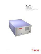
Figure 1–1. 42iQ Front

Introduction
Principle of Operation
Thermo Scientific 42iQ Instruction Manual 1-3
The 42iQ operates on the principle that nitric oxide (NO) and ozone (O3)
react to produce a characteristic luminescence with an intensity linearly
proportional to the NO concentration. Infrared light emission results when
NO2 molecules decay to lower energy states. Specifically:
ν
h +
O
+
NO
O + NO
22
3
→
Nitrogen dioxide (NO2) must first be transformed into NO before it can
be measured using the chemiluminescent reaction. NO2 is converted to
NO by a molybdenum NO2-to-NO converter heated to about 325 °C (the
optional stainless steel converter is heated to 625 °C).
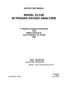
The ambient air sample is drawn into the 42iQ through the sample
bulkhead, as shown in Figure 1–2. The sample flows through a capillary,
and then to the mode solenoid valve. The solenoid valve routes the sample
either straight to the reaction chamber (NO mode) or through the NO2-to-
NO converter and then to the reaction chamber (NOx mode). The reaction
chamber pressure is measured to infer the sample flow. Pressure deviations
outside of the acceptable range are reported as a fault.
Dry air enters the 42iQ through the permeation dryer, passes through a
flow switch, and then through a silent discharge ozonator. The ozonator
generates the ozone needed for the chemiluminescent reaction. At the
reaction chamber, the ozone reacts with the NO in the sample to produce
excited NO2 molecules. A photomultiplier tube (PMT) housed in a
thermoelectric cooler detects the luminescence generated during this
reaction. From the reaction chamber, the exhaust travels through the ozone
(O3) converter to the pump, and is released through the vent.
The NO and NOx concentrations calculated in the NO and NOx modes
are stored in memory. The difference between the concentrations is used to
calculate the NO2 concentration. The 42iQ outputs NO, NO2, and NOx
concentrations to the front panel display and the analog outputs, and also
makes the data available over the serial or Ethernet connection.
Principle of
Operation

Introduction
Principle of Operation
1-4 42iQ Instruction Manual Thermo Scientific
Figure 1–2. 42iQ Flow Schematic
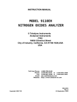
Figure 1–3. 42iQ Flow Schematic with Zero Span

Introduction
Specifications
Thermo Scientific 42iQ Instruction Manual 1-5
Table 1–1 lists the specifications for the 42iQ.
Table 1–1. 42iQ Specifications
Range 0−20 ppm
0−30 mg/m3
Extended Ranges 0−100 ppm
0
−
150 mg/m
3
Zero Noise 0.20 ppb RMS (60 second averaging time)
Detection Limit
0.40 ppb (60 second averaging time)
Zero Drift <0.40 ppb (24 hour)
Span Drift
±
1% full-scale (1 week)
Response Time 40 sec (10 second averaging time)
80 sec (60 second averaging time)
300 sec (300 second averaging time)
Linearity
±
1% full-scale
Flow Rate 0.6−0.8 lpm
Operating Temperature Range
0–
40 °
C
Power Requirements
100–240 VAC 50/60 Hz
275 Watts
Physical Dimensions 24 in (D) x 16.75 in (W) x 8.72 in (H) [609 mm (D) 425.45 mm
(W) x 221.48 mm (H)]
Weight 40 lbs
Analog I/O 4 Isolated Voltage Inputs 0–10 V
6 Isolated Analog Voltages Outputs, with 4 selectable
ranges
6 Isolated Analog Current Outputs, with 2 selectable ranges
Digital I/O 16 Digital Inputs (TTL)
8 Solenoid Driver Outputs
10 Digital Reed Relay Contact Outputs
Serial Ports 1 RS-232/485 port
1 RS-485 External Accessory port
Other Ports 3 Full Speed USB ports (one in front, two in rear)
1 Gigabit Ethernet port
Communication Protocols
MODBUS, Streaming, Bayern Hessen
Approvals and Certifications CE, TUV-SUD Safety, EPA, UKCA
Specifications

Introduction
Specifications
1-6 42iQ Instruction Manual Thermo Scientific
Table 1–2. 42iQ Optional Permeation Oven Specifications
Temperature Control Three user selectable set points: 30, 35, 45 °C
Temperature Stability ± 0.1 °C
Warm-up Time 1 hour (permeation device can take 24 to 48 hours to stabilize)
Carrier Gas Flow ≈ 700 scc/min
Chamber size Accepts permeation tubes up to 9 cm in total length; 1 cm in
diameter
Physical Dimensions Contained inside the 42iQ
Power Requirements
24 VDC, 50 watts (in addition to the standard 42iQ)
Weight Approximately five pounds (in addition to standard 42iQ)

Introduction
Dimensions
Thermo Scientific 42iQ Instruction Manual 1-7
Figure 1–4. Bench Mount Assembly (dimensions in inches [mm])
Dimensions

Introduction
Dimensions
1-8 42iQ Instruction Manual Thermo Scientific
Figure 1–5. Rack Mount Assembly (dimensions in inches [mm])

Introduction
Dimensions
Thermo Scientific 42iQ Instruction Manual 1-9
Figure 1–6. Rack Mount Requirements
Figure 1–7. Rack Requirements Part 2


Thermo Scientific 42iQ Instruction Manual 2-1
Chapter 2
Installation and Setup
Installation and Setup describes how to unpack, setup, and start-up the
instrument. The installation should always be followed by instrument
calibration as described in the “Calibration” chapter of this manual.
Equipment Damage Do not attempt to lift the instrument by the cover or
other external fittings. ▲
The 42iQ is shipped complete in one container. If there is obvious damage
to the shipping container when you receive the instrument, notify the
carrier immediately and hold for inspection. The carrier is responsible for
any damage incurred during shipment.
Use the following procedure to unpack and inspect the instrument.
1. Remove the instrument from the shipping container and set it on a
table or bench that allows easy access to both the front and rear.
2. Remove the cover to expose the internal components. (See “Figure 2–
1” on page 2-2.)
3. Check for possible damage during shipment.
4. Check that all connectors and circuit boards are firmly attached.
5. Re-install the cover.
6. Remove any protective plastic material from the case exterior.
Unpacking and
Inspection

Installation and Setup
Cover Removing and Replacing
2-2 42iQ Instruction Manual Thermo Scientific
Use the following procedure to remove and replace the cover.
Equipment required:
Phillips screwdriver, #2
1. Unfasten the four 8-32 screws securing the cover (shipping screws).
2. Press in both latches located on top cover and hold while pulling up to
remove. Set upright.
Figure 2–1. Removing the Cover
3. To replace, align cover and drop in. Latches will automatically snap in
place.
Cover Removing
and Replacing
/