Page is loading ...

Doc. Ref No.: mttB/om/101
Issue No.:07
TT7S Series
INDEX
F
EATURES
..........................................................................................................................................................
1
A
PPLICATION
...................................................................................................................................................
1
S
PECIFICATIONS
..............................................................................................................................................
2
D
IMENSIONS
......................................................................................................................................................
2
S
AFETY AND WARNING
.................................................................................................................................
3
C
ONFIGURATION AND CONNECTION
........................................................................................................
3
I
NSTALLATION
...................................................................................................................................................
4
A
CCESSORIES
..................................................................................................................................................
4
O
RDERING CODE
.............................................................................................................................................
4
T
ROUBLE SHOOTING
......................................................................................................................................
4

Doc. Ref No.:mttB/om/101
Issue No.:07
1 | P a g e
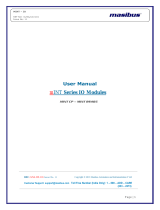
TT7S Series
• TT7S10-H: Loop Powered Head Mount
• TT7S10 : Loop Powered DIN Rail Mount
• TT7S11S : Aux Powered DIN Rail Mount
Isolated. Universal. Accurate
F
EATURES
• Universal input (RTD, Thermocouple, Ohm, mV)
• 1.5 KVAC Isolation between I/P & O/P
• Linearized Output
• Highly Accurate
• Fully Programmable for Input type & Range
• Fast Response time: <500 ms
• Digital Filter
• Windows mTRAN software for Configuration,
Calibration & Monitoring
• Reverse polarity protection
• Direct/Reverse output
• Sensor break detection
• Loop/Aux Powered models
• Extended Power Supply Range of 20 to
265VDC/AC for Aux Power Transmitter TT7S11S
A
PPLICATION
• Power Plants
• Metal Industry
• Oil & Gas
• Chemical
• Glass Industry
• Cement
• Fertilizer
TT7S series Transmitters are designed for Isolated and accurate
Temperature measurements and signal conditioning Applications.
Model TT7S10-H is 2 Wire Loop powered Head Mount Transmitter,
Model TT7S10 is 2-wire Loop powered Din Rail Mount Transmitter
and Model TT7S11S is 4-wire Auxiliary powered Transmitter.
All models are programmable for Thermocouples, Pt-100 RTD, mV
and Resistance/Potentiometer. Output signal is standard 4-20mA in
2-wire & mA or Volts in 4-wire. Programming of the Transmitters is
easy by means of user friendly mTRAN windows based
configuration software.
Isolated & Programmable Temperature
Transmitter
TT7S10-H
TT7S10
TT7S11S

Doc. Ref No.:mttB/om/101
Issue No.:07
2 | P a g e
TT7S Series
1. Dimensions
1.1 TT7S10-H
1.2 TT7S10& TT7S11S
93.5
85.7
5
114.7
72.9
59.3
77.7
99.7
34.65
10.12
56.1
S
PECIFICATION
I
nput
RTD Pt100 3-Wire (3/4 Wire in TT7S11S)
Resistance/Potentiometer 0-2500Ω
Sensor current ~0.2mA
Thermocouple E, J, K,T,B,R,S,N (ANSI standard) (See: Table 1)
mV 0-75mV/ 0-500mV DC
Input Impedance > 1M ohms
Sensor burn out current <1 uA
Input Sensor Range Refer Table 1
Zero & Span Adjust Through mTRAN Software
Accuracy
E, J, K, T, N, PT-100/ mV, Ω 0.1% of FS± 1 Deg/count
B, R, S 0.25% of FS± 1 Deg
CJC Error
E, J, K, T, N ±2 ºC
B, R, S ±3 ºC
Stability ±0.1% per year
Response time < 500msec
Digital Filter 0-20 sec settable through software, (2 sec default)
CMRR > 120 dB
NMRR ≈ 40 dB
Temperature co-efficient <150ppm
Output
TT7S10 & TT7S10-H
Output 4-20mA or 20-4mA (User Selectable)
Resolution 1 uA
Sensor break Output Lo < 3.4 mA or Hi >20.8 (User Selectable)
Output load
R load= (Voltage supply - 8.5)/0.021 Ohm (TT7S10
and TT7S10-H)
TT7S11S
Output 0/4-20mA, 0/1-5V, 0/2-10V (User Selectable)
Output Direction Direct / Reverse (User Selectable)
Resolution Current
Voltage 1 uA
0.25 mV (0/1-5V), 0.5mV(0/2-10V)
Sensor break Output Lo < 3.4mA or Hi >20.8mA (user set)
Output Load
mA: Load Voltage ≤ 15V
(e.g. for 4-20mA: 15V/20mA ≤ 750Ω)
V: Load Current ≤ 1.25 mA
(e.g. for 0-5V: 5V/1.25mA ≥ 4 KΩ)
Supply
TT7S10 & TT7S10-H 8.5-36 VDC 2-Wire
TT7S11S 20-265V DC/AC (45-65Hz) <3VA
Isolation
TT7S10 & TT7S10
-
H
1.5KVAC Galvanic for 1 minute between I/P & O/P
TT7S11S
Input /Output/Supply 1.5KVAC Galvanic for 1 minute between all ports
Physical
Mounting
TT7S10 & TT7S11S 35 mm DIN Rail
TT7S10-H Sensor Head (35 mm DIN Rail-Optional Accessory)
Dimensions
TT7S10 & TT7S11S 12.5(W)x99(H)x114.5(D) mm
TT7S10-H Diameter(46mm) x Height(28mm)
Enclosure Material
TT7S10-H Polycarbonate
TT7S10 & TT7S11S Polyamide
Environmental
Operating temperature
TT7S10-H -40 to 85 °C
TT7S10 -40 to 55 °C
TT7S11S 0 to 55 °C
Storage temperature -20 to +85 °C
Humidity 30 to 95% (Non-condensing)
Terminal
Detail
Terminal Block UL,CSA standard & CE certified
Terminal Cable Size 2.5mm²
All dimensions are in mm.

Doc. Ref No.:mttB/om/101
Issue No.:07
3 | P a g e
TT7S Series
Input Type Span Adjustment
0-2500 ohms
> 1K ohms (1uA Resolution)
>200 ohms (5uA Resolution)
>400 ohms (5uA Resolution)
0-75mV >30mV (1uA Resolution)
>10mV (5uA Resolution)
0-500 mV >200mV (1uA Resolution)
>50mV (5uA Resolution)
S
AFETY AND WARNING
To avoid Electrostatic Discharge (ESD) to the
transmitter, which may cause permanent damage,
always ground yourself by touching some ground
equipment before configuring the transmitter.
Before installation or beginning of any troubleshooting
procedures the power to all equipment must be switched
off and isolated. Units suspected of being faulty must be
disconnected and removed first and brought to a
properly equipped workshop for testing and repair.
Component replacement and interval adjustments must
be made by a company person only. Wiring must be
carried out by personnel, who have basic electrical
knowledge and practical experience.
All wiring must confirm to appropriate standards of good
practice and local codes and regulations. Wiring must
be suitable for voltage, current, and temperature rating
of the system. Beware not to over-tighten the terminal
screws.
C
ONFIGURATION AND CONNECTION
TT7S series transmitters are configurable through
configuration software “mTRAN".
Configuration and calibration should be done in
nonhazardous area.
Once configuration is done, parameters are
changed.
Connection details:
TT7S10-H
Terminal 3, 4 & 5: For RTD/Potentiometer Input
Terminal 4 & 5: For T/C & Linear Input
Terminal 1 & 2: For Loop Power and Output
TT7S10
Terminal 3, 4 & 5: For RTD/Potentiometer Input
Terminal 3 & 4: For T/C & Linear Input
Terminal 1 & 2: For Loop Power and Output
TT7S11S
Terminal 1, 2, 3 & 4: For RTD/Potentiometer Input
Terminal 2 & 4: For T/C & Linear Input
Terminal 7 & 8: Power Supply Input
Terminal 5 & 6: For Output
Table1: Input Sensor Range
Input Type Ranges
E -200 to 1000ºC
J -200 to 1200ºC
K -200 to 1370ºC
T -200 to 400ºC
B 450 to 1800ºC
R 0 to 1750ºC
S 0 to 1750ºC
N -200 to 1300ºC
Pt-100 -200 to 850ºC
LINEAR 0-75mV/ 0-500mV
Potentiometer 0-2500Ω

Doc. Ref No.:mttB/om/101
Issue No.:07
4 | P a g e
TT7S Series
I
NSTALLATION
Din Rail Mounting:
The unit can be snapped onto all DIN rails (35mm)
According to EN60715. The device must be
mounted horizontally (Supply terminal blocks
facing upper wards)
The housing is mounted on the DIN rail by
swiveling it into place. Adequate Air circulation
must be considered between each Aux Powered
devices to maintain their Operating temperature
ranges, by keeping some space between each
devices.
Removal:
Release the Snap-On catch using a screwdriver
and then detach the module from the bottom
edge of the DIN Rail.
Head Mounting:
The Unit can be mounted with 2 screws given with
the sensor head as shown in figure with screw
driver.
TT7S1
0
,
TT7S1
1S
TT7S10
-
H
A
CCESSORIES
Mounting Kit
Head Mounting: m-MK-FH-00-1 (Only
For TT7S10-H)
Rail Mounting Kit: m-MK-RC-10-1
(Only for TT7S10-H)
Cable Accessories
S
r.
No.
Description of
Accessories
Part No.
Qty
1 Configuration cable
For TT7S10,TT7S10-H
& TT7S11S
m-cb-5-4-7-10-0-0-1-1 01
O
RDERING
C
ODE
Model
Transmitter Type
Input
Type
Output
TT7S 10 Loop-Powered
Din Rail Mount 1 E 1 4-20mA
11S Aux-Powered Din
Rail Mount 2 J 2* 0-20mA
10-H Loop-Powered
Head Mount 3 K 3* 1-5V
4 T 4* 0-10V
5 B 5* 0-5V
6 R 6* 2-10V
7 S
8 N
9 Pt-100
U 0-75mV
H 0-500mV
I 0-2500Ω
*Available in Aux Powered model TT7S11S Only
T
ROUBLE
S
HOOTING
Unit Not Turning ON?
TT7S10&TT7S10-H - If transmitter is not
delivering loop current, check the circuit from
Power supply, two wire transmitter & receiving
device. If still transmitter is not delivering loop
current, check the supply connections and polarity
of 24Vdc terminals.
TT7S11S
- If RED LED at the front side is not
turned “ON”, the device is not getting sufficient
supply or the connections are not as per terminal
details.
Output not matching with expected value?
Make sure the load on output of device is as per
specification criteria.
Communication with PC is not proper (for all
models)
The reason can be in pc driver is not installed,
Comport is not proper selected, Or connection
from PC to unit is loose.
masibus
Automation & Instrumentation Pvt. Ltd.
B/30, GIDC Electronics Estate, Sector- 25,
Gandhinagar-382044, Gujarat, India
Ph: 91-079-23287275 / 76 / 77 / 78 / 79
Fax: 91-079-23287281/ 82
Email: supp[email protected]om
Web: www.masibus.com
/