Watlow PPC-2000 User guide
- Category
- Digital & analog I/O modules
- Type
- User guide

PPC-2000
User’s Guide
WATLOW
1241 Bundy Boulevard
Winona, Minnesota USA 55987
Phone: +1 (507) 454-5300,
Fax: +1 (507) 452-4507
Part No. 0600-3000-2000 Rev 2.3d
http://www.watlow.com


Adaptive Addendum PPC-2000 User's Guide
0600-0049-0001 rev C Watlow Anafaze 1
PPC-2000 Adaptive Control
Addendum
Scope
This document describes the additional features and functionality found
in the PPC-2010-xxB with adaptive control. Refer to the PPC-2000
User’s Guide regarding all other functionality which is the same as the
standard version.
Introduction
The Watlow Anafaze PPC-2000 controller offers these standard options:
• Forty-eight loops of conventional PID control with auto-tuning
capability
-or-
• Eight loops of adaptive control plus 24 loops of conventional PID
control with auto-tuning for a total of 32 loops (the option described
in this document)
ANAWIN3 HMI software is available to support either option. A mix of
these options is not supported by ANAWIN3.
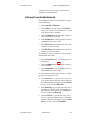
ANAWIN3 Software Installation
Follow the standard instructions to install and setup ANAWIN3. In the
setup program select the Adaptive Control option.
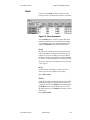
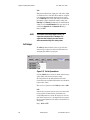
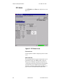
Spreadsheet Overview Screen
Several new parameters and options appear on the Spreadsheet Overview
screen in support of the adaptive control option. These parameters and
options are applicable only for the first eight channels and are omitted or
ignored for channels 9 to 32.
Control Type
An additional option appears for Control Type. Select Adaptive to enable
adaptive control and tuning on a channel. This option is only valid for
channels 1 to 8.
Values: PID1 (0), PID2 (1), Adaptive (2) and Retransmit (3)
Default: PID1 (0)
Modbus Address (Channels 1 to 32): 46401 to 46432
Parameter Number: 19
LogicPro Driver: Database
LogicPro Address (Channels 1 to 32): 19.1 to 19.32

Adaptive Addendum PPC-2000 User's Guide
0600-0049-0001 rev C Watlow Anafaze 2
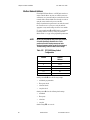
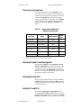
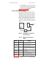
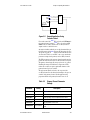
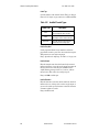
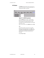
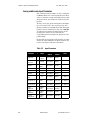
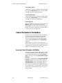
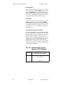
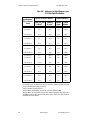
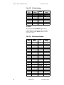
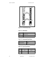
Adaptive Mode
When Control Type is set to Adaptive, this parameter can be used to
pause tuning or to reset the adaptive algorithm and have it relearn the
system. This parameter has no effect on control if the Control Type for
the loop is set to an option other than Adaptive.
Values: Adapt (0), Reset (1) and Hold (2)
Default: Reset (1)
Modbus Address (Channels 1 to 32): 49001 to 49032
Parameter Number: 21
LogicPro Driver: Database
LogicPro Address (Channels 1 to 32): 21.1 to 21.32
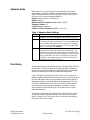
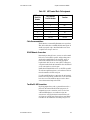
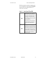
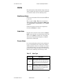
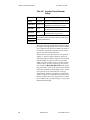
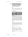
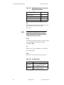
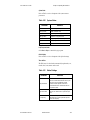
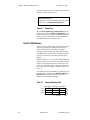
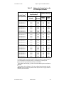
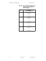
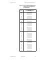
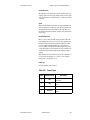
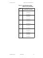
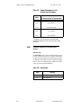
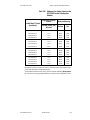
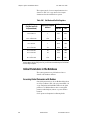
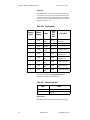
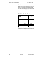
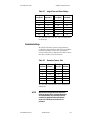
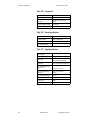
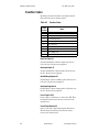
Table 1. Adaptive Mode Settings
Setting Description
Adapt The normal setting for a loop with Control Type set to
Adaptive. The loop is adapting and tuning while controlling.
Reset Select this option to have the control loop start from scratch
and relearn the load characteristics. The Control Mode must
be set to Off or Manual to select this option for an adaptive
loop. This is the normal setting for a loop with Control Type
set to a value other than Adaptive.
Hold Select this option to have the control loop stop learning
temporarily but retain the learned load characteristics. For
example in the event that maintenance will be performed, it
may be advantageous to pause adapting to avoid false data
being introduced. Select this option anytime you want the
controller to stop adapting and continue to control with the
parameters learned up to that point.
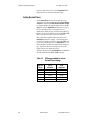
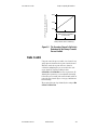
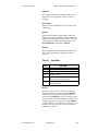
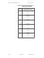
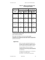
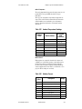
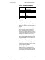
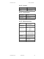
Plant Delay
This parameter indicates the amount of delay in seconds in the load. This
characteristic of the load or plant has a significant impact on adaptive
control. A larger number indicates a longer delay between, for example
an increase in heater power and an increase in the temperature.
Choose Automatic and then set the Control Mode to Auto to have the
adaptive algorithm determine the plant delay for the loop. The loop must
be at least 40 degrees below set point and the controller must observe a
temperature change of at least 20 degrees to determine the Plant Delay.
If you have determined the Plant Delay with the PPC-2000's adaptive
control previously and found the performance acceptable, you may
choose the delay directly and the loop will use the value you choose
rather than measure it.
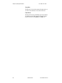
This setting is not reset by the Adaptive Mode parameter's Reset option.
To have the controller relearn the Plant Delay, set the loop's Control
Mode to Manual or Off, set the Plant Delay to Automatic, and then set
the Control Mode to Auto again.

Adaptive Addendum PPC-2000 User's Guide
0600-0049-0001 rev C Watlow Anafaze 3
This parameter has no effect on control if the Control Type for the loop is
set to an option other than Adaptive.
Values: Automatic (0) and 1 (1) to 600 seconds (600)
Default: Automatic (0)
Modbus Address (Channels 1 to 32): 49051 to 49082
Parameter Number: 28
LogicPro Driver: Database
LogicPro Address (Channels 1 to 32): 28.1 to 28.32
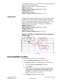
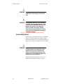
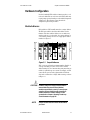
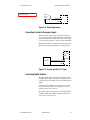
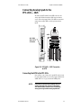
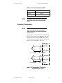
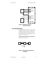
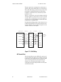
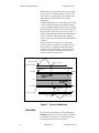
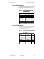
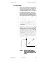
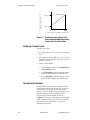
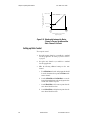
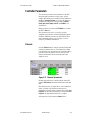
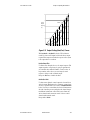
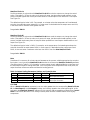
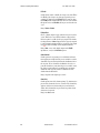
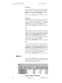
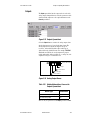
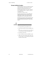
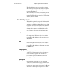
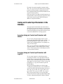
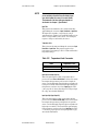
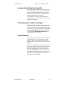
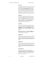
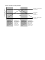
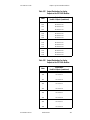
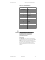
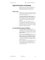
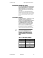
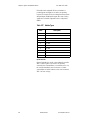
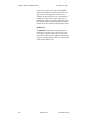
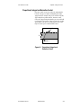
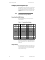
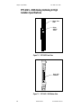
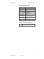
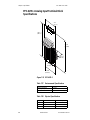
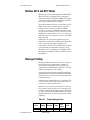
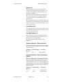
Tuning Gain
This parameter indicates the amount of delay in seconds in the load. This
characteristic of the load or plant has a significant impact on adaptive
control. A larger number indicates a longer delay between, for example
an increase in heater power and an increase in the temperature.
Values: Aggressive (0), Nominal (1), Damped 1 (2), Damped 2 (3),
Damped 3 (4) and Damped 4 (5)
Default: Nominal (1)
Modbus Address (Channels 1 to 32): 46551 to 46682
Parameter Number: 29
LogicPro Driver: Database
LogicPro Address (Channels 1 to 32): 29.1 to 29.32
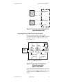
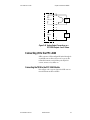
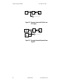
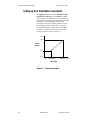
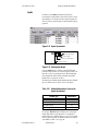
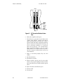
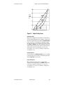
Figure 1. The Effect of Tuning Gain on Recovery from a
Load Change
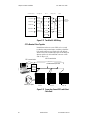
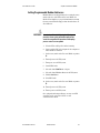
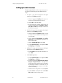
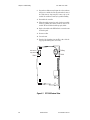
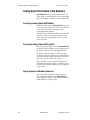
Using Adaptive Control
To set up adaptive control on one or more channels:
1. Open the
Spreadsheet Overview screen in ANAWIN3.
2. On the
Inputs spreadsheet for each analog input you have wired:
a. Choose the appropriate
Input Type for the sensor.
b. Choose
Units.
c. For any linear voltage, current, or pulse sensors, set the linear
scaling parameters (
Input Signal Lo, Input Signal Hi, PV Lo,
and
PV Hi). See Setting up User Selectable Linear Inputs on
page 98 of the PPC-2000 User's Guide.
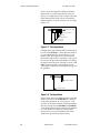
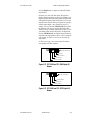
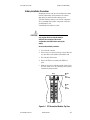
3. On the
Channels spreadsheet for each channel:

Adaptive Addendum PPC-2000 User's Guide
0600-0049-0001 rev C Watlow Anafaze 4
a. In the PV Source field, choose the input that you want to
monitor or use as feedback for closed-loop control.
b. In the
Heat Output Dest and/or Cool Output Dest fields,
choose the outputs that you want to use for closed-loop control.
c. Choose a
Heat/Cool Output Type for each output.
d. Set the
Heat/Cool Cycle Time for any outputs with Heat/ Cool
Output Type
set to Time Prop.
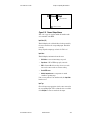
4. On the
Digital I/O spreadsheet:
a. Set the
Direction for each I/O point to be used for control to
Output.
5. On the
Channels spreadsheet:
a. For channels other than the adaptive ones, if both heat and cool
outputs are used, set the
Spread.
b. For each channel that will perform adaptive control, for the
Control Type, choose Adaptive.
c. Set the
Set Point to the desired value at least 40 engineering
units (typically degrees) above the process variable.
d. Set the
Control Mode to Auto to begin adaptive closed-loop
control.
NOTE: Only channels 1 to 8 can be selected for adaptive control.

©2004 Watlow Page 1 of 1
PPC-2000 User's Guide
Addendum
Overview
This document contains additional specifications for the PPC-2000 system.
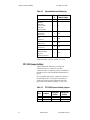
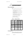
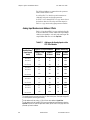
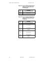
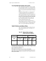
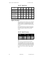
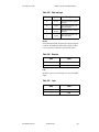
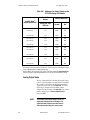
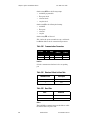
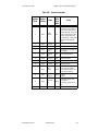
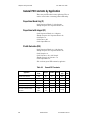
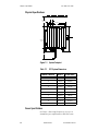
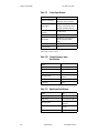
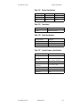
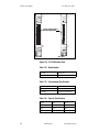
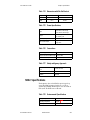
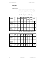
Environmental Specifications
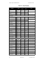
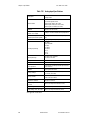
Table 1 here contains specifications in addition to those found in tables 7.4, 7.15, 7.23,
7.31, 7.39, 7.46, 7.52, 7.57, 7.62, 7.67 in the PPC-2000 User's Guide.
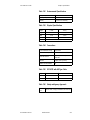
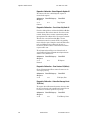
TABLE 1. Environmental Specifications
Altitude 2000 meters max
Non-Condensing Humidity 10 to 95%
Relative Humidity 80% max (ambient temperature <= 31° C)
50% max (ambient temperature = 40° C)
Pollution Category Degree 2 (per IEC 664)
Operating Temperature Range 0 to 60° C (32 to140° F)
Storage Temperature Range -20 to 70° C (-4 to 158° F)
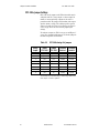
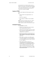
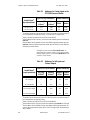
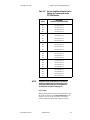
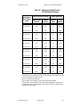
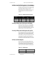
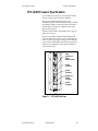
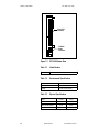
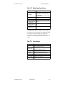
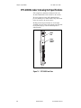
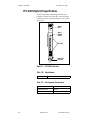
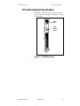
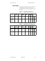
PPC IPS International Power Supply Specifications
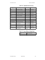
Table 2 here contains specifications in addition to those found in table 7.75 in the PPC-
2000 User's Guide.
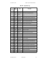
TABLE 2. Power Specifications
Input (Mains Supply) 88 to 132 Vac (120 Vac nominal)
176 to 264 Vac (240 Vac nominal)
Voltage Fluctuation < +10% of nominal voltage
Transient Over-Voltage Category II per IEC 664
Output V1: +5 Vdc @ 6 A
V2: +24 Vdc @ 4 A
Input Frequency 47 to 440 Hz
Peak Current Output 9A @ 5Vdc
6A @ 24 Vdc
1241 Bundy Blvd.
Winona, MN 55987
Phone: (507) 494-5656
Fax: (507) 452-4507

Copyright
©
1998-2002
Watlow Anafaze
Information in this manual is subject to change without notice. No part of this publication may be
reproduced, stored in a retrieval system, or transmitted in any form without written permission
from Watlow Anafaze.
Warranty
Watlow Anafaze, Incorporated warrants that the products furnished under this Agreement will be
free from defects in material and workmanship for a period of three years from the date of ship-
ment. The Customer shall provide notice of any defect to Watlow Anafaze, Incorporated within one
week after the Customer's discovery of such defect. The sole obligation and liability of Watlow
Anafaze, Incorporated under this warranty shall be to repair or replace, at its option and without
cost to the Customer, the defective product or part.
Upon request by Watlow Anafaze, Incorporated, the product or part claimed to be defective shall
immediately be returned at the Customer's expense to Watlow Anafaze, Incorporated. Replaced or
repaired products or parts will be shipped to the Customer at the expense of Watlow Anafaze,
Incorporated.
There shall be no warranty or liability for any products or parts that have been subject to misuse,
accident, negligence, failure of electric power or modification by the Customer without the written
approval of Watlow Anafaze, Incorporated. Final determination of warranty eligibility shall be
made by Watlow Anafaze, Incorporated. If a warranty claim is considered invalid for any reason,
the Customer will be charged for services performed and expenses incurred by Watlow Anafaze,
Incorporated in handling and shipping the returned unit.
If replacement parts are supplied or repairs made during the original warranty period, the warranty
period for the replacement or repaired part shall terminate with the termination of the warranty
period of the original product or part.
The foregoing warranty constitutes the sole liability of Watlow Anafaze, Incorporated and the Cus-
tomer's sole remedy with respect to the products. It is in lieu of all other warranties, liabilities, and
remedies. Except as thus provided, Watlow Anafaze, Inc. disclaims all warranties, express or
implied, including any warranty of merchantability or fitness for a particular purpose.
Please Note
: External safety devices must be used with this equipment.

Doc.# 30002-00 Rev 2.3 Watlow Anafaze iii
Table of Contents
Table of Contents iii
List of Figures ix
List of Tables xv
Overview 1
Manual Contents 1
Getting Started 2
Safety symbols 2
Contacting Watlow Anafaze 2
Initial Inspection 2
Product Features 3
System Components 3
PPC-2000 Modules 6
PPC-2000 Terminal Boards 8
Additional Components 9
Safety 9
External Safety Devices 10
External Switch Disconnect 11
Battery Safety 11
Product Markings and Symbols 11
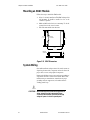
Hardware Installation 13
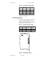
Power Supply Requirements 13
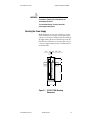
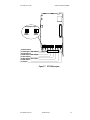
Mounting the Power Supply 15
Hardware Configuration 17
Module Addresses 17
PPC-2010 Jumper Settings 18
PPC-2030 Dip Switch Settings 19
PPC-2030 Jumper Settings 20
PPC-2040 Jumper Settings 21
PPC-205x Jumper Settings 22
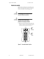
Module Disassembly 26
Mounting Modules 26
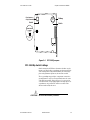
DIN Rail Mounting 27

Table of Contents PPC-2000 User’s Guide
iv Watlow Anafaze Doc.# 30002-00 Rev 2.3
Mounting Terminal Boards 28
DIN Rail Mounting 31
DIN Rail Removal 32
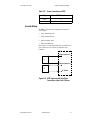
Panel Mounting 33
System Wiring 34
Wiring Recommendations 35
Noise Suppression 35
Avoiding Ground Loops 37
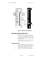
Connecting I/O to the PPC-2010 37
Connecting the TB50 to the PPC-2010 Module 37
TB50 Connections 38
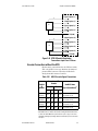
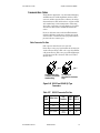
Connecting Digital Inputs 40
Connecting Counter or Frequency Inputs 41
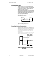
Connecting Digital Outputs 41
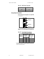
SDAC Connections 43
Connecting Analog Inputs to the PPC-2021 — 2025 45
Connecting the AITB to the PPC-202x 45
Sensor Keys 46
AITB Connections 47
Connecting Thermocouples 49
Connecting RTDs 50
Connecting Sensors with Linear Voltage Signals 52
Connecting Sensors with Linear Current Signals 53
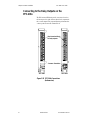
Connecting the Encoder Input Cable to the PPC-2030 55
Encoder Wiring 57
Encoder Connections without the EITB 59
Analog Output Connections 60
Connecting I/O to the PPC-2040 61
Connecting the TB50 to the PPC-2040 Module 61
TB50 Connections 62
Connecting Digital Inputs 64
Connecting Counter or Frequency Inputs 64
Connecting Digital Outputs 65
Connecting to the Relay Outputs on the PPC-206x 70
Wiring PPC-2062 Relay Outputs 71
Using Snubbers for Relay Outputs 73
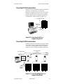
Connecting Power 77
PPC-IPS-2 Power Supply 77
Processor Module 77
Connecting Communication Ports 78
Communication Ports 78
Connecting RS-485 Communications 81

PPC-2000 User’s Guide Table of Contents
Doc.# 30002-00 Rev 2.3 Watlow Anafaze v
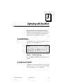
Operating with AnaWin3 89
Type Definitions 89
Closed-Loop Control 89
Feedback 90
Control Algorithm 90
Control Output Signal Forms 90
Heat and Cool Outputs 90
Prerequisites 93
Background 93
Using
AnaWin3
to Tune 94
Alarms 95
Failed Sensor Alarms 95
Global Alarm 95
Process Alarms 95
Alarm Delay 96
Setting up Process and Deviation Alarms 97
Setting Input Signal Lo and Input Signal Hi 99
Setting Engineering Units 99
Setting PV Lo and PV Hi 99
Setting Decimal Places 100
Linear 4-20mA Input Example 101
Process Variable Retransmit 102
Setting up Process Variable Retransmit 103
Process Variable Retransmit Example 104
Cascade Control 105
Setting up Cascade Control 106
Cascade Control Example 106
Ratio Control 109
Setting up Ratio Control 110
Differential Control 112
Remote Set Point 112
Logic Programs 112
Setting up Outputs for Use with a Logic Program 113
Using Logic to Set an Analog Input 113
Starting and Stopping Logic Programs 113
Controller Parameters 115
Channels 115
Digital I/O 132
Soft Integer 136
Soft Boolean 137

Table of Contents PPC-2000 User’s Guide
vi Watlow Anafaze Doc.# 30002-00 Rev 2.3
Troubleshooting 141
General Description 141
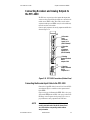
PPC-2010 Processor 141
Processor Module LEDs 147
PPC-2040 Digital I/O 151
PPC-207x Digital In 153
Troubleshooting and Corrective Actions 154
Digital Inputs and Outputs 154
Process Variable 154
Communications 155
Resetting Closed-Loop Control Parameters 156
Disabling Control 157
LogicPro and Modbus Reference 159
Overview 159
Text Conventions in the Database Sections 159
The PPC-2000 Database 160
Data Table Organization 161
How LogicPro Accesses the Database 162
Analog and Counter Input Parameters in the Database 163
Accessing Analog and Counter Input Parameters with Modbus 163
Accessing Analog and Counter Input Parameters with
LogicPro 163
Analog Input Numbers and Address Offsets 164
Analog and Encoder Input Parameters 168
Channel Parameters in the Database 172
Accessing Channel Parameters with Modbus 172
Accessing Channel Parameters with
LogicPro 173
Channel Parameters for Heat and Cool Outputs 173
Channel Parameters 173
State and Logic 195
Accessing Digital I/O Parameters with Modbus 195
Digital I/O Numbers and Address Offsets 196
Digital I/O Parameters 200
Accessing Analog Outputs with Modbus 202
Accessing Analog Outputs with
LogicPro 202
Analog Outputs and Modbus Addresses 202
Analog Output Value 204
Soft Bool and Soft Int Registers in the Database 205
Accessing Soft Bool and Soft Int Registers with Modbus 205
Accessing Soft Bool and Soft Int Registers with
LogicPro 205
Soft Bool and Soft Int Registers 205
Global Parameters in the Database 206
Accessing Global Parameters with Modbus 206
Communications Parameters 207
Global Database Parameters 209

PPC-2000 User’s Guide Table of Contents
Doc.# 30002-00 Rev 2.3 Watlow Anafaze vii
Tuning and Control 219
Introduction 219
Control Algorithms 220
On/Off Control 220
Output Control Forms 224
Output Filter 225
Proportional Band (PB) Settings 226
Integral Settings 226
Derivative Settings 227
General PID Constants by Application 228
Proportional Band Only (P) 228
Proportional with Integral (PI) 228
PI with Derivative (PID) 228
Specifications 229
System Specifications 229
Safety and Agency Approvals 229
Physical Specifications 230
Power Specifications 230
PPC-2010 Processor Specifications 231
PPC-205x Analog Out Specifications 247
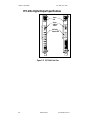
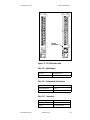
PPC-206x Digital Output Specifications 250
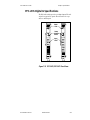
PPC-207x Digital In Specifications 253
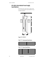
PPC-EITB-1 Encoder Input Terminal Block Specifications 258
PPC-TB50-SCSI, 50-Pin Specifications 261
SDAC Specifications 265
Inputs 266
Analog Outputs 267
Appendix A: Modbus Protocol 269
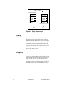
Query 270
Response 270
Message Framing 271
Address Field 272
Function Field 272
Data Field 273
Error Checking Field 273
Field Format 273
Parity Checking 274
CRC Checking 275
Read Examples 280
Appendix B: Declaration of Conformity 283
Glossary 285

Table of Contents PPC-2000 User’s Guide
viii Watlow Anafaze Doc.# 30002-00 Rev 2.3

Doc.# 30002-00 Rev 2.3 Watlow Anafaze ix
List of Figures
Overview 1
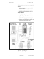
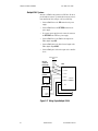
Figure 1.1—System Diagram 4
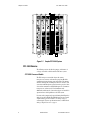
Figure 1.2—Sample PPC-2000 System 6
Hardware Installation 13
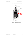
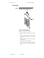
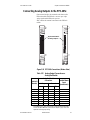
Figure 2.1—PPC-IPS-2 DIN Mounting Dimensions 15
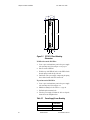
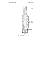
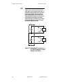
Figure 2.2—PPC-IPS-2 Panel Mounting Dimensions 16
Figure 2.3—Sample Addresses 17
Figure 2.4—PPC-2010 Jumpers 19
Figure 2.5—PPC-2030 Jumpers and Switches 20
Figure 2.6—PPC-2040 Jumper Settings 21
Figure 2.7—PPC-205x Jumpers 23
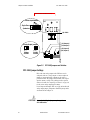
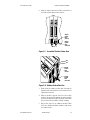
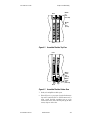
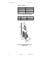
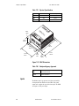
Figure 2.8—Assembled Modules Top View 24
Figure 2.9—Assembled Modules Bottom View 25
Figure 2.10—Modules Bottom/Side View 25
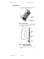
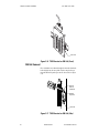
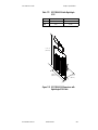
Figure 2.11—DIN Rail Latches 27
Figure 2.12—Mounting Assembled PPC Modules on a DIN rail (side) 27
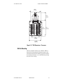
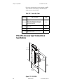
Figure 2.13—AITB Dimensions / Clearances 29
Figure 2.14—EITB Dimensions / Clearances 30
Figure 2.15—TB50 Dimensions / Clearances 31
Figure 2.16—TB50 Mounted on DIN Rail (Front) 32
Figure 2.17—TB50 Mounted on DIN Rail (Side) 32
Figure 2.18—TB50 Panel Mounted 33
Figure 2.19—SDAC Dimensions 34
Figure 2.20—PPC-2010 Connection to TB50 38
Figure 2.21—Wiring Digital Inputs 41
Figure 2.22—Encoder with 5Vdc TTL Signal 41
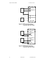
Figure 2.23—Powering Output with 5Vdc from PPC Supply 42
Figure 2.24—Powering Output with 12-24Vdc from PPC supply 42
Figure 2.25—Powering Output with Separate Power Supplies 42
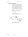
Figure 2.26—Recommended circuitry for CPUWatchdog 43
Figure 2.27—Wiring Single/Multiple SDACs 44
Figure 2.28—PPC-2021 — 2025 Connection to AITB 45
Figure 2.29—Inserting Sensor Keys in AITB 46
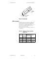
Figure 2.30—An Input Key 47
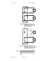
Figure 2.31—Thermocouples Connected to Differential Inputs 1 and 2 49
Figure 2.32—Thermocouples Connected to Single-ended Inputs 1 and 2 50
Figure 2.33—Wiring 2-Wire RTDs: Input 1 and 2 Shown 51
Figure 2.34—Wiring 3-Wire RTDs: Input 1 and 2 Shown 51

List of Figures PPC User’s Guide
x Watlow Anafaze Doc.# 30002-00 Rev 2.3
Figure 2.35—Connecting Linear Voltage Signals to Differential Inputs 1 and 2 52
Figure 2.36—Connecting Linear Voltage Signals to Single-ended Inputs 1 and 2 53
Figure 2.37—Connecting Current Inputs to a Differential Input Module:
Input 1, 2, and 3 Shown 53
Figure 2.38—Connecting Current Inputs to a Single-ended Analog Input
Module: Input 1 and 2 Shown 54
Figure 2.39—PPC-2030 Connections (Bottom View) 55
Figure 2.40—PPC-EITB-1 56
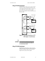
Figure 2.41—EITB Single-ended Single Phase Connections: Input 1 and 2 Shown 57
Figure 2.42—EITB Single-ended Quadrature Connections: Input 1 and 2 Shown 58
Figure 2.43—EITB Differential Single Phase Connections: Input 1 and 2 Shown 58
Figure 2.44—EITB Differential Quadrature Connections: Input 1 and 2 Shown 59
Figure 2.45—PPC-2030 Analog Out Terminal Block 60
Figure 2.46—Analog Output Connections on a PPC-2030: Outputs 1 and 2 Shown 61
Figure 2.47—PPC-2040 Connection to TB50 62
Figure 2.48—Wiring Digital Inputs 64
Figure 2.49—Single Phase Connections: Input 1 and 2 Shown 64
Figure 2.50—Quadrature Connections: Inputs 1 and 2 Shown. 65
Figure 2.51—Powering Output with 5Vdc from PPC Supply 65
Figure 2.52—Powering Output with 12-24Vdc from PPC supply 66
Figure 2.53—Powering Output with Separate Power Supplies 66
Figure 2.54—PPC-205x Connections (Bottom View) 67
Figure 2.55—Analog Output Connections on a PPC-2050 Configured for Current:
Outputs 1 and 2 Shown 68
Figure 2.56—Analog Output Connections on a PPC-2050 Configured for Voltage:
Outputs 1 and 2 shown 69
Figure 2.57—Analog Output Connections on a PPC-2051 Configured for Current and
Voltage: Outputs 1 and 2 shown 69
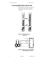
Figure 2.58—PPC-206x Connections (bottom view) 70
Figure 2.59—Relay Output Connections on a PPC-2061:
Outputs 1, 2, 9 and 10 shown 71
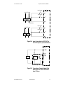
Figure 2.60—Relay Output Connections on a PPC-2062: Outputs 1 and 2 Shown 72
Figure 2.61—Snubber Connections 73
Figure 2.62—PPC-207x Connections (bottom view) 74
Figure 2.63—Input Connections to a PPC-2070 or PPC-2072:
Inputs 1 and 2 shown 74
Figure 2.64—Input Connections to a PPC-2071 or PPC-2073:
Inputs 1,2, 9 and 10 Shown 75
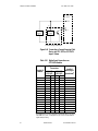
Figure 2.65—Connecting a Current Sinking Field Device to a PPC-2072 or PPC-2073:
Input 1 Shown 75
Figure 2.66—Connecting a Current Sourcing Field Device to a PPC-2072 or
PPC-2073: Input 1 Shown 76
Figure 2.67—PPC-IPS-2 Power Connections 78
Figure 2.68—RS-232 and RS-485 RJ-Type Connectors 79
Figure 2.69—Connecting One PPC to a Computer Using RS-232 81
Figure 2.70—Connecting Multiple PPCs to a Computer Using RS-485 81
Figure 2.71—RS-485 Wiring 82
Figure 2.72—Two Wire RS-485 Wiring 84
Figure 2.73—Connecting Several PPCs with Short Cable Runs 84

PPC User’s Guide List of Figures
Doc.# 30002-00 Rev 2.3 Watlow Anafaze xi
Operating with AnaWin3 89
Figure 3.1—Sample Screen Text 89
Figure 3.2—Process Variable Alarms 96
Figure 3.3—Linear Input Example 98
Figure 3.4—Linear Scaling of the Analog Input for Retransmit on the Heat or Cool
Output 102
Figure 3.5—Sample Application Using Process Variable Retransmit 104
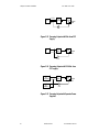
Figure 3.6—How the Secondary Channel’s Set Point is Determined When the
Primary Channel Has Heat and Cool Outputs 105
Figure 3.7—How the Secondary Channel’s Set Point is Determined When the Primary
Channel Has Only a Heat Output 106
Figure 3.8—Sample Application Using Cascade Control 107
Figure 3.9—The Secondary Channel’s Set Point is Determined by the Primary
Channel’s Process Variable 109
Figure 3.10—Relationship between the Master Channel’s Process Variable and the
Ratio Channel’s Set Point. 110
Figure 3.11—Sample Application Using Ratio Control 111
Figure 3.12—Channels Spreadsheet 115
Figure 3.13—Output Scaling (Heat/Cool) Curves 121
Figure 3.14—Alarms Spreadsheet 123
Figure 3.15—Inputs Spreadsheet 127
Figure 3.16—Analog Input Names 127
Figure 3.17—Pulse Input Names 128
Figure 3.18—Soft Input Names 128
Figure 3.19—Channel Output Names 129
Figure 3.20—Dig I/O Spreadsheet 132
Figure 3.21—PPC-2010 and PPC-204X Digital I/O Names 133
Figure 3.22—PPC-206X and PPC-207X Digital I/O Names 133
Figure 3.23—Outputs Spreadsheet 135
Figure 3.24—Analog Output Names 135
Figure 3.25—Soft Int Spreadsheet 136
Figure 3.26—Soft BOOL Spreadsheet 137
Figure 3.27—PPC Globals Screen 138
Troubleshooting 141
Figure 4.1—Assembled Modules Top View 143
Figure 4.2—Assembled Modules Bottom View 143
Figure 4.3—PPC-2010 Internal View 144
Figure 4.4—PPC Assembled Modules Top View 145
Figure 4.5—PPC Assembled Modules Bottom View 146

List of Figures PPC User’s Guide
xii Watlow Anafaze Doc.# 30002-00 Rev 2.3
LogicPro and Modbus Reference 159
Figure 5.1—Sample Text 160
Figure 5.2—Output Scaling Curves 185
Tuning and Control 219
Figure 6.1—On/Off Control 220
Figure 6.2—Proportional Control 221
Figure 6.3—Proportional and Integral Control 222
Figure 6.4—Proportional, Integral and Derivative Control 223
Figure 6.5—Example Time Proportioning and Distributed Zero Crossing
Waveforms 224
Specifications 229
Figure 7.1—System Footprint 230
Figure 7.2—PPC-2010 Front View 231
Figure 7.3—PPC-2010 Bottom View 232
Figure 7.4—PPC-2021 Front View 236
Figure 7.5—PPC-2021 - 2025 Bottom View 236
Figure 7.6—PPC-2030 Front View 240
Figure 7.7—PPC-2030 Bottom View 241
Figure 7.8—PPC-2040 Front View 244
Figure 7.9—PPC-2050 Front View 247
Figure 7.10—PPC-2050 Bottom View 248
Figure 7.11—PPC-206x Front View 250
Figure 7.12—PPC-206x Bottom View 251
Figure 7.13—PPC-2070, PPC-2071 Front Views 253
Figure 7.14—PPC-207x Bottom Views 254
Figure 7.15—PPC-AITB-1 256
Figure 7.16—PPC-AITB Dimensions with Straight SCSI Cable 257
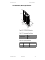
Figure 7.17—PPC-EITB-1 258
Figure 7.18—PPC-EITB Dimensions with HD-Type Cable 260
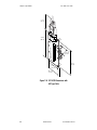
Figure 7.19—PPC-TB50-SCSI Dimensions 261
Figure 7.20—PPC-TB50-SCSI Dimensions with Straight SCSI Cable 262
Figure 7.21—PPC-TB50-SCSI Dimensions with Right-Angle SCSI Cable 263
Figure 7.22—PPC-IPS-2 264
Figure 7.23—SDAC Dimensions 266
Appendix A: Modbus Protocol 269
Figure A.1—Query—Response Cycle 270

Doc.# 30002-00 Rev 2.3 Watlow Anafaze xiii
List of Tables
Overview 1
Table 1.1—PPC-2000 System Modules 5
Table 1.2—PPC-2000 Terminal Boards and Peripheral Modules 5
Table 1.3— Analog Terminal Board Keys 5
Hardware Installation 13
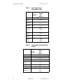
Table 2.2—Power Supply Current Requirements at 24Vdc 14
Table 2.3—Power Supply Screw Mounting 16
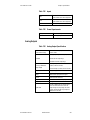
Table 2.4—System Modules and Addressing 18
Table 2.5—PPC-2010 Processor Module Jumpers 18
Table 2.6—PPC-2030 Analog Output Jumpers 21
Table 2.7—PPC-2040 Counter Input Jumpers 21
Table 2.8—PPC-205x Analog Out Jumpers 22
Table 2.9—Cable Recommendations 35
Table 2.10—Processor Module I/O Connections 39
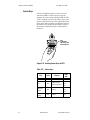
Table 2.11—Sensor Keys 46
Table 2.12—Numbers and Types of Inputs by Module Type 47
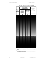
Table 2.13—Sensor Connections to the AITB 48
Table 2.14—Power Connections on AITB 49
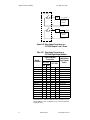
Table 2.15—Encoder Connections to the EITB Connected to J3 on the PPC-2030 56
Table 2.16—Encoder Connections to the EITB Connected to J4 on the PPC-2030 56
Table 2.17—Power Connections on EITB 57
Table 2.18—HD-15 Encoder Signal Connections 59
Table 2.19—HD-15 Power Connections 60
Table 2.20—Analog Output Connections on Encoder In Analog Out Module 60
Table 2.21—Digital I/O Module Connections 63
Table 2.22—Analog Output Connections on Analog Out Module 67
Table 2.23—Relay Output Connections on PPC-206x Digital Output Modules 72
Table 2.24—Digital Input Connections on PPC-207x Modules 76
Table 2.25—PPC-IPS-2 Voltage Input Switch Settings 77
Table 2.26—Power Supply Connections 77
Table 2.27—RS-232 Connector Pin Outs 79
Table 2.28—RS-485 Connector Pin Out and Connections 80
Table 2.29—RTS/CTS Pins in DB-9 and DB-25 Connectors 80
Table 2.30—485 Terminal Block Pin Assignment 83
Table 2.31—PPC-2010 Rotary Switch Configuration 86

List of Tables PPC User’s Guide
xiv Watlow Anafaze Doc.# 30002-00 Rev 2.3
Operating with AnaWin3 89
Table 3.1—Control Types PID1 and PID2 91
Table 3.2—Alarm Types 95
Table 3.3—Range and Sensitivity of theCustom Linear Input Types 99
Table 3.4—PV Range permitted for various Decimal Places Settings 100
Table 3.5—Scaling Parameters for 0-10Vdc Linear Input Example 101
Table 3.6—Scaling Parameters for 4-20mA Linear Input Example 101
Table 3.7—Scaling Parameters for 0-1Vdc Linear Input Example 102
Table 3.8—Retransmit Channel Parameter Settings 104
Table 3.9—Primary Channel Parameter Settings 107
Table 3.10—Secondary Channel Parameter Settings 108
Table 3.11—Ratio Channel Parameter Settings 111
Table 3.12—AnaWin3 Control Types 118
Table 3.14—Module Abbreviations Seen on the Inputs Spreadsheet 127
Table 3.16—Units 131
Table 3.18—Function Values 134
Table 3.19—Module Abbreviations Seen on the Outputs Spreadsheet 135
Table 3.20—System Status 139
Table 3.21—Global Settings 139
LogicPro and Modbus Reference 159
Table 5.1—Parameter Names & Abbreviations 159
Table 5.2—Example Database Table 160
Table 5.3—Addresses for Analog Inputs on the PPC-202x Modules 164
Table 5.4—Addresses for Encoder Inputs on the PPC-2030 Encoder In Analog Out
Module 165
Table 5.5—Addresses for Counter Inputs on the PPC-2010 Processor Module 166
Table 5.6—Addresses for Soft Inputs and Channel Outputs 166
Table 5.7—Addresses for Encoder Inputs on the PPC-2040 Digital I/O Modules 167
Table 5.8—Input Parameters 168
Table 5.9—Input Status 169
Table 5.11—Temperature Scale Conversion 171
Table 5.13—Process Variable and Setpoint Source Settings for Analog Inputs on the
PPC-202x Modules 176
Table 5.16—Process Variable and Setpoint Source Settings for Soft Input and
Channel Out Registers 178
Table 5.18—Control Mode 180
Table 5.19—Control Types 181
Table 5.21—Heat/Cool Curve 184
Table 5.22—Output Destinations for Digital Outputs on the PPC-2010 Module 186
Table 5.26—Output Destinations for Analog Outputs on the PPC-205x Modules 189
Table 5.27—Output Destinations for Soft Boolean and Soft Integers 190
Table 5.28—Alarm Status 190
Table 5.30—Alarm and Control Functionality 192
Table 5.31—Alarm Acknowledge 192
Table 5.32—Alarm Enable/Disable 192
Table 5.33—Database Offsets and Sample Modbus Addresses for Digital I/O 196
Table 5.37—Digital I/O Uses 200
Page is loading ...
Page is loading ...
Page is loading ...
Page is loading ...
Page is loading ...
Page is loading ...
Page is loading ...
Page is loading ...
Page is loading ...
Page is loading ...
Page is loading ...
Page is loading ...
Page is loading ...
Page is loading ...
Page is loading ...
Page is loading ...
Page is loading ...
Page is loading ...
Page is loading ...
Page is loading ...
Page is loading ...
Page is loading ...
Page is loading ...
Page is loading ...
Page is loading ...
Page is loading ...
Page is loading ...
Page is loading ...
Page is loading ...
Page is loading ...
Page is loading ...
Page is loading ...
Page is loading ...
Page is loading ...
Page is loading ...
Page is loading ...
Page is loading ...
Page is loading ...
Page is loading ...
Page is loading ...
Page is loading ...
Page is loading ...
Page is loading ...
Page is loading ...
Page is loading ...
Page is loading ...
Page is loading ...
Page is loading ...
Page is loading ...
Page is loading ...
Page is loading ...
Page is loading ...
Page is loading ...
Page is loading ...
Page is loading ...
Page is loading ...
Page is loading ...
Page is loading ...
Page is loading ...
Page is loading ...
Page is loading ...
Page is loading ...
Page is loading ...
Page is loading ...
Page is loading ...
Page is loading ...
Page is loading ...
Page is loading ...
Page is loading ...
Page is loading ...
Page is loading ...
Page is loading ...
Page is loading ...
Page is loading ...
Page is loading ...
Page is loading ...
Page is loading ...
Page is loading ...
Page is loading ...
Page is loading ...
Page is loading ...
Page is loading ...
Page is loading ...
Page is loading ...
Page is loading ...
Page is loading ...
Page is loading ...
Page is loading ...
Page is loading ...
Page is loading ...
Page is loading ...
Page is loading ...
Page is loading ...
Page is loading ...
Page is loading ...
Page is loading ...
Page is loading ...
Page is loading ...
Page is loading ...
Page is loading ...
Page is loading ...
Page is loading ...
Page is loading ...
Page is loading ...
Page is loading ...
Page is loading ...
Page is loading ...
Page is loading ...
Page is loading ...
Page is loading ...
Page is loading ...
Page is loading ...
Page is loading ...
Page is loading ...
Page is loading ...
Page is loading ...
Page is loading ...
Page is loading ...
Page is loading ...
Page is loading ...
Page is loading ...
Page is loading ...
Page is loading ...
Page is loading ...
Page is loading ...
Page is loading ...
Page is loading ...
Page is loading ...
Page is loading ...
Page is loading ...
Page is loading ...
Page is loading ...
Page is loading ...
Page is loading ...
Page is loading ...
Page is loading ...
Page is loading ...
Page is loading ...
Page is loading ...
Page is loading ...
Page is loading ...
Page is loading ...
Page is loading ...
Page is loading ...
Page is loading ...
Page is loading ...
Page is loading ...
Page is loading ...
Page is loading ...
Page is loading ...
Page is loading ...
Page is loading ...
Page is loading ...
Page is loading ...
Page is loading ...
Page is loading ...
Page is loading ...
Page is loading ...
Page is loading ...
Page is loading ...
Page is loading ...
Page is loading ...
Page is loading ...
Page is loading ...
Page is loading ...
Page is loading ...
Page is loading ...
Page is loading ...
Page is loading ...
Page is loading ...
Page is loading ...
Page is loading ...
Page is loading ...
Page is loading ...
Page is loading ...
Page is loading ...
Page is loading ...
Page is loading ...
Page is loading ...
Page is loading ...
Page is loading ...
Page is loading ...
Page is loading ...
Page is loading ...
Page is loading ...
Page is loading ...
Page is loading ...
Page is loading ...
Page is loading ...
Page is loading ...
Page is loading ...
Page is loading ...
Page is loading ...
Page is loading ...
Page is loading ...
Page is loading ...
Page is loading ...
Page is loading ...
Page is loading ...
Page is loading ...
Page is loading ...
Page is loading ...
Page is loading ...
Page is loading ...
Page is loading ...
Page is loading ...
Page is loading ...
Page is loading ...
Page is loading ...
Page is loading ...
Page is loading ...
Page is loading ...
Page is loading ...
Page is loading ...
Page is loading ...
Page is loading ...
Page is loading ...
Page is loading ...
Page is loading ...
Page is loading ...
Page is loading ...
Page is loading ...
Page is loading ...
Page is loading ...
Page is loading ...
Page is loading ...
Page is loading ...
Page is loading ...
Page is loading ...
Page is loading ...
Page is loading ...
Page is loading ...
Page is loading ...
Page is loading ...
Page is loading ...
Page is loading ...
Page is loading ...
Page is loading ...
Page is loading ...
Page is loading ...
Page is loading ...
Page is loading ...
Page is loading ...
Page is loading ...
Page is loading ...
Page is loading ...
Page is loading ...
Page is loading ...
Page is loading ...
Page is loading ...
Page is loading ...
Page is loading ...
Page is loading ...
Page is loading ...
Page is loading ...
Page is loading ...
Page is loading ...
Page is loading ...
Page is loading ...
Page is loading ...
Page is loading ...
Page is loading ...
Page is loading ...
Page is loading ...
Page is loading ...
Page is loading ...
Page is loading ...
Page is loading ...
Page is loading ...
Page is loading ...
Page is loading ...
Page is loading ...
Page is loading ...
Page is loading ...
Page is loading ...
Page is loading ...
Page is loading ...
Page is loading ...
Page is loading ...
Page is loading ...
Page is loading ...
Page is loading ...
Page is loading ...
Page is loading ...
Page is loading ...
Page is loading ...
Page is loading ...
Page is loading ...
Page is loading ...
Page is loading ...
Page is loading ...
Page is loading ...
Page is loading ...
Page is loading ...
Page is loading ...
Page is loading ...
Page is loading ...
Page is loading ...
Page is loading ...
Page is loading ...
-
 1
1
-
 2
2
-
 3
3
-
 4
4
-
 5
5
-
 6
6
-
 7
7
-
 8
8
-
 9
9
-
 10
10
-
 11
11
-
 12
12
-
 13
13
-
 14
14
-
 15
15
-
 16
16
-
 17
17
-
 18
18
-
 19
19
-
 20
20
-
 21
21
-
 22
22
-
 23
23
-
 24
24
-
 25
25
-
 26
26
-
 27
27
-
 28
28
-
 29
29
-
 30
30
-
 31
31
-
 32
32
-
 33
33
-
 34
34
-
 35
35
-
 36
36
-
 37
37
-
 38
38
-
 39
39
-
 40
40
-
 41
41
-
 42
42
-
 43
43
-
 44
44
-
 45
45
-
 46
46
-
 47
47
-
 48
48
-
 49
49
-
 50
50
-
 51
51
-
 52
52
-
 53
53
-
 54
54
-
 55
55
-
 56
56
-
 57
57
-
 58
58
-
 59
59
-
 60
60
-
 61
61
-
 62
62
-
 63
63
-
 64
64
-
 65
65
-
 66
66
-
 67
67
-
 68
68
-
 69
69
-
 70
70
-
 71
71
-
 72
72
-
 73
73
-
 74
74
-
 75
75
-
 76
76
-
 77
77
-
 78
78
-
 79
79
-
 80
80
-
 81
81
-
 82
82
-
 83
83
-
 84
84
-
 85
85
-
 86
86
-
 87
87
-
 88
88
-
 89
89
-
 90
90
-
 91
91
-
 92
92
-
 93
93
-
 94
94
-
 95
95
-
 96
96
-
 97
97
-
 98
98
-
 99
99
-
 100
100
-
 101
101
-
 102
102
-
 103
103
-
 104
104
-
 105
105
-
 106
106
-
 107
107
-
 108
108
-
 109
109
-
 110
110
-
 111
111
-
 112
112
-
 113
113
-
 114
114
-
 115
115
-
 116
116
-
 117
117
-
 118
118
-
 119
119
-
 120
120
-
 121
121
-
 122
122
-
 123
123
-
 124
124
-
 125
125
-
 126
126
-
 127
127
-
 128
128
-
 129
129
-
 130
130
-
 131
131
-
 132
132
-
 133
133
-
 134
134
-
 135
135
-
 136
136
-
 137
137
-
 138
138
-
 139
139
-
 140
140
-
 141
141
-
 142
142
-
 143
143
-
 144
144
-
 145
145
-
 146
146
-
 147
147
-
 148
148
-
 149
149
-
 150
150
-
 151
151
-
 152
152
-
 153
153
-
 154
154
-
 155
155
-
 156
156
-
 157
157
-
 158
158
-
 159
159
-
 160
160
-
 161
161
-
 162
162
-
 163
163
-
 164
164
-
 165
165
-
 166
166
-
 167
167
-
 168
168
-
 169
169
-
 170
170
-
 171
171
-
 172
172
-
 173
173
-
 174
174
-
 175
175
-
 176
176
-
 177
177
-
 178
178
-
 179
179
-
 180
180
-
 181
181
-
 182
182
-
 183
183
-
 184
184
-
 185
185
-
 186
186
-
 187
187
-
 188
188
-
 189
189
-
 190
190
-
 191
191
-
 192
192
-
 193
193
-
 194
194
-
 195
195
-
 196
196
-
 197
197
-
 198
198
-
 199
199
-
 200
200
-
 201
201
-
 202
202
-
 203
203
-
 204
204
-
 205
205
-
 206
206
-
 207
207
-
 208
208
-
 209
209
-
 210
210
-
 211
211
-
 212
212
-
 213
213
-
 214
214
-
 215
215
-
 216
216
-
 217
217
-
 218
218
-
 219
219
-
 220
220
-
 221
221
-
 222
222
-
 223
223
-
 224
224
-
 225
225
-
 226
226
-
 227
227
-
 228
228
-
 229
229
-
 230
230
-
 231
231
-
 232
232
-
 233
233
-
 234
234
-
 235
235
-
 236
236
-
 237
237
-
 238
238
-
 239
239
-
 240
240
-
 241
241
-
 242
242
-
 243
243
-
 244
244
-
 245
245
-
 246
246
-
 247
247
-
 248
248
-
 249
249
-
 250
250
-
 251
251
-
 252
252
-
 253
253
-
 254
254
-
 255
255
-
 256
256
-
 257
257
-
 258
258
-
 259
259
-
 260
260
-
 261
261
-
 262
262
-
 263
263
-
 264
264
-
 265
265
-
 266
266
-
 267
267
-
 268
268
-
 269
269
-
 270
270
-
 271
271
-
 272
272
-
 273
273
-
 274
274
-
 275
275
-
 276
276
-
 277
277
-
 278
278
-
 279
279
-
 280
280
-
 281
281
-
 282
282
-
 283
283
-
 284
284
-
 285
285
-
 286
286
-
 287
287
-
 288
288
-
 289
289
-
 290
290
-
 291
291
-
 292
292
-
 293
293
-
 294
294
-
 295
295
-
 296
296
-
 297
297
-
 298
298
-
 299
299
-
 300
300
-
 301
301
-
 302
302
-
 303
303
-
 304
304
-
 305
305
-
 306
306
-
 307
307
-
 308
308
-
 309
309
-
 310
310
-
 311
311
-
 312
312
-
 313
313
-
 314
314
-
 315
315
-
 316
316
-
 317
317
-
 318
318
-
 319
319
-
 320
320


Watlow PPC-2000 User guide
- Category
- Digital & analog I/O modules
- Type
- User guide
Ask a question and I''ll find the answer in the document
Finding information in a document is now easier with AI
Related papers
-
Watlow 8PID Controller User manual
-
-
-
Watlow Electric Gateway & DeviceNet User guide
-
-
-
-
-
-
Other documents
-
-
 ThermoMart PID-8CH Owner's manual
-
Advantech PPC Series User manual
-
Vents Modbus table for connecting A21 automation to BMS User manual
-
 ThermoMart Multi Channel Controller Owner's manual
-
Frequency Central Cryptograf User guide
-
 Channel Master 900 User manual
-
Wavetronix Click 114 User guide
-
Duracell MN21 User manual
-
Chromalox 4081 Quick start guide


