Masibus Process Indicator 409 User manual
- Type
- User manual

Temperature Indicator: 409
REF NO: m59A/om/101
Issue NO: 16
Page 1 of 36
User’s Manual
409 Temperature Indicator with Alarm
Masibus Automation and Instrumentation Pvt. Ltd.
B/30, GIDC Electronics Estate,
Sector-25, Gandhinagar-382044, Gujarat, India
Phone : +91-79-23287275/79.
Fax : +91-79-23287281.
Email: [email protected]
Web: www.masibus.com

Temperature Indicator: 409
REF NO: m59A/om/101
Issue NO: 16
Page 2 of 36
Contents
1. Introduction ..................................................................................................................... 4
1.1 Product Overview/Description .............................................................................................................................. 4
1.2 Model and Suffix code ........................................................................................................................................... 4
1.3 Accessory .............................................................................................................................................................. 4
2. Safety/Warning Precaution ............................................................................................ 5
3. Front Panel Description ................................................................................................. 5
3.1 Keyboard and Operation ....................................................................................................................................... 5
4. Panel Cutout Dimension ................................................................................................ 6
5. Terminal Arrangement Diagram .................................................................................... 7
6. Configuration Guidelines ............................................................................................... 7
6.1 Menu Parameter List............................................................................................................................................. 7
6.2 Menu Layout for 409 ........................................................................................................................................... 11
6.3 Main Menu for 409 ............................................................................................................................................. 12
7. Alarm Operation ........................................................................................................... 14
7.1 Alarm type ........................................................................................................................................................... 14
7.2 Status of ALARM/TRIP ......................................................................................................................................... 14
7.3 Latching of ALARM .............................................................................................................................................. 14
7.4 HH Logic .............................................................................................................................................................. 14
7.5 HL Logic ............................................................................................................................................................... 15
7.6 LL Logic ................................................................................................................................................................ 15
7.7 Open sensor UP scale/DOWN scale .................................................................................................................... 16
7.8 HH Logic .............................................................................................................................................................. 16
7.9 HL Logic ............................................................................................................................................................... 16
7.10 LL Logic ................................................................................................................................................................ 17
7.11 Messages during OPEN SENSOR condition ......................................................................................................... 17
7.12 Retransmission output during OPEN sensor/Diode Open condition ................................................................... 18
7.13 Relay Delay.......................................................................................................................................................... 20
7.14 Control Relay ....................................................................................................................................................... 20
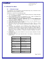
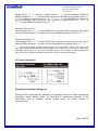
8. Calibration Procedure .................................................................................................. 24
8.1 Calibration for Input ............................................................................................................................................ 24

Temperature Indicator: 409
REF NO: m59A/om/101
Issue NO: 16
Page 3 of 36
8.2 Calibration for Retransmission ............................................................................................................................ 25
9. Communication Parameter .......................................................................................... 25
9.1 Introduction ........................................................................................................................................................ 25
9.2 Parameter Address Details.................................................................................................................................. 26
9.3 Exceptional Response .......................................................................................................................................... 28
10. Technical Specifications .............................................................................................. 29
10.1 Input Specification .............................................................................................................................................. 29
10.2 Output Specifications .......................................................................................................................................... 31
10.3 General Specifications ......................................................................................................................................... 31
10.4 Power Supply ....................................................................................................................................................... 32
10.5 Isolation .............................................................................................................................................................. 32
10.6 Communication Specifications ............................................................................................................................ 33
11. Appendix ....................................................................................................................... 34
11.1 Troubleshooting .................................................................................................................................................. 34
11.2 Jumper Location for Retransmission Output ....................................................................................................... 34
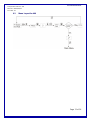
11.3 Square Root Linearization ................................................................................................................................... 35
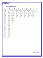
11.4 Digital Input ........................................................................................................................................................ 35
11.5 Load connection.................................................................................................................................................... 36

Temperature Indicator: 409
REF NO: m59A/om/101
Issue NO: 16
Page 4 of 36
1. Introduction
1.1 Product Overview/Description
409 is a powerful micro-controller based process indicator, designed to accept
multiple input types and two programmable set points with individual relays. Model-
409accepts 21 different types of inputs (all industry standard input) which are field
configurable facilitates plant operator to use in any application. 409 is easy to
operate and configuration is user friendly.
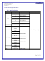
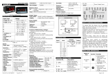
1.2 Model and Suffix code
Check the model and suffix codes to confirm that the product received is one which
was ordered.
MODEL
INPUT
Digital Input*
Power Supply
COMMUNICATIO
N
RETRANSMISSION O/P
409
1
E
N
None
U1
85-265VAC/
100-300VDC
N
NONE
N
None
2
J
Y
Yes
U2
18-36VDC
Y
RS485
C
4-20mA
3
K
D
0-20mA
4
T
E
1-5V
5
B
F
0-5V
6
R
G
0-10V
7
S
9
PT-100
C
4-20 mA
D
0-20mA
E
1-5V
F
0-5V
G
0-10V
H
0-2 V
I
0.4 – 2V
R
±75mV
U
0-75mV
V
0-400Ω
W
0-6000Ω
M
Serial RS
485
S
Special
Table 1.
1.3 Accessory
The product is provided with the following accessory. (Seethe table2below).
Table 2.
No
Item name
Part number
Qty
Remarks
1
Mounting Clamps
-
1

Temperature Indicator: 409
REF NO: m59A/om/101
Issue NO: 16
Page 5 of 36
2. Safety/Warning Precaution
The product and the instruction manual describe important information to prevent
possible harm to users and damage to the property and to use the product safely.
Understand the following description (signs and symbols), read the text and
Observe Descriptions.
DESCRIPTION OF SIGNS
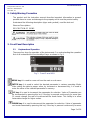
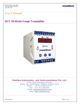
3. Front Panel Description
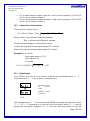
3.1 Keyboard and Operation
There are four keys for operation of the instruments. For understanding the operation
first of all understand the functionality of keys as shown in Fig.1.
Fig 1. Front Panel 409
MENU key: It is used to come out from the main or sub menu.
ENTER key: It is used to select the desired parameter in various operating Mode.
After setting the data to proper value, by increment or decrement key, it is used to
enter the value of the selected parameter in memory.
UP key: It is used to increment the parameter for selection. Value of Parameter can
be incremented by pressing this key. If the key is pressed continuously for more than
10 counts change, the rate of increment will be made faster. This facility is to allow
faster data change for higher values.
DOWN key: It is used to decrement the parameter for selection. Value of parameter
can be decremented by pressing this key. If the key is pressed continuously for more

Temperature Indicator: 409
REF NO: m59A/om/101
Issue NO: 16
Page 6 of 36
than 10 counts change, the rate of decrement will be made faster. This facility is to
allow faster data change for higher values. User presses during RUN mode for
Thermocouple input it shows ambient value.
Communication Status lamps: Lamps will blink when communication is on.
Alarm status lamps: When alarm occurs respective alarm lamp will on.
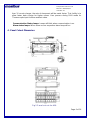
4. Panel Cutout Dimension
Fig 2.Panel cut out for 409

Temperature Indicator: 409
REF NO: m59A/om/101
Issue NO: 16
Page 7 of 36
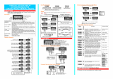
5. Terminal Arrangement Diagram
Fig 3. Terminal arrangement for 409
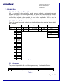
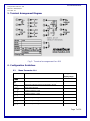
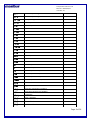
6. Configuration Guidelines
6.1 Menu Parameter List
Parameter
Name
Setting and
Display range
pass
Pass word
0001 – 9999
ok
Message indicates password entered correctly
FAIL
Message indicates password entered is wrong.
INput
Input type selection
Tc-e
Thermocouple ‘E’ type
Tc-j
Thermocouple ‘J’ type
Tc-k
Thermocouple ‘K’ type
Tc-t
Thermocouple ‘T’ type
Tc-b
Thermocouple ‘B’ type

Temperature Indicator: 409
REF NO: m59A/om/101
Issue NO: 16
Page 8 of 36
Tc-r
Thermocouple ‘R’ type
Tc-s
Thermocouple ‘S’ type
Pt 100
RTD pt100 type
0.-4k
0-400Ω potentiometer
0-6k
0-6000Ω potentiometer
1-10v
± 10 volt DC
0-10v
0-10 volt DC
0-5v
0-5 volt DC
1-5v
1-5 volt DC
0-2v
0-2 volt DC
.4-2v
0.4-2 volt DC
-10-20
-10-20 mV DC
1-75
± 75 mV DC
0-75
0-75 mV DC
Serl
Serial input
4-20
4-20 mA DC
0-20
0-20 mA DC
Dp
Decimal point
0
No decimal point.
.0
Decimal point at unit position
.00
Decimal point at 10th position
.000
Decimal point at 100th position
.0000
Decimal point at 1000th position
Zero
Zero enter
SpaN
Span enter
INLO
Input low value(Input Scalability)
INHI
Input high value(Input Scalability)
CalIb
Calibration
Cals
Span calibration
Calz
Zero calibration
Cala
Ambient calibration

Temperature Indicator: 409
REF NO: m59A/om/101
Issue NO: 16
Page 9 of 36
Alarm
Alarm Logic
Atype
Alarm type
hh
High-High logic
hl
High-Low logic
ll
Low-Low logic
selCt
Selection for Alarm 1 & 2.
Al1
Alarm 1
Al2
Alarm 2
Alarm
Alarm selection
TrIp
Trip selection
Latch
Latch status
yes
Latch Yes
No
Latch No
hyst
Hysteresis
0-255
Sensr
Sensor logic selection
Up
Up scale logic
dowN
Down scale logic
Setp1
Set point 1 for Alarm 1
Setp2
Set point 2 for Alarm 2
Rldly
Relay delay
0-9999
ctrly
Control relay logic
oN
On control relay
Off
OFF control relay
Comun
485-Communication
Sr-No
Serial number for Modbus.
1-247
Baud
Baud rate selection
4800
4800
9600
9600
19200
19200
38400
38400
Retrn
Retransmission

Temperature Indicator: 409
REF NO: m59A/om/101
Issue NO: 16
Page 10 of 36
Table 3.
*When 24V Signal applied momentarily at the DI terminal (or Power OFF) then it will clear
both values and same value will be stored in PV HI and in PV LO. Input is OPEN then
message OVER will be in PV HI and UNDER will be in PV LO. Note that during power on
wait until all functionality initialized otherwise PV HI/LO values will be wrong.
Ret v
Retransmission voltage
0-10v
Output 0-10V
0-5v
Output 0-5V
1-5v
Output 1-5V
Ret mA
Retransmission current
0-20
Output 0-20mA
4-20
Output 4-20mA
R cal
Retransmission calibration
Rtn s
Retransmission span
Rtn z
Retransmission zero
DI Ip
Digital input
filt
Digital Filter
0-60
PV hi*
Maximum Process valuewhich instrument has
measured*
PV Lo
Minimum process value which instrument has
measured*
tout
Time out
1-32
Sqrt
Square Root
yes
Square Root Yes
No
Square Root No
BrIht
Brightness
1-100
chaNg
Change of password
0001 – 9999
ok
Message indicates password change correctly
doPEN
Sensor Diode is OPEN

Temperature Indicator: 409
REF NO: m59A/om/101
Issue NO: 16
Page 11 of 36
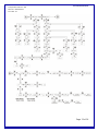
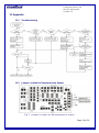
6.2 Menu Layout for 409

Temperature Indicator: 409
REF NO: m59A/om/101
Issue NO: 16
Page 12 of 36
6.3 Main Menu for 409

Temperature Indicator: 409
REF NO: m59A/om/101
Issue NO: 16
Page 13 of 36

Temperature Indicator: 409
REF NO: m59A/om/101
Issue NO: 16
Page 14 of 36
7. Alarm Operation
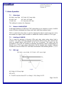
7.1 Alarm type
HH-high, very high. AL1-high, AL2-very high
HL-high, low AL1-low, AL2-high.
LL-low, low AL1-very low, AL2-low.
This setting is common for all groups.
7.2 Status of ALARM/TRIP
It will toggle between ALARM and TRIP depending up on selection in menu. ALARM
mode is further subdivided into Alarm with Latch and Alarm without Latch.
TRIP is useful when the relay is used for tripping the plant or device and it is not to
be started once again. Open condition is treated as normal condition in TRIP type.
7.3 Latching of ALARM
This is used for latching of discrete LEDs and relay status when alarm limit is
crossed. This option will keep discrete LEDs/Relay latched even after channel has
come to normal status until ENTER (ACK) key is pressed. This option can be
changed to YES or NO for enabling or disabling respectively. When configurations of
Alarms are of TRIP type, these parameters will be skipped from display. Different
conditions for the ALARM/TRIP have been mentioned in the following table 6 ,7, 8, 9.
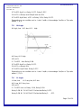
7.4 HH Logic
HH-high, very high. AL1-high, AL2-very high
Fig 4.
AL1-High, AL2-Very High
SP2>SP1
If PV>SP1 but, less then SP2 => Relay 1- ON, Relay 2-OFF.

Temperature Indicator: 409
REF NO: m59A/om/101
Issue NO: 16
Page 15 of 36
If PV<SP1-Hyst1 => Relay 1-OFF, Relay 2-OFF.
PV>SP2 => Relay1 and Relay2 both are ON.
If PV<SP2-Hyst2 but, >SP1 => Relay 1-ON, Relay 2-OFF.
Depending up on condition set i.e. Latch Yes/No, Acknowledge Yes/No or Trip refer
table6 ,7, 8, 9.
7.5 HL Logic
HL-high, low AL1-low, AL2- high.
Fig 5.
AL1-low, AL2- High
SP2>SP1
If PV>SP2 then Relay 2-ON.
If PV<SP2-Hyst2 => Relay 2-OFF.
PV<SP1 => Relay1 ON.
If PV>SP1+Hyst1 then. Relay 1-OFF.
Depending up on condition set i.e. Latch Yes/No, Acknowledge Yes/No or Trip refer
table 6 ,7, 8, 9.
7.6 LL Logic
LL-low, low AL1-very low, AL2-low.
AL1-Low, AL2-Very Low
SP2>SP1
If PV<SP1 then => Relay 1-ON, Relay 2-ON
Relay 1-ON till PV>SP1+HYS1 after that Relay 1-OFF.
Relay 2-ON till PV>SP2+HYS2 after that Relay 2- OFF.

Temperature Indicator: 409
REF NO: m59A/om/101
Issue NO: 16
Page 16 of 36
Fig 6.
Depending upon condition set i.e. Latch Yes/No, Acknowledge Yes/No or Trip refer
table 6 ,7, 8, 9.
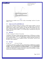
7.7 Open sensor UP scale/DOWN scale
This is used to define the state of the alarms in OPEN sensor condition. It can be
configured as UP Scale or DOWN Scale by keys.This condition works if and only if
OPEN sensor condition occurs. Suppose ,UP scale has been selected and “HH”
logic is there then during OPEN sensor condition Relay 1 & 2 will be ON and Lamp
will be FLASH as shown in table6 ,7, 8, 9.if DOWN logic is selected then relays and
Lamp will be OFF.
7.8 HH Logic
HH-high, very high. AL1-high, AL2-very high.
In this logic if “UP Scale” condition has been selected than in OPEN sensor condition
ALARM 1 and ALARM 2 will be in the ABNORMAL condition and will work according
to the following tables 6 ,7, 8, 9.If “DOWN Scale” Condition has been selected for
this logic than in OPEN sensor condition ALARM 1 and ALARM 2 will be in the
NORMAL State of operation.
7.9 HL Logic
HL-high, low AL1-low, AL2-high.
In this logic if “UP Scale” condition has been selected than in OPEN sensor condition
ALARM 2 will be in the ABNORMAL condition and ALARM 1 will be in the NORMAL
condition will work according to the following tables6 ,7, 8, 9.If “DOWN Scale”
Condition has been selected for this logic than in OPEN sensor condition ALARM 1
will be in the ABNORMAL condition and ALARM 2 will be in the NORMAL condition
and will work according to the following tables.

Temperature Indicator: 409
REF NO: m59A/om/101
Issue NO: 16
Page 17 of 36
7.10 LL Logic
LL-low, low AL1-very low, AL2-low.
In this logic if “UP Scale” condition has been selected than in OPEN sensor
condition ALARM 1 and ALARM 2 will be in the NORMAL condition and will work
according to the following tables 6 ,7, 8, 9.If “DOWN Scale” Condition has been
selected for this logic than in OPEN sensor condition ALARM 1 and ALARM 2 will be
in the ABNORMAL State of operation.
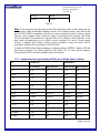
7.11 Messages during OPEN SENSOR condition
Input type
Message
TC-E
OPEN
TC-J
OPEN
TC-K
OPEN
TC-T
OPEN
TC-B
OPEN
TC-R
OPEN
TC-S
OPEN
PT 100
OPEN
0-400Ω
OPEN
0-6000Ω
OPEN
±10V
RANDOM VALUE
0-10V
RANDOM VALUE
0 to 5V DC
UNDER
1 to 5V DC
OPEN
0 to 2V DC
OPEN
0.4 to 2V DC
OPEN
-10 to 20mV DC
OPEN
±75mV
OPEN
0-75mV
OPEN
Serial
-----

Temperature Indicator: 409
REF NO: m59A/om/101
Issue NO: 16
Page 18 of 36
Table 4.
Note: If set zero/span for input type is less then maximum value of zero and span for
then process value will display readings above 5% of display range, then after it will
show OVER/UNDER message until value crosses maximum value of Sensor range.
Process value greater then maximum value of zero/span then display will show
OPEN message. Retransmission o/p will follow 5% of display range and then it will
give fixed o/p depending up on OPEN sensor selection. In case of linear inputs
scaling is applied then during OPEN sensor condition it may not show OPEN
message instead it will show either OVER/UNDER.
If diode is OPEN in that case message on display will be “dOPEN” .Switch OFF the
instrument connects the diode properly and switch ON to have proper display.
During diode OPEN condition modbus gives fixed value.
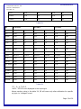
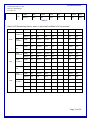
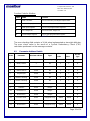
7.12 Retransmission output during OPEN sensor/Diode Open condition
I/P
0-20 mA O/P
4-20 mA O/P
UP Scale O/P
DW Scale O/P
UP Scale O/P
DW Scale O/P
*TC
21.00
0.0
20.8
3.2
Pt-100
21.00
0.0
20.8
3.2
0~5V
21.00
0.0
3.2
3.2
1~5V
21.00
0.0
20.8
3.2
±75mV
21.00
0.0
20.8
3.2
0~75mV
21.00
0.0
20.8
3.2
0~10V
Random
Random
Random
Random
*±10V
Random
Random
Random
Random
0~2V
21.00
0.0
20.8
3.2
0.4~2V
21.00
0.0
20.8
3.2
-10~20mV
21.00
0.0
20.8
3.2
0~6000Ω
21.00
0.0
20.8
3.2
0~400Ω
21.00
0.0
20.8
3.2
4-20mA
OPEN
0-20mA
-19999

Temperature Indicator: 409
REF NO: m59A/om/101
Issue NO: 16
Page 19 of 36
Serial
21.00
0.0
20.8
3.2
4-20mA
21.00
0.0
20.8
3.2
0-20mA
21.00
0.0
3.2
3.2
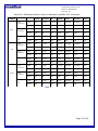
Table 5A.
I/P
0-10 V O/P
0-5 V O/P
1-5 V O/P
UP Scale O/P
DW Scale O/P
UP Scale O/P
DW Scale O/P
UP Scale O/P
DW Scale O/P
*TC
10.50
0.0
5.25
0.0
5.20
0.80
Pt-100
10.50
0.0
5.25
0.0
5.20
0.80
0~5V
10.50
0.0
5.25
0.0
5.20
0.80
1~5V
10.50
0.0
5.25
0.0
5.20
0.80
±75mV
10.50
0.0
5.25
0.0
5.20
0.80
0~75mV
10.50
0.0
5.25
0.0
5.20
0.80
0~10V
Random
Random
Random
Random
Random
Random
*±10V
Random
Random
Random
Random
Random
Random
0~2V
10.50
0.0
5.25
0.0
5.20
0.80
0.4~2V
10.50
0.0
5.25
0.0
5.20
0.80
-10~20mV
10.50
0.0
5.25
0.0
5.20
0.80
0~6000Ω
10.50
0.0
5.25
0.0
5.20
0.80
0~400Ω
10.50
0.0
5.25
0.0
5.20
0.80
Serial
10.50
0.0
5.25
0.0
5.20
0.80
4-20mA
10.50
0.0
5.25
0.0
5.20
0.80
0-20mA
10.50
0.0
5.25
0.0
5.20
0.80
Table 5B.
*TC – E,J,K,T,B,R,S.
*±10V – OPEN is not displayed in this input type.
Above mention value in the table 5A, 5B will come only after calibration for specific
o/p type i.e. Voltage/Current.

Temperature Indicator: 409
REF NO: m59A/om/101
Issue NO: 16
Page 20 of 36
7.13 Relay Delay
Relay delay is the parameter used to set the delay (second) in the operation of
relays (both 1&2).Minimum value of delay is 0(second) and maximum value 9999
(second) can be configured using keyboard.
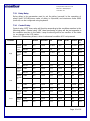
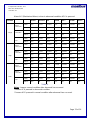
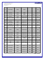
7.14 Control Relay
Control relay “OFF” then relay will function according to the condition mention in the
following tables. Control relay “ON” then functioning of relay will be just opposite to
the condition mention in the table. Lamp functioning will be as mention in the table
i.e. no change in the LED status.
Alarm AL1 (Momentary Alarm): when in abnormal condition ACK not pressed.
Condition
Normal
Abnormal
UP
DOWN
ACK**
Normal*
ACK
***
High
Alarm
Latch(
Yes)
LAMP
OFF
FLASH
FLASH
OFF
FLASH
OFF
RELAY
OFF
ON
ON
OFF
OFF
OFF
Alarm
Latch(
No)
LAMP
OFF
FLASH
FLASH
OFF
OFF
OFF
RELAY
OFF
ON
ON
OFF
OFF
OFF
Trip
LAMP
OFF
FLASH
OFF
OFF
FLASH
OFF
RELAY
OFF
ON
OFF
OFF
ON
OFF
Low
Alarm
Latch(
Yes)
LAMP
OFF
FLASH
OFF
FLASH
FLASH
OFF
RELAY
OFF
ON
OFF
ON
OFF
OFF
Alarm
Ltch(N
o)
LAMP
OFF
FLASH
OFF
FLASH
OFF
OFF
RELAY
OFF
ON
OFF
ON
OFF
OFF
Trip
LAMP
OFF
FLASH
OFF
OFF
FLASH
OFF
RELAY
OFF
ON
OFF
OFF
ON
OFF
VLow
Alarm
Latch(
Yes)
LAMP
OFF
FLASH
OFF
FLASH
FLASH
OFF
RELAY
OFF
ON
OFF
ON
OFF
OFF
Alarm
Latch(
No)
LAMP
OFF
FLASH
OFF
FLASH
OFF
OFF
RELAY
OFF
ON
OFF
ON
OFF
OFF
Page is loading ...
Page is loading ...
Page is loading ...
Page is loading ...
Page is loading ...
Page is loading ...
Page is loading ...
Page is loading ...
Page is loading ...
Page is loading ...
Page is loading ...
Page is loading ...
Page is loading ...
Page is loading ...
Page is loading ...
Page is loading ...
-
 1
1
-
 2
2
-
 3
3
-
 4
4
-
 5
5
-
 6
6
-
 7
7
-
 8
8
-
 9
9
-
 10
10
-
 11
11
-
 12
12
-
 13
13
-
 14
14
-
 15
15
-
 16
16
-
 17
17
-
 18
18
-
 19
19
-
 20
20
-
 21
21
-
 22
22
-
 23
23
-
 24
24
-
 25
25
-
 26
26
-
 27
27
-
 28
28
-
 29
29
-
 30
30
-
 31
31
-
 32
32
-
 33
33
-
 34
34
-
 35
35
-
 36
36


Masibus Process Indicator 409 User manual
- Type
- User manual
Ask a question and I''ll find the answer in the document
Finding information in a document is now easier with AI
Related papers
-
 Masibus 409-4IN User manual
-
 Masibus 409-W Strain Gauge Indicator User manual
-
 Masibus RPM Monitor 409-S User manual
-
 Masibus ON/OFF and Proportional Controller 5002U-P User manual
-
 Masibus Multichannel Vibration Monitor VMS4SE User manual
-
 Masibus Strain Gauge Transmitter SGT-18 User manual
-
 Masibus Dual Channel Vibration Transmitter VT7S12E User manual
-
 Masibus Tap Position Transmitter TPT-20 User manual
-
 Masibus Digital Indicator 406/406L/408-M User guide
-
 Masibus Universal Transmitter UT-94 User manual


Other documents
-
MULTISPAN PIC-1101 Owner's manual
-
Eurotherm Piccolo Controllers User manual
-
-
Chromalox C4-IR Programming Manual
-
-
 West Control Solutions N8080 User manual
-
-
-
-
