Page is loading ...

The PEG-NE24-IP-C is a stand-alone H.264 digital video PEG channel encoder with a single SD/HD-SDI, or
composite video input, and an IP-encapsulation output via a single SFP Ethernet port. A separate RJ45 10/100
Ethernet port is provided for control and monitoring capability.
The PEG-NE24-IP-C features selectable SDI PCM-embedded audio, or analog left and right audio. A Second
Audio Program (SAP) channel is available via a SDI PCM-embedded audio track. Audio compression can be
either Dolby® Digital, MPEG1-Layer 2 stereo, or AAC stereo.
DESCRIPTION
Document#651246900A / Item#1002613A
www.rldrake.com
PEG-NE24-IP-C QUICK GUIDE
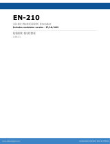
STEP 1: Setup and Login
First, connect the appropriate input and output video cables and plug in the PEG-NE24 power cable.
Local or remote communication with the unit is only possible through a GUI-based menu via any standard
web browser Chrome or Firefox is recommended, for IE use IE8 minimum. Before being able to communicate
with the unit, the user must congure the computer’s Local Area Network connection to be in the same sub-
net as the PEG default IP ( 172.16.70.1 ).
Connect an Ethernet cable from your computer to the Control
10/100 port of the PEG.
• Assign “172.16.70.2” as the static IP address for the control
computer.
• Enter “172.16.70.1” (default address) into the Browser to access
the PEG Encoder.
• Login with Username: “admin” and password “pass”.

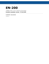
Sets global settings that apply to both streams and the possible outputs.
These settings, for the Primary stream, set parameters for streaming an HD or SD stream, depending on
the video input HD or SD source. See “C: SD Only Stream Settings” for SD-specic settings.
Video Source: Video input selection of SDI or Composite.
Audio Source: Audio input selection of SDI or Analog (L/R).
Audio Synchronization: A/V lip-sync adjustment used to adjust your audio to video synchronization.
Stream Enable: Stream combinations available are:
Video Encoder Format: MPEG-4/H.264
HD Video Bitrate (Mbps): Primary Stream; 3.5 to 13.0 (increments of 0.1) in H.264.
NOTE: Once an input is applied, only the detected resolution will be displayed. Both SD & HD video bitrates are
displayed only when no input is detected.
Video Mode Flag: Setting adjusts video encoder mode for decoder compatibility. The following
options are available:
Frame-Only: Encoding mode used when the video input is progressive (ex. 720p). This mode can also be
used to encode interlaced video (ex. 480i or 1080i).
Field-Only: Encoding mode used when the video input is interlaced (ex. 480i or 1080i). Some decoders may
have compatibility issues when decoding eld encoding.
NOTE: If the video input is 720P the encoding mode will automatically default to Frame-only mode, even if Field-
Only mode is selected in the menu.
Aspect Ratio: As described under “(C) SD-Only Settings”.
1
1
2
2a
3
4
4
5
STEP 2: Configure Encoding
Global Conguration
A
Native Resolution
B
1
3
2
4
Disable: Encoder is not streaming.
Native: Encoder will stream an HD or SD
stream depending on the video input being
HD or SD source.
SD Only: Encoder streams a SD stream regardless of
video input being HD or SD source.
Native + SD: Encoder streams an HD and SD stream
or a SD stream and SD stream depending on video
input being HD or SD source.
VIDEO SETTINGS

This section is for the SD-only stream and sets parameters for
streaming SD off the video input source. Most of the settings
are the same as those found under Native Resolution, with
the following exceptions:
Audio Encoder Format: Select MP2 for MPEG-1
Audio Layer 2; AC-3 for Dolby Digital AC-3; AAC
(Advanced Audio Coding).
Audio DialNorm (dB): -1 to -31 (increments of 1).
Provides meta-data for audio playback gain for
Dolby AC-3 compression.
Audio Bitrate: 128, 192 or 384 Kbps.
HD TS Bitrate (Mbps): Primary Stream; 0.415 to 25
incremented by 0.125 (TS bitrate must be greater
than 0.400 Mbps + audio bitrate + video bitrate).
Destination IP / Destination Port: User-dened
unicast or muliticast IP address and port number
determined by downstream network connectivity
device.
IP Stream TTL: 1 to 255, determined by application.
6
7
2b
8
9a
5
11
12
STEP 2: Configure Encoding (continued)
SD Only Stream Settings
C
AUDIO SETTINGS
TRANSPORT STREAM SETTINGS
IP SETTINGS
SD Video Bitrate (Mbps): 1 to 4 (increments of 0.1)
in H.264. SD Only must be enabled to use under
Native Resolution.
Aspect Ratio: Aects only SD 480i inputs. Video
display can be set for 4:3 (normal SD) or 16:9
(widescreen). SD Only must be enabled to use
under Native Resolution. When native resolution is
720p or 1080i, the SD only output can be set as the
following:
SD TS Bitrate (Mbps): 2 to 25 incremented by
.125. SD Only must be enabled to use under
Native Resolution.
9b
5
2b
1
3
7
8
2
6
4
9a
12
11
16:9 4:3 Squeeze - 640 x 480
4:3 4:3 Letterbox - 640 x 480
4:3 Letterbox - 720 x 480 4:3 Center - 640 x 480
4:3 Center - 720 x 480
9b

Download the full manual for more information on congurable options and settings at:
www.rldrake.com
CONTACT DRAKE FOR MORE INFO | TECH SERVICES: 937-746-6990
STEP 3: System Configuration: Network
The system conguration tab allows the user to set
Ethernet and SNMP settings.
Network Conguration Mode:
• Advanced Mode: enables the SFP output port and
associated settings.
• Simple Mode: allows streaming out the front-panel control
port and disables the SFP port.
SFP Video Network Settings:
• Mac Address: read-only.
• DHCP Enable: Enables or Disables DHCP.
• IP address: the static IP address. (Default: 172.16.80.1)
• Subnet Mask: the subnet mask address.
• Default Gateway: the Gateway Address.
• HTTP Server Enable: “Enabled”: allows management
capability on the same SFP port (SFP port IP Address) as the
streaming video.
• Link Speed (copper only): Default setting is Auto.
• VLAN Enable: Enables or Disable VLAN.
• VLAN Tag: allows user to set dened VLAN Tag for the unit.
SFP Control-Only VLAN Settings: Enables or disable VLAN
Settings for Control-Only.
Control Port Ethernet Settings:
• MAC Address: read-only; “Control 100/1000” Port.
• IP Address: the static IP address assigned to unit allows user
access via web interface.
• Subnet Mask: subnet mask address of unit allows user to
access from another network via web interface.
• Default Gateway: gateway address of unit allows user to
access from another network via the web interface.
DNS Settings:
• DNS Mode: Options are DHCP Provided or Manual mode.
When in manual mode, enter Primary, Secondary name
servers and/or Search Domains in the space provided.
• Name Servers: read-only; indicates conversion from domain
names to IP addresses.
• Setting the UTC Time: (See manual for more methods)
1. Set DHCP enable on SFP Video
2. Enable HTTP Server
3. Set DNS settings to DHCP Provided
Unit Description: Unit Name / User Location are user-dened
for easier identication.
SNMP Settings: Simple Network Management
Protocol (SNMP) monitoring for the unit. Settings
include: Trap Target IP, Trap Target Port, and System
Contact.
Web Settings: User Timeout - Range is 5 to 30
minutes (increments of 5)
1
2
3
4
5
6
8
7
1
3
2
4
5
6
7
8
/