Radiant Communications VL4510 User manual
- Type
- User manual

VL4500 ENCODER SERIES
Installation and Operations Manual
User Guide
Radiant
Communications
Corporation

V L 4 5 0 0 E N C O D E R S E R I E S
Installation and Operation Manual
Radiant Communications Corp. 2016
5001 Hadley Road
South Plainfield, NJ 07080
Phone 908.757.7444 • Fax 908.757.8666
www.rccfiber.com

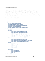
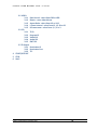
Table of Contents
Product Summary .................................................................... 1
Application ...................................................................................... 1
Features .......................................................................................... 2
Front Panel ..................................................................................... 3
Rear Panel ...................................................................................... 4
Encoding Profiles ............................................................................ 6
Output Interfaces ............................................................................ 6
Energy Specifications...................................................................... 6
Installation ................................................................................ 7
Communication ........................................................................ 8
Network Management ..................................................................... 8
Configuration ............................................................................ 9
Video Settings ............................................................................... 10
Audio Settings ............................................................................... 15
TS Settings ................................................................................... 17
Network Settings ........................................................................... 20
System Setup ................................................................................ 22
Firmware Upgrade: ................................................................................. 25
User Presets ................................................................................. 26
Encoder Default Settings .............................................................. 27
Front Panel Interface..................................................................... 28
Revisions ............................................................................... 30

V L 4 5 0 0 U S E R M A N U A L R E V . 2 . 2 . 0 60
Radiant Communications Corporation 2016 1
Product Summary
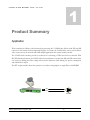
Application
With compression efficiency and advanced pre-processing the VL4500 Series delivers both HD and SD
content at a low bitrates and uncompromised quality. As a result, the VL4500 Series can be used to deliver
video services across all networks and fulfill multiple applications for various business models.
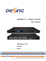
The VL4500 Series encoders provide cost-effective live streaming of PEG and in-house channels. With
SD/HD simulcast function, the VL4500 allows the broadcaster to stream both SD and HD content from
one source by utilizing the video scaling and conversion functions while utilizing low power consumption
and minimal heat output.
The SFP output interface allows the operator to use either existing duplex or single fiber or 1000B RJ45.
PEG STUDIO
VL4500
text
CATV HUB
SFP
FIBER
DOCSIS
1

V L 4 5 0 0 U S E R M A N U A L R E V . 2 . 2 . 0 60
Radiant Communications Corporation 2016 2
Features
• Multi-Stream Encoding
• Superior HD Quality at Low Bitrates
• Out-of-Band Management
• Advanced Video Pre-Processing
• GigE TS Interface
• MPEG2 SD/HD
• H.264 AVC SD/HD
• VBR and CBR Encoding
• AC-3 Audio Encoding
• EIA-708 Closed Caption Support
• IP, ASI and QAM output Options
• Video Scaling and Conversion
• Low Power Consumption and Heat Dissipation

V L 4 5 0 0 U S E R M A N U A L R E V . 2 . 2 . 0 60
Radiant Communications Corporation 2016 3
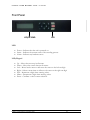
Front Panel
LCD/KEYPAD LED
LED
Power – Indicates that the unit is powered on.
Status – Indicates the current status of the encoding process.
Alarm – Indicates any hardware errors
LCD/Keypad
Up – Moves the cursor up in all menus.
Down – Moves the cursor down in all menus.
Left – Moves back a menu or will move the cursor to the left one digit.
Right – Selects a menu item or will move the cursor to the right one digit
Plus – Increments a digit when entering values.
Minus – Decrements a digit when entering values.
Enter – Confirms a value or menu selection.

V L 4 5 0 0 U S E R M A N U A L R E V . 2 . 2 . 0 60
Radiant Communications Corporation 2016 4
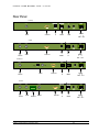
Rear Panel
POWER
+ V
TS OUT
EARTH
TS
SDI IN
TS OUT
SDI IN
RS232
Serial Port
MGMT
MGMT
10/100/1000
VL4510Q
10/100/1000
QAM
QAM
POWER
1 2
GND +12 V
POWER
+ V
EARTH
TS
SDI IN
TS OUT
SDI IN
RS232
Serial Port
MGMT
VL4510
ASI OUT
ASI OUT
10/100/1000
SFP
MGMT
TS OUTPUT
POWER
1 2
GND +12 V
POWER
+ V
10/100/1000
EARTH
TS
SDI IN
SDI IN
RS232
Serial Port
SFP
MGMT
MGMT
VL4500/SDI
TS OUTPUT
ASI OUT
ASI OUT
LOCK
RX|TX
LINK
POWER
1 2
GND +12 V
POWER
+ V
TS OUT
EARTH
TS
SDI IN
TS OUT
SDI IN
RS232
Serial Port
MGMT
MGMT
10/ 100/ 1000
VL4510C
10/ 100/ 1000
ASI OUT
ASI OUT
CVBS IN
CVBS IN
1 2 3 4 5
AUDIO IN
POWER
1 2
GND +12 V

V L 4 5 0 0 U S E R M A N U A L R E V . 2 . 2 . 0 60
Radiant Communications Corporation 2016 5
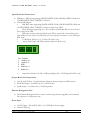
Input Rear Panel Connections:
SDI Input – SDI input supporting SD-SDI (SMPTE-259M), HD-SDI (SMPTE-292M) and
3G-SDI (SMPTE-424M), 75Ω BNC Connector
VL4500/SDI Inputs:
o SDI BNC input supporting SD-SDI (SMPTE-259M), HD-SDI (SMPTE-292M) and
3G-SDI (SMPTE-424M), 75Ω BNC Connector, Signal Lock LED
o Fiber SDI input supporting up to 3G over fiber. SFP Module RX port is on the left
side, Optical Link LED
o SDI input switches with optical link status. When optical link is detected the active
input SDI port is the optical. If optical link is lost the input port switches to coax SDI input
BNC port.
o CVBS Input, NTSC 1Vp-p, 75 Ohm.(VL4510C only)
o Analog Audio Input, 600 Ohm, balanced Input(VL4510C only)
1 2 3 4 5
Pin Function
1 Audio In 1 +
2 Audio In 1 -
3 GND
4 Audio In 2 +
5 Audio In 2 -
o Input Select Switch. Left Side – SDI Input; Right Side – CVBS Input(VL4510C only)
Output Rear Panel Connections:
10/100/1000 TS Port – Gigabit Ethernet Transport Stream Output via SFP Interface
DVB ASI Output – Available only on VL4510 models.
QAM Output – Available only on VL4510Q model
Ethernet Management Port
The Ethernet Management Port is used for monitoring, firmware upgrades, and command
line interface to configure the unit.
Power Input
12V DC Input – Pin1(GND), Pin2(+V), 12VDC@4A Power Supply
Chassis GND Lug

V L 4 5 0 0 U S E R M A N U A L R E V . 2 . 2 . 0 60
Radiant Communications Corporation 2016 6
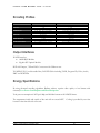
Encoding Profiles
MPEG2
h.264
PROFILE
MPEG-2 MP@HL ISO/IEC 13818-2
AVC H.264 high profile levels 4.1 and 4.2
CHROMA
4:2:0
4:2:0
RESOLUTION
480i, 480p, 720p, 1080i and 1080p
480i, 480p, 720p, 1080i and 1080p
FRAME RATE
24, 25, 29.97, 30, 59.94 and 60fps
24, 25, 29.97, 30, 59.94 and 60fps
ASPECT RATIO
4:3 and 16:9
4:3 and 16:9
PICTURE TYPE
IP, IPB, IPBB
IP, IPB, IPBB, IPBBB
GOP SIZE
10-60 frames
10-60 frames
GOP STRUCTURE
IBB or BBI
IBB or BBI
VIDEO BITRATE
1.5-24M
500k-24M
VIDEO SCALING
DOWN Conversion
DOWN Conversion
AUDIO ENCODING
AC3 2.0, MPEG Layer II. and AAC
AC3 2.0, MPEG Layer II. and AAC
AUDIO SAMPLING RATE
48kHz
48kHz
AUDIO BIT RATE
96-384kHz
96-384kHz
Output Interfaces
IP: SFP Interface
1000B RJ45 Module
Gigabit SFP Optical Module
DVB ASI Output, 75Ohm BNC Connector with 54M max rate
TS: MPEG2 TS, User Selectable Rate, Full PID Table including TS ID, Program ID, Video, Audio,
PMT and PCR PIDs
Energy Specifications
By using advanced encoding algorithms Radiant achieves superior video quality at low bitrates with
extremely Low Power Consumption and Heat Dissipation.
Total power consumption is 24W per 1080p and 480i dual stream at full 19M TS bitrate.
The temperature inside and outside of the unit will not exceed 40⁰C. Cooling is provided by two fans
located on the front left side of the unit.

V L 4 5 0 0 U S E R M A N U A L R E V . 2 . 2 . 0 60
Radiant Communications Corporation 2016 7
Installation
The VL4500 chassis can be mounted in a standard EIA, 19” rack.
Secure the Encoder’s front panel to the rack by inserting four machine screws, with cup washers,
through the four mounting holes in the front panel.
When installing one or more encoders in a headend rack, it is recommended to leave a 1 rack unit
space (1.75” high) between units to maximize air flow.
To power up the unit, connect the 12VDC power supply to the unit.
If both power sources are connected they will act as redundant power supplies.
The POWER LED on the front-panel will light green and the LCD screen will turn on.
The standard boot-up time is less than one minute, after successful boot-up the LCD screen will read
“VL4500”
2

V L 4 5 0 0 U S E R M A N U A L R E V . 2 . 2 . 0 60
Radiant Communications Corporation 2016 8
Communication
The Encoder can be controlled and managed with either the out-of-band network port located on
the front panel or via the RS232 serial port. In-band management through the TS port is possible as
well.
Network Management
Initially, the simplest way to setup the networked PC to communicate with the VL4500 is to put the PC on
the same subnet as the VL4500. The default IP address of the VL4500 management port is:
192.168.16.252
NOTE: The static IP of the computer cannot be the same as the static IP of the VL4500.
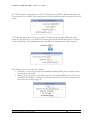
The following steps explain how to change the IP address of a computer running windows 7:
1. On your computer, open the "Control Panel"
2. Click on “Network and Internet”
3. Click on the "View network status and tasks"
4. Click on “Change Adapter Settings” on left hand side of the window
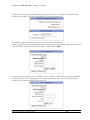
5. Right-click on the "Local Area Connection", and then click on the "properties".
6. A dialog box entitled "Local Area Connection Properties" will appear. In this box, double-
click on the "Internet Protocol Version 4 (TCP/IPv4)".
7. A dialog box entitled "Internet Protocol Version 4 (TCP/IPv4) Properties" will appear.
8. Select the "Use the following IP address" option and enter the following addresses:
IP address: 192.168.16.2
Subnet mask: 255.255.255.0
9. Click OK to close the dialog box. Now your computer is ready to communicate with the unit.
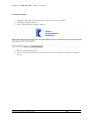
10. Open an Internet Explorer web browser on your computer and enter the following URL
http://192.168.16.252
3

V L 4 5 0 0 U S E R M A N U A L R E V . 2 . 2 . 0 60
Radiant Communications Corporation 2016 9
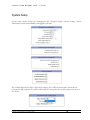
Configuration
The VL4500 Web management system is accessible through both TS and MGMT Ethernet interfaces.
Settings are grouped by tabs for:
Video Settings
Audio Settings
TS Settings
Network Settings
System Settings
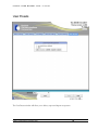
User Presets
Note:
Changed settings will take effect only after the Encoder is started or restarted via the buttons on the
bottom of the screen.
Settings can be saved to a desired preset; preset includes also the current state of the Encoder
The encoder is being shipped with encoder factory preset. Saving on that preset is not possible. After the
unit is configured, a new preset should be created and saved.
4

V L 4 5 0 0 U S E R M A N U A L R E V . 2 . 2 . 0 60
Radiant Communications Corporation 2016 10
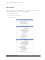
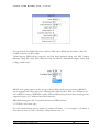
Video Settings
Under Video Settings tab, the user can set specific codec parameters and SDI Video Input signal
information, that includes Input resolution and frame rate. Supported are:
1080i at 24, 29.97 and 30 fps
720p at 29.97, 30, 50, 59.94 and 60 fps
480i at 29.97 and 30 fps

V L 4 5 0 0 U S E R M A N U A L R E V . 2 . 2 . 0 60
Radiant Communications Corporation 2016 11
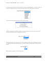
The output resolution follows the input resolution of the incoming SDI signal or it could be forced. In
case that the output resolution is forced the input signal must have the same resolution as the input.
The detected resolution and frame rate are shown on the web page.
VL4510C unit supports either SDI or composite video input. Selection of the active video input can be
done from the dropdown menu of Input Source parameter.
Encoding field order can be selected to either TFF (top field first) or BFF (bottom field first). When down
converting from HD to SD with QBA support for old legacy STB, set the filed order to TFF for the SD
encoder.
H264 encoding is supported only in BFF field order.

V L 4 5 0 0 U S E R M A N U A L R E V . 2 . 2 . 0 60
Radiant Communications Corporation 2016 12
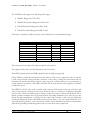
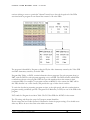
The VL4500 encoder supports the following bitrate ranges:
MPEG2 Range from 7M to 25M
MPEG2 SD resolution Range from 1M to 15M
H264 HD resolution Range from 2M to 25M
H264 SD resolution Range from 500k to 25M
The bitrate is adjustable in 100K increments, see the table below for recommended settings:
Output Stream(s)
Video 1 (HD/SD), kbps
Audio, kbps
Output Bitrate, kbps
MPEG2, 1080p SPTS
16000
192
19600
h.264, 1080p SPTS
12000
192
13500
MPEG2, 1080i SPTS
12000
192
15000
h.264, 1080i SPTS
8000
192
9500
MPEG2, 720p SPTS
9000
192
12000
h.264, 720p SPTS
6000
192
7500
MPEG2, 480i(p) SPTS
3500
192
5000
h.264, 480i(p) SPTS
1500
192
2000
The user can select the aspect ratio and rate control for the encoder.
The supported video ratios are 16:9 (widescreen) and 4:3 (normal).
Both CBR (constant bit rate) and VBR (variable bit rate) encoding are supported
Under VBR rate control the encoder will vary the amount of bits used to represent a frame so that the
overall average amount of bits-per-frame is achieved. It does this by taking bits from frames with less
information to encode (that don't need them) and giving them to frames that have more information to
encode (and does need them). With CBR each frame uses the same amount of bits regardless of whether
it needs them or not.
The MPEG2 or h.264 video needs a suitable GOP structure. GOP stands for 'Group of Pictures' and
refers to the sequence of frames in the stream. When the video is encoded, the compression algorithm
puts the video content into different types of frame, usually just I-frames, P-frames and B-frames. The I-
frames are almost complete and can be played without any further information, they don't rely on other
frames for their interpretation or playing. On the other hand, P-frames contain only the details that
describe the differences between that frame and the previous frame – they are forward 'Predicted'. A B-
frame ('Bi-predictive picture'), on the other hand, contains only the differences between the current frame
and both the preceding and following frames and, as a result, allows more compression.

V L 4 5 0 0 U S E R M A N U A L R E V . 2 . 2 . 0 60
Radiant Communications Corporation 2016 13
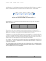
A GOP consists of an initial I-frame and a sequence of P and B frames. The GOP length is the number of
frames in each repeated sequence (one I-frame in each) and it’s being set via the I-Frame interval.
A typical GOP with structure ’IBBP’, and I-Frame interval of 15
Standard practice is to use GOP with an I-Frame interval that’s half of the input video frame rate for
MPEG2, and full for h.264
Video frame rate
MPEG2 I-Frame Interval
h.264 I-Frame Interval
24fps
12
24
29.97, 30fps
15
30
59.94, 60fps
30
60
B-frames improve the quality of the picture, but they also increase the latency by 1 frame time. To
minimize latency, B-frames should be lowered or disabled. Recommended encoding GOP for MPEG2 is
IBBP, which has 2 B frames, and for MPEG4/h.264 is IBBBP, which has 3 B frames.
A problem that occurs while using MPEG compression is error propagation. It is obvious that when there
is an error in the I-frame and following frames are calculated with this frame, the error will continue in
these frames as well. This is one of the reasons the GOP structure is repeated. It ensures a new I-frame to
rebuild a perfect image, although the arrival of the I-frame might take some time.
For fast motion video that needs to be encoded at lower bitrate it is recommended that the GOP size be
set to 12 or lower. For slow to moderate motion or digital signage video the GOP size should set to half
of incoming vide frame rate.
The VL4500 Encoder provides a dual stream output, one in HD resolution and a second down-converted
to SD resolution. If 1xHD+1xSD mode is selected in the Settings tab (see page xx) the bitrate resolution
and GOP structure needs to be set as shown below.

V L 4 5 0 0 U S E R M A N U A L R E V . 2 . 2 . 0 60
Radiant Communications Corporation 2016 14
The typical bitrate for MPEG2 SD service is 3000 to 3500k and for MPEG4/h.264 1000 to 1500k. The
available resolutions are 480i or 480p.
Vl4500 supports MPEG4/h.264 progressive and field based interlaced coding with ARF (Adaptive
Reference Field), SPF (Same Parity Reference Field) and MBAFF (Macroblock-Adaptive Frame/Field
Coding) control modes.
MBAFF mode greatly improves quality for a given bitrate. Being a relatively new technology MBAFF is
still not supported well among legacy AVC hardware and software decoders. While not as efficient as the
newer MBAFF, in terms of bandwidth vs quality, SPF and ARF modes perform in faster encoding and are
supported by legacy AVC hardware and software decoders.
HRD buffer Setting for h.264. To manually calculate max HRD Buffer use:
(17178750*8)/video bitrate (bps)
For h.264 I-frame Interval must be multiple of (number of B frames + 1). For example, 2 x B-frames, I-
frame interval can be 30. With 3 x B-frames, I-frame interval can be 32.

V L 4 5 0 0 U S E R M A N U A L R E V . 2 . 2 . 0 60
Radiant Communications Corporation 2016 15
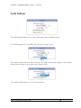
Audio Settings
The Audio Settings tab allows you to set the audio codec, bitrate and channel mode.
The VL4500 supports AC3 2.0, MPEG Layer II and AAC audio codecs.
The channel mode can be set to Mono or Stereo. The Mono mode actually supports a dual channel,
allowing the encoding of two separate audio channels (SAP).
.
The available audio bitrates are 96, 128, 192 and 384k.

V L 4 5 0 0 U S E R M A N U A L R E V . 2 . 2 . 0 60
Radiant Communications Corporation 2016 16
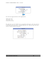
Note: The only supported mode for CATV applications is:
Audio Codec: AC3
Audio Bitrate: 192k
Channel: Mono/Stereo
The audio input source for VL4510C units is automatically switch based on video input selection.
For SDI input, audio input defaults to embedded SDI audio. For CVBS video input audio input
defaults to 600Ohm balanced analog audio.

V L 4 5 0 0 U S E R M A N U A L R E V . 2 . 2 . 0 60
Radiant Communications Corporation 2016 17
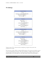
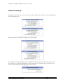
TS Settings
Transport stream (TS) is a format that allows multiplexing of digital video and audio and
synchronizes the output.
The TS consists of single (SPTS) or multiple (MPTS) programs. The programs are defined by groups
of one or more PIDs that are related to each other. For instance, a transport stream used in digital
television might contain three programs, to represent three television channels. Suppose each
channel consists of one video stream, one or two audio streams, and any necessary metadata. A
Page is loading ...
Page is loading ...
Page is loading ...
Page is loading ...
Page is loading ...
Page is loading ...
Page is loading ...
Page is loading ...
Page is loading ...
Page is loading ...
Page is loading ...
Page is loading ...
Page is loading ...
Page is loading ...
-
 1
1
-
 2
2
-
 3
3
-
 4
4
-
 5
5
-
 6
6
-
 7
7
-
 8
8
-
 9
9
-
 10
10
-
 11
11
-
 12
12
-
 13
13
-
 14
14
-
 15
15
-
 16
16
-
 17
17
-
 18
18
-
 19
19
-
 20
20
-
 21
21
-
 22
22
-
 23
23
-
 24
24
-
 25
25
-
 26
26
-
 27
27
-
 28
28
-
 29
29
-
 30
30
-
 31
31
-
 32
32
-
 33
33
-
 34
34


Radiant Communications VL4510 User manual
- Type
- User manual
Ask a question and I''ll find the answer in the document
Finding information in a document is now easier with AI
Related papers
-
Radiant Communications VL4500 SRT Encoder User manual
-
-
-
-
-
-
Radiant Communications VAB700SD User manual
-
-
-
Other documents
-
 Dexin NDS3208 User manual
-
Clinton Electronics CE-EX-VDA16 User manual
-
-
Terra mhi430 Owner's manual
-
Televes Modulator Encoder Quick start guide
-
-
-
DRAKE PEG-NE24-IP-C Quick Manual
-
 Adtec Digital EN-30 Quick start guide
-
 TANDBERG EN5990/BAS/48V User manual


